1
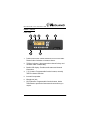
User’s Guide Olympian™ Series MO-1008 Eight Channel VHF-FM Mobile Transceiver MO-4008 Eight Channel UHF-FM Mobile Transceiver MO-1016 Sixteen Channel VHF-FM Mobile Transceiver MO-4016 Sixteen Channel UHF-FM Mobile Transceiver MO-1008 / 4008 / 1016 / 4016 User’s Guide November 2004 2 © 2004, Midland Radio Corporation MO-1008 / 4008 / 1016 / 4016 User’s Guide FCC RF EXPOSURE COMPLIANCE REQUIREMENTS FOR OCCUPATIONAL USE ONLY The FCC has adopted a safety standard for human exposure to RF energy. Proper operation of this radio under normal conditions results in user exposure to RF energy below the Occupational Safety and Health Act and Federal Communication Commission limits. Mandatory Safety Instructions to Installers and Users: This radio is NOT approved for use by the general population in an uncontrolled environment. This radio is restricted to occupational use and work related operations only. Radio operators must have the knowledge to control their exposure conditions and the exposure conditions of bystanders and/or passengers to satisfy the lower exposure limit allowed for General Population. To comply with FCC RF exposure limits, DO NOT operate the transmitter of this mobile radio when a person outside the vehicle is within 36 inches (92 centimeters) of the antenna. The antenna supplied by the manufacturer or radio dealer must be mounted at a location such that during radio transmission, no person or persons can come closer than the above indicated minimum safe distance to the antenna, i.e. 36 inches. To comply with current FCC RF exposure limits, the antenna must be installed at or exceeding the minimum safe distance stated above, and in accordance with the requirements of the antenna manufacturer or supplier. Vehicle Installation Instructions: The antenna used for this transmitter must be mounted on the center of the roof ONLY and must be installed in vehicle having the following characteristics in order to prevent bystanders and passengers from being exposed to levels exceeding the limits for General Population/Uncontrolled Exposure environment: 1. All passengers must be sitting under a solid metal roof. 2. Rooftop width must be at least 72 inches (183 centimeters) OR the edges of the physical boundary of the vehicle must be at least 72 inches apart. DO NOT operate the radio without the proper antenna installed. Do not substitute any antenna for the one supplied or recommended by the manufacturer or radio dealer. The antenna gain must not exceed 0 dBd. By not following the antenna recommendations you may be exposing person(s) to excess radio frequency radiation. You may contact your radio dealer or the manufacturer for further instructions. DO NOT transmit more than 50% of total radio use time (50% duty cycle). Transmitting for more than 50% of the time can cause FCC RF exposure compliance requirements to be exceeded. This radio is transmitting whenever the TX/Busy indicator is red or the 7 icon is displayed. Pressing the PTT switch on the side of the microphone normally causes the radio to transmit. The preceding information is provided to make you aware of RF exposure and how to ensure that this radio is operated within FCC RF exposure limits. You, as the qualified end-user of this radio device must control the exposure conditions of bystanders to ensure the minimum separation distance, stated above for satisfying FCC RF exposure compliance, is maintained between the antenna and nearby persons. Transmit only when all person(s) are at least the minimum distance from the © 2004, Midland Radio Corporation 3 MO-1008 / 4008 / 1016 / 4016 User’s Guide Contents Conventions and Symbols in this Book ................................... 5 Disclaimer ................................................................................ 4 Safety ....................................................................................... 4 Introduction .............................................................................. 6 Radio Features..................................................................... 7 Radio Controls ......................................................................... 9 Front Panel........................................................................... 9 Rear Panel ......................................................................... 10 Backlit LCD Details............................................................. 10 Setup...................................................................................... 11 Unpacking .......................................................................... 11 Installation .......................................................................... 11 Basic Operation ..................................................................... 12 Turning the Radio On and Off ............................................ 12 Channel Selection .............................................................. 12 Receiving Transmissions from Other Radios..................... 12 Transmitting to Other Radios ............................................. 14 Scanning Channels ............................................................ 15 Programmable Functions....................................................... 18 Message Display Quick Reference........................................ 20 Specifications......................................................................... 23 MO-Series Connectors .......................................................... 24 Warranty Statement ............................................................... 25 4 © 2004, Midland Radio Corporation MO-1008 / 4008 / 1016 / 4016 User’s Guide Conventions and Symbols in this Book 7 This symbol marks a “caution”. Cautions are special notices which you should read and follow carefully to avoid possible damage to your equipment and to avoid potential danger to yourself or other people. ! This symbol marks an “important point”. Important points are specific instructions which should be followed closely for proper operation. This symbol marks a “note”. Notes are hints or tips which offer additional information to help you. Disclaimer Midland Radio Corporation is committed to continuous quality improvements, for this reason specifications may change without prior notice. Every effort has been made to ensure that the information in this document is complete, accurate, and up-to-date. Midland assumes no responsibility for the results of errors beyond its control. The manufacturer of this equipment also cannot guarantee that changes in the equipment made by unauthorized people will not affect the transceiver’s performance or functions. Safety Your MO-1008 / 4008 / 1016 / 4016 mobile transceiver has been carefully designed to give you years of safe, reliable performance. As with all electrical equipment, however, there are a few basic precautions you should take to avoid injury to yourself or damage to the radio: 7 Read the instructions in this book carefully. Be sure to save it for future reference. 7 Read and follow all warning and instruction labels on the radio itself. © 2004, Midland Radio Corporation 5 MO-1008 / 4008 / 1016 / 4016 User’s Guide 7 Be sure the PTT button is not pressed when you do not need to transmit. 7 Do not operate the radio near unshielded electrical blasting caps or in an explosive atmosphere. 7 Do not operate the transmitter of any radio unless all RF connectors are secure. 7 All equipment must be properly grounded for safe operation. 7 Do not allow children to operate or play with the radio equipment. 7 Never attempt to disassemble or service the radio yourself. All equipment should be serviced by a qualified technician. Contact you local dealer or communications coordinator for assistance. 7 It is mandatory that radio installations in vehicles fueled by liquefied petroleum gas conform to the NFPA 58 standard. National Fire Protection Association Standard, NFPA 58, applies to radio installations in vehicles fueled by liquefied petroleum (LP) gas with the LP gas container in the trunk or other sealed-off space within the interior of the vehicle. This standard requires that: 1. Any space containing radio equipment shall be isolated by a seal from the space in which the LP gas container and its fittings are located. 2. Remote (outside) filling connections shall be vented to the outside. 7 Do not allow the antenna to touch or come in very close proximity with the eyes, face, or any exposed body parts while the radio is transmitting. The above warning list is not intended to include all hazards that may be encountered when using this radio. 6 © 2004, Midland Radio Corporation MO-1008 / 4008 / 1016 / 4016 User’s Guide Introduction Congratulations! By choosing the Midland Olympian™ Series MO-1008 / MO-4008 / MO-1016 / MO-4016 mobile transceiver, you have selected a professional grade radio. Its rugged design will provide years of reliable service and its sophisticated software allows many customizable options. Radio Features Your Olympian Series mobile transceiver is a fully programmable, synthesized radio featuring: 5 8 or 16 channel capacity. 5 45 Watts (UHF)/50 Watts (VHF) transmit power. 5 Watt low power selection available. 5 12.5 KHz and 25 KHz channel spacing programmable per channel. 5 6 fully programmable buttons. The function of each button is assigned by dealer programming. 5 Noise squelch level software programmable per channel. The channel squelch level may also be adjusted using a programmable button. 5 Flexible scan programming allows for two priority channels to be assigned. Priority scan, priority transmit and priority lookback are programmable. Scan talkback and nuisance delete are available. 5 50 CTCSS tones and 104 DCS codes are programmable per channel. In addition, up to three custom CTCSS tone frequencies may be programmed into the radio. 5 A 2-tone decode sequence may be programmed for each channel. Up to 10 sequences are programmable per radio. Each sequence includes setup for individual and group calls. © 2004, Midland Radio Corporation 7 MO-1008 / 4008 / 1016 / 4016 User’s Guide 5 A 2-tone call function may be programmed for each channel. One of the 10 available 2-tone sequences may be sent with a programmable button press. 5 A busy channel lockout feature is programmable per channel. An override function is available to allow transmission during repeater hangtime. 5 A transmit time-out timer may be programmed to limit continuous transmission time. A PTT release and penalty timer are also programmable. 5 A public address mode allows the radio and microphone to be used as a public address system when connected to an external public address speaker. 5 A talk-around function button may be programmed to allow for repeater talk-around without using an additional channel. 5 A programmable emergency mode may be activated by a programmable function button or external foot-switch. 5 An external horn output is available to notify you of a call when you’re away from the vehicle. 5 A password function is available to prevent unauthorized radio operation. When programmed, a four keypress sequence must be entered each time the radio is turned on, in order to operate the radio. 8 © 2004, Midland Radio Corporation MO-1008 / 4008 / 1016 / 4016 User’s Guide Radio Controls Front Panel 1 2 6 3 4 5 7 1. Power/volume knob. Rotate clockwise to turn on the radio. Rotate further clockwise to increase volume. 2. TX/Busy indicator. Lights green when channel is busy and red when radio is transmitting. 3. Backlit LCD display. Provides radio status and channel information. 4. [∼]/[ ] buttons. Programmable function buttons, normally used for channel selection. 5. Internal front speaker. 6. Microphone jack. 7. [A]-[D] buttons. Programmable function buttons, dealer customized to provide the features and convenience you require. © 2004, Midland Radio Corporation 9 MO-1008 / 4008 / 1016 / 4016 User’s Guide Rear Panel 1 2 3 4 1. SO-239 antenna connector. 2. 13.6 V DC power connector (negative ground only). 3. 3.5 mm mono audio jack for external speaker connection. 4. High density DB15 option interface connector. Backlit LCD Details 10 © 2004, Midland Radio Corporation MO-1008 / 4008 / 1016 / 4016 User’s Guide Setup Unpacking The following items are supplied in the standard package: 5 One transceiver (MO-1008, MO-4008, MO-1016 or MO4016). 5 One microphone. 5 One mounting bracket. 5 One mounting hardware package. 5 One user’s manual. Installation Radio installation should only be done by qualified and trained personnel, familiar with automotive electronics installation, and FCC RF exposure guidelines. This transceiver should be installed in 12V negative ground vehicles only. More complete installation instructions are available in the corresponding radio service manual. Antenna selection, installation and positioning requires knowledge of RF radiation and exposure conditions and should be performed by qualified personnel only. Please consult your dealer or communications coordinator for more information. © 2004, Midland Radio Corporation 11 MO-1008 / 4008 / 1016 / 4016 User’s Guide Basic Operation ! Before turning on your radio for the first time, you should ensure power connections have been made correctly and all antenna connections are proper and secure. Turning the Radio On and Off Rotate the power/volume knob clockwise past the detent to turn on the radio. Rotate the power/volume knob further clockwise to increase the volume. Rotate the power/volume knob counterclockwise past the detent to turn off the radio. If “PP” is displayed after turning on the radio, you must enter the programmed password (4 keypress sequence) to use the radio. Consult your dealer or communications coordinator if you have further questions. Channel Selection Use the up and down keys to select the desired operating channel. Please consult your dealer or communications coordinator regarding channels programmed in your radio. Press and hold the up and down keys to quickly scroll through the available channels. Receiving Transmissions from Other Radios Each channel of your radio may be programmed for carrier squelch operation, CTCSS/DCS operation or 2-tone operation. The following paragraphs describe these modes of operation. Ask your dealer or communications coordinator if you have questions on how your radio has been programmed to operate. Carrier Squelch Operation A signal that matches the programmed receive frequency will be heard if it is of sufficient strength to exceed the squelch threshold. An on frequency signal exceeding the squelch 12 © 2004, Midland Radio Corporation MO-1008 / 4008 / 1016 / 4016 User’s Guide threshold level will be indicated by a steady green Tx/Busy indicator. CTCSS/DCS Operation CTCSS or DCS signaling adds an additional condition to carrier squelch operation. In addition to the signal having to exceed the squelch threshold level, the received signal must also have the correct CTCSS or DCS tone or code before the audio will be passed to the speaker. CTCSS or DCS signaling allows multiple users on the same frequency to hear only signals which have their correct CTCSS tone or DCS code. An on frequency signal with the correct CTCSS or DCS signaling will be indicated by a steady green Tx/Busy indicator. An amber Tx/Busy indicator means that the channel is busy, but the correct CTCSS or DCS signaling is not present. CTCSS/DCS allows multiple users to share the same frequency. However CTCSS/DCS is only useful to avoid disturbing other users with messages not related to them. If more than one radio is transmitting at the same time, this will cause interference. Do not transmit if the Tx/Busy indicator is illuminated green or amber. Wait until the channel is clear before transmitting. 2-tone Operation 2-tone signaling allows individual or group calls to be made to your radio. The radio may have been programmed to mute all receive signals until a 2-tone signal has been decoded. When the programmed 2-tone signal is decoded, the Tx/Busy indicator will blink green, a beep sequence may sound, and subsequent receive audio will be heard over the speaker. The radio may be programmed to mute the speaker again after a programmed time, or you may press and hold the programmed Call Reset function button to mute the radio until it receives a new call. © 2004, Midland Radio Corporation 13 MO-1008 / 4008 / 1016 / 4016 User’s Guide Consult your dealer or communications coordinator for further details on how your radio has been programmed for 2-tone operation. 2-tone signaling allows users to receive only calls intended for them. However, more than one radio transmitting at a time will still cause interference. Do not transmit if the Tx/Busy indicator is illuminated green or amber. Wait until the channel is clear before transmitting. Transmitting to Other Radios ! Before transmitting, the FCC requires you monitor the channel to make sure it is clear. Transmitting while someone else is transmitting will create interference and disrupt both conversations. Follow these steps to transmit to other radios. 1. Monitor the channel by pressing the programmed function button. Depending on programming the monitor button may disable 2-tone, CTCSS, DCS or noise squelch to allow you to check for channel activity. Channel activity is also indicated by the Tx/Busy indicator. 2. If the channel is clear, press and hold the push to talk (PTT) switch on the side of the microphone. 3. The Tx/Busy indicator will glow red while the radio is transmitting. 4. Hold the microphone approximately 2 inches from your mouth and speak across the face of the microphone in a clear, normal voice. 5. Keep the PTT switch pressed until you have finished speaking. 6. Release the PTT switch to return to receive mode. Do not shout! It will only create distortion. 14 © 2004, Midland Radio Corporation MO-1008 / 4008 / 1016 / 4016 User’s Guide Press PTT before you start talking and release PTT after you have finished speaking. Your radio doesn’t allow you to talk and receive simultaneously, so keep your transmission short. When you are transmitting, other people can not. Use common sense and do not occupy the channel too much. The radio might be programmed with a timeout timer which will automatically end your transmission after a preset time. In this case release PTT and wait for a few seconds. The radio transmitter will be enabled again after a few seconds. Ask your dealer or communications coordinator for further details. The radio might be programmed for busy channel lock out, which automatically disables the transmitter if your channel is busy. In this case wait until the channel is clear. Scanning Channels If you have more than one channel programmed, your MO-1008 / MO-4008 / MO-1016 / MO-4016 may be programmed to allow you to scan them. To activate scan press and release the programmed function button. The radio will begin checking all channels in the scan list for activity. The scan icon will blink while the radio is scanning. To turn scan off press and release the programmed function button again. If beeps are enabled a high pitched beep will sound when scan is activated and a lower pitched beep will sound when scan is turned off. The scan list is programmed by your dealer or communications coordinator. Your dealer may also have designated one or two channels in the scan list as a priority channel. The priority channel is checked for activity more often than other channels in the scan list. The priority channel may also be checked for activity while the radio is receiving on a non-priority channel. © 2004, Midland Radio Corporation 15 MO-1008 / 4008 / 1016 / 4016 User’s Guide Once the receive signal ends, the radio may be programmed to wait a period of time before resuming scan. When the scan hang timer has expired, scanning will resume. This scan hang timer will also be started whenever the radio has ceased transmitting on a channel. Your dealer or communications coordinator will customize the scan options for your particular situation; the following paragraphs detail the available options. Busy Channel Scan If no priority channel has been assigned by your dealer or communications coordinator, all channels in your scan list will be checked for activity, with no preference given to any channel. If activity is detected on a channel the radio will stop on that channel. While the radio is stopped on a channel it may be deleted from the scan list by pressing a programmed scan skip function button. When the radio is turned off, all channels removed from the scan list using nuisance channel delete will be restored. Priority Channel Scan If a priority channel (or two) has been assigned by your dealer or communications coordinator, the priority channel will be checked more often than the other channels in the scan list. If activity is detected on a channel the radio will stop on that channel. While stopped on a non-priority channel, the radio may be programmed to check for activity on the priority channel. This may be referred to as priority channel lookback, and the receive audio from the non-priority channel will be briefly interrupted while priority lookback occurs. While the radio is stopped on a non-priority channel it may be deleted from the scan list by pressing a programmed scan skip function button. This function may be referred to as nuisance channel delete. The priority channel can not be deleted from the scan list. When the radio is turned off, all channels removed from the scan list using nuisance channel delete will be restored. 16 © 2004, Midland Radio Corporation MO-1008 / 4008 / 1016 / 4016 User’s Guide Priority Select Scan If channel select priority scan has been programmed by your dealer or communications coordinator, the channel selected when scan is turned on will be assigned as the priority channel. Operation will otherwise follow the priority channel scan conventions. Transmitting While in Scan Mode If PTT is pressed while the radio is in scan mode, your dealer or communications coordinator may have programmed one of the following options for the transmit channel: 1. When PTT is pressed, the radio will generate an error beep because your dealer or communications coordinator has programmed the radio to not allow transmission while the radio is in scan mode. 2. When PTT is pressed, the radio will switch to and transmit on the priority 1 channel, priority 2 channel or other dealer programmed channel regardless of the current receive state. This mode may be referred to as priority only transmit. 3. If the radio has stopped on a channel, or the scan hang timer is active, the radio will transmit on the scan stop channel when you press PTT. If you press PTT, while the radio is scanning channels, the radio will switch to and transmit on the priority 1 channel, priority 2 channel or other dealer programmed channel. This mode may be referred to as (priority) talkback transmit. © 2004, Midland Radio Corporation 17 MO-1008 / 4008 / 1016 / 4016 User’s Guide Programmable Functions For increased flexibility and customization, the 6 front panel buttons [∼], [ ], [A], [B], [C] and [D] may be programmed with the following functions: Call Alert Press and release this button to enable the horn output. After a 2-tone sequence is decoded the horn output will activate as programmed. Call Reset Press and release this button to mute the radio until a 2-tone sequence is decoded. Call Send Press and release this button to send the programmed 2-tone encode sequence. Channel Up Press and release this button to increment the radio to the next channel. Press and hold to scroll channels. Channel Down Press and release this button to decrement the radio to previous channel. Press and hold to scroll channels. Emergency Press and hold this button to activate the emergency function. The programmed emergency response will be performed. Keylock Press and hold for one second to lock all other front panel keys. Press and hold again to unlock. Memory Channel 1 & 2 Press and release the programmed button to switch to the assigned (preset) channel. If allowed by dealer programming, 18 © 2004, Midland Radio Corporation MO-1008 / 4008 / 1016 / 4016 User’s Guide press and hold the programmed function button to assign the current channel as the 1st or 2nd memory channel. Unsquelched Monitor Press and release this button to disable 2-tone, CTCSS, DCS and noise squelch. Once activated, press any button to disable unsquelched monitor mode. Normal Monitor Press and release this button to disable 2-tone, CTCSS and DCS signaling. Once activated, press any button to disable normal monitor mode. Latched Normal Monitor Press and release this button to disable 2-tone, CTCSS and DCS signaling. Once activated, the latched normal monitor remains active until this button is pressed again. Panel Display Press and release this button to turn off the LCD and backlighting. Press again to turn the display back on. Public Address Press and release this button to activate public address mode. Press again to return to normal radio operation. Scan Press and release this button to activate scan. Press again to turn scan off. Scan Skip While scan is paused on a channel, press this button to temporarily delete the pause channel from the scan list. While scan is off, press this button to remove the selected channel from the scan list or add it back if it was previously deleted. The scan list will be reset to the dealer programming when the radio is turned off. Squelch Level © 2004, Midland Radio Corporation 19 MO-1008 / 4008 / 1016 / 4016 User’s Guide Press and release this button and use the up and down keys to change the noise squelch level for the current channel. The squelch range is 0-16 with 1 being the most sensitive level. Selecting 0 will disable the noise squelch circuit. Press the squelch button again to exit squelch level mode. Talk Around Press and release this button to shift the radio transmit frequency to the programmed channel receive frequency. This allows the radio to communicate directly with other radios, which normally communicate through a repeater system. Press again to change back to the programmed transmit frequency. Tx Power Press and release this button to toggle the transmit power between the high and low power levels. Message Display Quick Reference Error Codes Display Description E1 E2 E3 E4 E5 E6 E7 E8 E9 EA EE No response from EEPROM PLL unlock EEPROM data error Radio high temperature Cloning error Serial communication error Low battery voltage High battery voltage Password entry error Incorrect radio model Radio mode error 20 © 2004, Midland Radio Corporation MO-1008 / 4008 / 1016 / 4016 User’s Guide Function Codes Display Description CI CG CA CK CR CS NK SC NN NF TN TF 0-15 LN LF EM PN PF AN M1 or M2 TH or TL C1 HN HF PT PG PR Individual call Group call All call Kill call Resurrection call ANI start call No function assigned to key Scan start Channel restored to scan list Channel removed from scan list Talk around on Talk around off Current channel squelch level Key lock on Key lock off Emergency function activated Public address on Public address off Call alert enabled Current channel assigned as memory channel High or low transmit power DTMF or 2TONE call encode Hook alert on Hook alert off Tuning mode Programming mode Clone mode data receive © 2004, Midland Radio Corporation 21 MO-1008 / 4008 / 1016 / 4016 User’s Guide PS PP 22 Clone mode start Password prompt © 2004, Midland Radio Corporation MO-1008 / 4008 / 1016 / 4016 User’s Guide Specifications General specifications MO-1008/1016 (VHF) MO-4008/4016 (UHF) Frequency range 136-174 MHz 430-470 MHz FCC ID number MMAMO1032 MMAMO4032 Part 90 Part 90 FCC type acceptance Maximum number of channels Channel spacing Channel stepping CTCSS/DCS per channel Input voltage MIL spec 8/16 8/16 12.5/25 KHz 12.5/25 KHz 5/6.25/7.5 KHz 5/6.25/7.5 KHz 50 CTCSS/104 DCS 50 CTCSS/104 DCS 13.6 Vdc ±15% 13.6 Vdc ±15% 810 810 1.73x6.45x6.38 in 1.73x6.45x6.38 in (44x164x162 mm) (44x164x162 mm) 3.3 lbs (1.5kg) 3.3 lbs (1.5kg) ±2.5 ppm (-30° to +60° C) ±2.5 ppm (-30° to +60° C) Size (HxWxD) Weight EIA/TIA-603 receiver specs Frequency stability 12 dB SINAD sensitivity 0.25 µV 0.25 µV Selectivity 70 dB WB/65 dB NB 70 dB WB/65 dB NB Intermodulation rejection 70 dB WB/65 dB NB 70 dB WB/65 dB NB Spurious rejection 70 dB WB/65 dB NB 70 dB WB/65 dB NB ±2 KHz WB/±1 KHz NB ±2 KHz WB/±1 KHz NB Acceptable radio frequency displacement Squelch sensitivity Audio response Audio output <12dB Sinad <12dB Sinad per EIA/TIA-603 specs per EIA/TIA-603 specs 4 Watts <5% THD into 8Ω 4 Watts <5% THD into 8Ω 50 Ω 50 Ω RF input impedance EIA/TIA-603 transmitter specs RF power output 50 Watts or 5 Watts 45 Watts or 5 Watts ±2.5 ppm (-30° to +60° C) ±2.5 ppm (-30° to +60° C) Modulation type 16KOF3E/11KOF3E 16KOF3E/11KOF3E Adjacent channel emissions 70 dB WB/60 dB NB 70 dB WB/60 dB NB Frequency stability Spurious emissions 70 dB 70 dB FM hum & noise 45 dB WB/40 dB NB 45 dB WB/40 dB NB Audio response per EIA/TIA-603 specs per EIA/TIA-603 specs Audio distortion <5% 1 KHz @ 60% deviation <5% 1 KHz @ 60% deviation 50 Ω 50 Ω RF output impedance © 2004, Midland Radio Corporation 23 MO-1008 / 4008 / 1016 / 4016 User’s Guide MO-Series Connectors 1 RxD 2 Gnd 3 TxD 4 Hook 5 Mic 6 Ptt 7 +8 Vdc 8 FlashMode MO-Series microphone jack 6 PTT 11 Discriminator Out 7 RxAudio Out 12 RxD 8 Decode Valid 13 Ground 9 TxD 14 Switched 13.6 Vdc 10 Mic Modulation In 15 Subaudible In MO-Series option connector 5 HookSwitch 4 Call Alert 3 Ignition Sense 2 Speaker 2 1 Speaker 1 24 © 2004, Midland Radio Corporation MO-1008 / 4008 / 1016 / 4016 User’s Guide Warranty Statement Midland Radio Corporation (herein, Midland) warrants each new radio product manufactured or supplied by it to be free from defects in material and workmanship under normal use and service for a period listed below, provided that the user has complied with the requirements stated herein. The Warranty period begins on the date of purchase from an Authorized Midland Sales and Service Outlet. This Warranty is offered to the original end user and is not assignable or transferable. Midland is not responsible for any ancillary equipment attached to or used in conjunction with Midland products. Midland offers to the original end user a Two (2) Year Limited Warranty on Midland Business and Industrial radio products. Accessories carry a One (1) Year Limited Warranty. During this period, if the product fails to function under normal use because of manufacturing defect(s) or workmanship, it should be returned to the Authorized Midland Sales and Service Outlet from which it was purchased. The Sales and Service Outlet will repair the product or return the product for repair to Midland or its Authorized Repair Depot. The user is responsible for the payment of any charges or expenses incurred for the removal of the defective product from the vehicle or other site of its use; for the transportation of the product to the Sales and Service Outlet; for the return of the repaired / replacement product to the site of its use and for the reinstallation of the product. Midland shall have no obligation to make repairs or to cause replacement required, which results from normal wear and tear or is necessitated in whole or in part by catastrophe, fault or negligence of the user, improper or unauthorized alterations or repairs to the Product, incorrect wiring, use of the Product in a manner for which it was not designed or by causes external to the Product. This Warranty is void if the product serial number is altered, defaced or removed. Midland’s sole obligation hereunder shall be to replace or repair the Product covered in this Warranty. Replacement, at Midland’s option, may include a similar or higher-featured product. Repair may include the replacement of parts or boards with functionally equivalent reconditioned or new parts or boards. Replaced parts, accessories, batteries or boards are warranted for the balance of the original time period. All replaced parts, accessories, batteries or boards become the property of Midland. THE EXPRESS WARRANTIES CONTAINED HEREIN ARE IN LIEU OF ALL OTHER WARRANTIES, EITHER EXPRESSED OR IMPLIED OR STATUTORY, INCLUDING, WITHOUT LIMITATION, ANY WARRANTY OF MERCHANTABILITY OR FITNESS FOR A PARTICULAR PURPOSE. FOR ANY PRODUCT WHICH DOES NOT COMPLY WITH THE WARRANTY SPECIFIED, THE SOLE REMEDY WILL BE REPAIR OR REPLACEMENT. IN NO EVENT WILL MIDLAND BE LIABLE TO THE BUYER OR ITS CUSTOMERS FOR ANY DAMAGES, INCLUDING ANY SPECIAL, INCIDENTAL, INDIRECT OR CONSEQUENTIAL DAMAGES, OR FOR THE LOSS OF PROFIT, REVENUE OR DATA ARISING OUT OF THE USE OF OR THE INABILITY TO USE THE PRODUCT. This warranty is void for sales and deliveries outside of the U. S. A. and Canada. © 2004, Midland Radio Corporation 25 This device complies with Part 15 of the FCC Rules. Operation is subject to the condition that this device does not cause harmful interference. This radio operates in FCC regulated frequency bands. All radios must be licensed by the FCC before use. Because this radio contains a transmitter, Federal law prohibits unauthorized use or adjustments of this radio. MO-1008 / 4008 / 1016 / 4016 User’s Guide 1120 CLAY STREET, NORTH KANSAS CITY, MISSOURI, 64116 PHONE: (816) 241-8500, FAX: (816) 241-5713 www.midlandradio.com Printed in Malaysia © 2004, Midland Radio Corporation 27


![[CTW100]](http://vs1.manualzilla.com/store/data/005810894_1-66009d11f3039a8ae7d003a87ac83c2b-150x150.png)