1
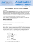
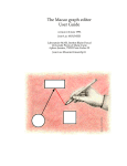
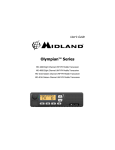
DB1065
User’s Manual
MX465 CTCSS Encoder /
Decoder Development Kit
20480150.001 MX-COM 1996
Table of Contents
1. General Information __________________________________________________ 3
1.1 Introduction _____________________________________________________________
1.2 Warranty _______________________________________________________________
1.3 DB1065 Features_________________________________________________________
1.4 Handling Precautions _____________________________________________________
3
3
4
4
1.4.1 Static Protection _____________________________________________________________ 4
1.4.2 Cleanliness _________________________________________________________________ 4
1.5 Unpacking ______________________________________________________________ 4
2. Electrical Performance ________________________________________________ 4
2.1 Absolute Maximum Ratings ________________________________________________ 4
2.2 Operating Characteristics __________________________________________________ 5
2.3 Prerequisites and Required Equipment ________________________________________ 6
2.3.1 Prerequisites ________________________________________________________________ 6
2.3.2 Power Supply _______________________________________________________________ 6
2.4 Limitations _____________________________________________________________ 6
3. Quick Start __________________________________________________________ 6
3.1 Introduction _____________________________________________________________
3.2 First... _________________________________________________________________
3.3 Second - Setup___________________________________________________________
3.4 Third - Select and Execute a Test ____________________________________________
6
6
6
7
3.4.1 CTCSS encoder verification ____________________________________________________ 7
3.4.2 Transmit audio path verification_________________________________________________ 8
3.4.3 CTCSS decoder verification ____________________________________________________ 8
3.4.4 Receive audio path verification _________________________________________________ 8
4. Fourth - Explore______________________________________________________ 9
4.1 Measuring CTCSS Encoder response time _____________________________________ 9
4.2 Measuring CTCSS Decoder response time_____________________________________ 9
4.3 Measuring CTCSS Decoder band width _______________________________________ 9
4.4 Measuring CTCSS response at different SINADs _______________________________ 9
4.5 Performance at other operating voltages______________________________________ 10
4.6 Connecting the DB1065 to a system _________________________________________ 12
4.7 TIA / EIA 603 __________________________________________________________ 13
5. Hardware __________________________________________________________ 14
5.1 Introduction ____________________________________________________________ 14
5.2 Description ____________________________________________________________ 14
5.2.1 Functional Layout of Circuitry _________________________________________________ 14
5.2.2 Connectors ________________________________________________________________ 14
6. Logic Table for operation______________________________________________ 16
6.1 I/O Conditions __________________________________________________________ 16
6.2 CTCSS Programming ____________________________________________________ 16
7. Troubleshooting _____________________________________________________ 17
7.1 Suggestions ____________________________________________________________ 17
7.2 If you still need help _____________________________________________________ 18
8. Retrofitting from older designs _________________________________________ 18
8.1 Comparison Specifications ________________________________________________ 18
8.2 External Components Comparison __________________________________________ 19
20480150.001 MX-COM 1996
Page 2
9. Schematic __________________________________________________________ 20
10. Component layout___________________________________________________ 21
Table of Figures
FIGURE 1: TEST EQUIPMENT CONNECTIONS
FIGURE 2: COMPOSITE TEST SIGNAL CIRCUIT DIAGRAM
FIGURE 3: TESTING AT DIFFERENT SUPPLY VOLTAGES
FIGURE 4: SUPPLY VOLTAGE VS TYPICAL SUPPLY CURRENT
FIGURE 5: BREAKING OUT SMALL CIRCUIT
FIGURE 6: COMPARISON OF EXTERNAL COMPONENTS FOR OLDER CTCSS ICS
FIGURE 7: DB1065 SCHEMATIC
FIGURE 8: COMPONENT VIEW ASSEMBLY DRAWING
FIGURE 9: SOLDER VIEW ASSEMBLY DRAWING
7
10
11
12
13
19
20
21
22
1. General Information
1.1 Introduction
This manual provides general information to support the installation and operation of the DB1065
Development Kit, a complete test platform to demonstrate and test the MX465 CTCSS encoder/
decoder.
All trademarks and service marks are held by their respective owners.
1.2 Warranty
The DB1065 hardware has been developed and is provided to help designers develop designs
based on the MX465 CTCSS Encoder / Decoder IC. Every reasonable effort has been made to
provide high quality and performance in pursuit of that goal.
Toward that end, MX-COM, Inc. would value any suggestions to improve the DB1065’s manual
and suggestions concerning the DB1065’s hardware design.
Since experiments and designs are the responsibility of the DB1065 user, MX-COM, Inc.’s liability
regarding the use of the DB1065 is in all cases limited to the DB1065 purchase price.
No other warranty is expressed or implied.
20480150.001 MX-COM 1996
Page 3
1.3 DB1065 Features
The DB1065 Development Kit includes many useful features including those highlighted in Table.
Features
Applications
MX•COM MiXed Signal CMOS Design
47 CTCSS Tones + Notone
TX/RX Speech Filters
Parallel Programming using Dip Switch
Serial mode also available
Meets TIA/EIA-603 Land Mobile
Standard
Improved SINAD
Easy µP Interface
Mobile Radio Channel Sharing
Repeater Control
Wireless Intercom Traffic Control
Hookswitch Supervision
Simultaneous Voice Plus Control Signaling
Remote Control
Table 1 DB1065 Features
1.4 Handling Precautions
Like most development boards, the DB1065 is designed for use in office and laboratory
environments. The following practices will help ensure its proper operation.
1.4.1 Static Protection
The DB1065 uses low power CMOS circuits which can be partially or completely damaged by
electrostatic discharge. Partially damaged circuits can function erroneously and provide
misleading test results which can be time consuming (and extremely frustrating) to resolve.
Please observe common industrial static handling precautions when un-packing or handling the
printed circuit board.
1.4.2 Cleanliness
Because some DB1065 circuits are very high impedance, it is important to maintain their
cleanliness. All flux and other contaminants should be thoroughly removed after making any
additions or modifications to the circuit board.
1.5 Unpacking
After reviewing the instructions in section 1.4, Handling Precautions, check to make sure that
each of the following items are provided in the quantities indicated:
Item
1.
2.
3.
Description
DB1065 User’s Manual
DB1065 board
MX465 data sheet
Quantity
1
1
1
2. Electrical Performance
2.1 Absolute Maximum Ratings
Exceeding these maximum ratings can result in damage to the device. Operation of the device
outside the operating limits is not implied.
20480150.001 MX-COM 1996
Page 4
Absolute Maximum Ratings
Min.
Max.
Units
Note
B+ Supply Voltage input
-0.30
25.00
volts DC
+5V Supply Voltage input
-0.30
7.00
volts DC
Voltage on logic inputs or outputs
-0.30
5.30
volts DC
Voltage on analog input or outputs
-0.40
20.00
volts DC
Storage Temperature
0.00
85.00
C
Operating Temperature
0.00
50.00
C
1
2.2 Operating Characteristics
For the following conditions unless otherwise specified:
T=25C, DC supply voltage B+ = +12VDC, GND = 0V
0dB ref. = 750mVrms (VDD = 5VDC)
Composite CTCSS test Signal: 300 mVrms 1KHz test tone, 75 mVrms band limited 6KHz
gaussian white noise, 30 mVrms CTCSS tone
Xtal Frequency = 4.0mhz, 100ppm max
For additional Operation Characteristics refer to MX-COM MX465 data sheet
Characteristic
Supply voltage
B+ DC Supply Voltage Input
+5V DC Supply Voltage Input
DC Supply Current
Minimum
Typical
Maximum
Units
8
3
12
5
25
7
VDC
VDC
6
10
ma
Input Logic specifications for PTT, PTL, CS , MONITOR
Input Low Voltage
1.50
Input High Voltage
3.50
Output Logic Specifications for DECODE (open collector output)
Output Current (sink)
10
Analog Outputs TXOUT, RXOUT, TONEOUT
Impedance
1000
TXOUT Level
RXOUT Level
TONEOUT Level
Analog Inputs TXIN, RXIN
Impedance
TXIN Level
RXIN Level
TX and RX Audio Filter
Total Harmonic Distortion
Output Noise Level (input AC gnd)
Passband
Bandpass Ripple
Passband Gain at 1KHz
CTCSS Decoder
Input signal level
Response Time
Deresponse Time
Upper Decode Band Edge
20480150.001 MX-COM 1996
750
500
300
500
mVrms
mVrms
300
-1
5
3000
1
0
30
180.00
1.005 Fi
mA
1000
2
2
1
1
mVrms
mVrms
mVrms
500
100
30
VDC
VDC
Note
436
250
250
.995 Fi+1
%THD
mVrms
Hz
dB
dB
2
mVrms
ms
ms
Hz
2
3,4,5
3,4,5
3,6
Page 5
Characteristic
Lower Decode Band Edge
Encoder
Tone Output Level
Tone Frequency Accuracy (f error)
Minimum
1.005 Fi-1
Typical
548
-0.30
775
Total Harmonic Distortion
Notes
1
2
3
4
5
6
Maximum
.995 Fi
0.30
2
5
Units
Hz
Note
3,6
mVrms
%fo
%THD
Valid for +5VDC on Vdd to the MX465 IC.
Measured referenced to 0dB= 1KHz tone referenced to 300 mVrms
Composite Signal Test Condition
f0>100Hz (for 100 Hz>f0>67Hz: t=100/f0Hz X 250ms)
Per TIA/EIA-603
Only for the Fi in TIA /EIA-603, where Fi is the program tone.
2.3 Prerequisites and Required Equipment
2.3.1 Prerequisites
In order to effectively use the DB1065 Development Kit, the user should refer to the MX-COM
data sheet for the MX465.
2.3.2 Power Supply
A user provided +12VDC regulated power supply is required to power the development card
when connected to the B+ input. A regulated +5VDC supply is used when powering the DB1065
from the +5V input.
2.4 Limitations
The DB1065 development board is designed to support the serial operation of the MX465 but the
user must design and connect external hardware to use this function in the MX465. Refer to the
MX465 data bulletin for additional assistance for using the MX465 in serial mode. All input and
output analog and logic functions may be evaluated using the parallel mode of operation.
3. Quick Start
3.1 Introduction
This section allows quick setup and test verification of the DB1065 Development Kit.
3.2 First...
Review sections 1.4, Handling Precautions; 1.5, Unpacking and 2.4, Limitations sections above.
(Quick start?!!) Don’t worry, those sections are very short and help you to avoid damaging the
DB1065 or your equipment.
3.3 Second - Setup
a. Connect a +12VDC power supply to B+ and GND.
b. Refer to Figure 1: Test Equipment Connections, on page 7 and Figure 7: DB1065 Schematic,
on page 20 to connect test equipment to the DB1065 development board.
20480150.001 MX-COM 1996
Page 6
DB1065
Terminals
Analog Output
Signals
Connect to
Audio Analyzer,
Meter or
Oscilloscope
+12VDC
Power +
Supply -
Analog Inputs
From Sine wave
generators or
noise source
Optional Serial
Interface
Logic Level
Inputs
Logic Level input or output
Logic level
output
Open Collector
Figure 1: Test Equipment Connections
3.4 Third - Select and Execute a Test
3.4.1 CTCSS encoder verification
a. With the external power supply off, connect an oscilloscope or audio analyzer to TONEOUT.
Ensure test equipment’s ground is tied to GND on the DB1065.
b. Set the dip switches D0-D5 for a CTCSS tone selected from Table 4: CTCSS Tones on page
17.
c. Connect PTT to GND.
d. Apply power.
e. Adjust R3 for an amplitude of 300 mVrms.
f. Measure the amplitude, frequency and or distortion of the CTCSS tone on TONEOUT. The
frequency should correspond to the setting of the dip switch in reference to Table 4: CTCSS
Tones starting on page 17.
20480150.001 MX-COM 1996
Page 7
3.4.2 Transmit audio path verification
a. Using an audio signal generator, set for a 1KHz sine wave at 300 mVrms, connect the audio
signal generator to TXIN.
b. Connect an oscilloscope or audio analyzer to TXOUT.
c. Measure the output level and calculate the gain difference between TXIN and TXOUT.
20*log Vin/Vout where Vin = TXIN and Vout = TXOUT.
d. Calculate the level that represents -3 dB below the output level at TXOUT for a 1khz sine
wave.
3dB
20
TXOUT which equals .707 X TXOUT = -3dB level
e. Lower the frequency of the signal generator until the -3dB level is reached.
f. Measure the output frequency of the signal generator. This will be the lower -3dB band edge of
the TX audio filter.
g. Raise the frequency of the signal generator until the -3dB level is reached.
h. Measure the output frequency of the signal generator. This frequency will be the upper -3dB
band edge of the TX audio filter.
h. Remove ground from PTT . The 1KHz signal applied to TXIN should not be present at the
TXOUT connection.
10
3.4.3 CTCSS decoder verification
a. Remove ground from PTT .
b. Measure the logic level on the MONIT0R output. With no CTCSS tone it should be greater
than 3 volts dc.
c. Connect an audio signal generator to RXIN. Adjust the audio generator’s level to 50 mVrms
and its frequency to equal the CTCSS tone frequency ( 1 hertz ) as set on the dip switch D0-D5
using Table 4: CTCSS Tones starting on page 17.
d. Measure the logic level on the MONIT0R output. It should be less than 1 volt dc when
detecting a CTCSS tone.
e. Connect CARRIER SENSE to +5VDC. MONIT0R output should go to a hi logic level
(>3VDC).
3.4.4 Receive audio path verification
a. Ensure PTT and PTL is not connected to ground.
b. Using an audio signal generator, set for a 1khz sine wave at 300 mVrms, connect the audio
signal generator to RXIN.
c. Connect an oscilloscope or audio analyzer to RXOUT.
d. Measure the output level and calculate the gain difference between RXIN and RXOUT.
20*log Vin/Vout where Vin = RXIN and Vout = RXOUT.
e. Calculate the level that represents -3 dB below the output level at RXOUT for a 1khz sine
wave.
3
20
10 RXOUT or .707 X RXOUT = -3dB level
f. Lower the frequency of the signal generator until the -3dB level is reached.
g. Measure the output frequency of the signal generator. This will be the lower -3dB band edge
of the RX audio filter.
h. Raise the frequency of the signal generator until -3dB level is reached.
i. Measure the output frequency of the signal generator. This will be the upper -3dB band edge of
the RX audio filter.
j. Connect ground to PTL. RX path audio should not be present at the RXOUT connection.
20480150.001 MX-COM 1996
Page 8
4. Fourth - Explore
By using the basic verification tests for receive and transmit, the performance of the MX465 can
be explored by varying the frequency and level of the audio input signals. The following
examples provide additional tests that can be performed.
4.1 Measuring CTCSS Encoder response time
Use the CTCSS encoder verification on page 7 to set up to test encoder response time.
Connect one channel of a storage scope to PTT and another channel of a storage scope to
TONEOUT. Set the scope to trigger on PTT . Connect and disconnect the PTT to ground and
measure the time difference from PTT going from a logic level high to a logic low and a 90%
steady level CTCSS tone amplitude output on TONEOUT.
4.2 Measuring CTCSS Decoder response time
Use the CTCSS decoder verification on page 8 to set up to test decoder response time.
Connect one channel of a storage scope to RXIN and another channel of a storage scope to
MONIT0R . Set the scope to trigger on RXIN. Turn the CTCSS tone off and on by connecting
and disconnecting the signal generator. Measure the time difference from applying CTCSS tone
to RXIN (where the CTCSS tone level reaches 90% of a full steady state level) to MONIT0R
changing from a logic level hi to a logic level low ( were the logic level reaches 90% of steady low
state).
4.3 Measuring CTCSS Decoder band width
Use the CTCSS decoder verification on page 8 to set up to evaluate decoder bandwidth. Adjust
the frequency of the audio generator above and below the CTCSS tone’s center frequency and
measure the band edge where MONIT0R changes from a hi ( indicating no tone present) to a
low ( indicating a CTCSS tone was detected).
4.4 Measuring CTCSS response at different SINADs
A composite signal summing network can be bread boarded to simulate adverse signal
conditions. This consists of an opamp with three summing nodes. Separate signal generators
are used to simulate the 3 basic types of audio signals that may be present at RXAUDIO’s input.
One signal generator is used to simulate the CTCSS tone frequency and level. A noise generator
that is 6khz band limited gaussian noise simulates background noise. The audio sine wave
generator simulates the voice channel. A SINAD meter may be connected to the RXIN audio
path to measure SINAD of the input signal to the MX465’s CTCSS decoder.
20480150.001 MX-COM 1996
Page 9
CTCSS tone
generator
CTCSS tone @
30mvrms
.1uF
Noise
generator
100K
Noise generator @
75mvrms, Band limited
6khz gaussian
.1uF
Audio signal
generator
100K
1khz sine wave @
300mvrms
100K
+Vdd
100K
.1uF
+
+Vdd
100K
.1uF
100K GND
To RXIN and
SINAD meter
Audio Opamp
741 or similar
GND
Figure 2: Composite test signal circuit diagram
Using the circuit above and setting the signal generators to the levels shown in the diagram
simulates a CTCSS signal in a worst case condition. The performance of the DB1065 can be
measured with a SINAD meter connected to RXIN while each signal generator is varied to
simulate different signaling conditions.
4.5 Performance at other operating voltages
The DB1065’s performance may be evaluated at supply voltages other than the +5VDC supplied
from the on board regulator.
a. Turn power supply off.
b. Disconnect the power supply’s connection to J1 the B+ connection on the DB1065.
c. Set the power supply for an output of +5VDC.
d. Turn power supply off and connect it to the +5V J12 of the DB1065.
e. Turn on the power supply.
As an example, a DB1065 was configured to detect a 67Hz CTCSS tone using the following
configuration shown in Figure 3.
20480150.001 MX-COM 1996
Page 10
Oscilloscope
J6 RXOUT audio from
DB1065
CTCSS tone
generator
CTCSS tone @
67Hz, 100mvrms
1K
1KHz sine wave @
300mvrms
Audio signal
generator
DB1065, J2 RXIN
1K
Variable
Power
Supply
0 to +6VDC to J1,
B+ on DB1065
DB1065 +5 and Gnd
connections
GND, J13 on
DB1065
GND, J13 on
DB1065
Ground J5, PTL on
DB1065
Figure 3: Testing at different supply voltages
Measuring supply current at different supply voltages in the configuration shown in Figure 3
would result in a typical graph as shown in Figure 4.
20480150.001 MX-COM 1996
Page 11
DB1065 / MX465 Vdd VS Typical Supply Current
12
11
Typical Supply Current in ma
10
9
8
7
6
5
4
3
2
1
0
0
1
2
3
4
Vdd applied
5
6
7
Figure 4: Supply Voltage Vs Typical Supply Current
Other performance characteristics may be measured and plotted in a similar manner. Please
refer to the MX465’s specifications in section 2, Electrical Performance, on page 3 regarding
maximum and minimum operating limits each device is tested to meet. Section 2’s information is
used by the designer in regard to designing a circuit using the MX465 based on a device’s
electrical properties.
4.6 Connecting the DB1065 to a system
The DB1065 may be connected to a radio system by connecting wires to the terminal strips or the
DB1065’s smaller circuit may be broken out of the development board.
Refer to Figure 5: Breaking Out Small Circuit, on Page 13. Before snapping the smaller circuit
out the traces on the snap lines must be cut by carefully breaking off the three tabs containing the
terminal strips and dip switch. Try and avoid bending or flexing the smaller circuit as the surface
mount components are damaged easily. A set of tin snips can be also be used to cut out the
smaller board and trim up the excess or rough edge left on the smaller board.
Holes for soldering wires have been provided around the edge of the smaller inside circuit. Refer
to Figure 8: Component view Assembly Drawing, to connect wires appropriately. Solder jumpers
in the smaller circuit, E1 through E6, provide a method to select one CTCSS tone for operation.
Refer to Figure 9: Solder View Assembly Drawing, for reference to solder jumpers.
20480150.001 MX-COM 1996
Page 12
#1
Cut traces on
the score line
on both sides
of the PCB with
knife
#2
Snap apart or
cut with tin
snips
#3
Cut traces on
the score line
on both sides
of the PCB with
knife
#4
Snap apart or
cut with tin
snips
#5
#6
Snap apart or
cut with tin
snips
Cut traces on
the score line
on both sides
of the PCB with
knife
Figure 5: Breaking Out Small Circuit
4.7 TIA / EIA 603
Additional performance measurements are detailed in TIA / EIA - 603 standard. Section 6
outlines Standards for Subaudible Signaling for Land Mobile FM or PM Communications
Equipment.
TIA / EIA standards may be obtained from
(TIA’s address)
Telecommunications Industry Association
2001 Pennsylvania Ave. NW
Suite 800
Washington, DC 2006
Phone: (202) 457-5430
Fax: (202) 457-4939
(EIA’s address)
Electronic Industries Association
1722 Eye Street, NW
Suite 440
Washington, DC 20006
Phone: (202) 457-4936
Fax: (202) 457-4966
An alternative source is Global Engineering Documents, 15 Inverness Way East, Englewood, CO
80112 Phone: (800) 854-7179 (They accept Credit card orders) Global is a company that
specializes in reprinting standards and is a good source to quickly get many types of standards.
20480150.001 MX-COM 1996
Page 13
5. Hardware
5.1 Introduction
This section describes the PCB hardware and its adjustment.
5.2 Description
5.2.1 Functional Layout of Circuitry
The block diagram of the MX465 shown below shows internal connections to the MX465. Refer
to Figure 7: DB1065 Schematic, on page 20 for external circuitry on the DB1065 circuit board.
5.2.2 Connectors
Clamping connectors are distributed around the perimeter of the DB1065 motherboard as shown
in Figure 8: Component view Assembly Drawing, on page 21. Silk-screen labels are provided on
the motherboard to identify the connections listed in Error! Reference source not found.. Refer
to Figure 7: DB1065 Schematic, on page 20 in reference to the electrical connections to the
MX465.
20480150.001 MX-COM 1996
Page 14
Name
+B
RXIN
TXIN
Ref.
Desg.
J1
J2
J3
TXOUT
J4
PTL
J5
RXOUT
J6
PTT
TONEOUT
J7
J8
CARRIER
SENSE
DECODE
J9
J10
MONIT0R
J11
+5V
J12
GND
SERIAL DATA
J13
J14
SERIAL CLOCK
J15
LOAD LATCH
J16
Description
This is the positive supply pin usually connected to +12VDC.
This is the input to the audio band pass filter in RX mode.
This is the TX Audio Input pin. In the TX mode it may be pre-filtered, using the
TX audio path, Thus helping to avoid talkoff due to intermodulation of low
frequency speech components with the transmitted CTCSS tone.
This is the band pass filtered transmit audio output pin. In TX mode the pin
outputs audio present at the TX audio input pin.
In RX mode this pin operates as a "Push To Listen" function by enabling the RX
audio path, thus overriding the tone squelch function. Tying PTL to ground will
inhibite audio through the RX audio path till a CTCSS tone is decoded or “No
Tone” is selected on D0-D5
This is the band pass filtered receive audio output pin. This pin outputs audio
when RX tone DECODE is true or PTL is true or when Notone is programmed.
Logic level input pulled low to enable transmitt mode.
The CTCSS sine wave output appears on this pin under control of the PTT
input. The level is adjusted using R3.
Input that can be connected to the radios carrier sense logic to enable the
CTCSS decoder only when a carrier is present.
This is an open collector output used to mute the RX audio path or control
squelch circuitry in a system. It provides a path to ground when a CTCSS tone is
not present and is open collector when a CTCSS tone is detected.
This pin will have a +5VDC output till a CTCSS tone is detected. Alternatively
this pin can be used to disable the open collector DECODE output pin and can
be connected to a system’s "Push To Listen", or MONIT0R function.
This pin is an alternative supply pin that can be connected to an external DC
supply to evaluate performance of the MX465 at supply voltages below 7.0 VDC.
Connection to ground.
In serial operation, Data to control the MX465 is clocked in on this logic input.
Refer to the MX465’s data sheet for operation.
Control data is clocked into the MX465 based on the rising and falling edge of
this logic input.
Data is either in the process of loading into the MX465 control registers or is
latched into the MX465’s internal registers using this logic input pin.
Table 2: Connector Signal Descriptions
20480150.001 MX-COM 1996
Page 15
6. Logic Table for operation
6.1 I/O Conditions
Output Pin
Condition
Input Pin Condition
D0-D5
PTT
CTCSS
PTL
Result/Function
DECODE
Tone
Tone
Decoder
Enabled
RX Audio
Path
Enabled
Notes
Enabled
TX Audio
Path
Enabled
MONIT0R Transmitter
Tone in
Tone
0
0
X
0
1
Yes
Yes
No
No (bias)
1
No Tone
0
X
X
0
1
No (bias)
Yes
No
No (bias)
2
Tone
1
0
No
0
1
No (bias)
No
Yes
No (bias)
3a
Tone
1
1
No
0
1
No (bias)
No
Yes
Yes
3b
Tone
1
X
Yes
o/c
0
No (bias)
No
Yes
Yes
4
No Tone
1
X
X
o/c
0
No (bias)
No
Yes
Yes
5
Table 3: Combinations of input/output conditions
Notes: o/c = Open circuit
X = don’t care
1. Normal tone transmit condition.
2. Notone programmed in TX mode, tone transmit O/P set to VDD/2. TX audio path enabled.
3a. Normal decode standby.
3b. Normal decode standby with PTL used to enable audio.
4. Normal decode of correct CTCSS tone condition, PTL has no effect.
5. Notone programmed in RX mode, tone transmit O/P (o/c). RX audio path enabled.
6.2 CTCSS Programming
Tone
Programming Inputs, Switch (Solder Jumper)
Nominal
Frequency (Hz)
MX465
Frequency (Hz)
f0 (%)
D5
(E6)
D4
(E5)
D3
(E4)
D2
(E3)
D1
(E2)
D0
(E1)
Hex
67.0
69.3
71.9
74.4
77.0
79.7
82.5
85.4
88.5
91.5
94.8
97.4
100.0
103.5
107.2
110.9
66.98
69.32
71.901
74.431
76.965
79.677
82.483
85.383
88.494
91.456
94.76
97.435
99.96
103.429
107.147
110.954
-0.029
0.024
0.001
0.042
-0.046
-0.029
-0.021
-0.020
-0.007
-0.048
-0.042
-0.036
-0.040
-0.069
-0.05
0.049
1
1
0
1
0
1
0
1
0
1
0
1
0
0
0
0
1
1
1
1
0
1
1
1
0
1
1
1
0
1
0
1
1
1
1
1
1
1
1
1
1
1
1
1
1
1
1
1
1
0
1
1
1
1
1
1
1
0
1
0
1
1
1
0
1
0
1
1
1
0
1
0
1
1
0
1
0
0
0
1
1
1
1
0
1
1
0
0
0
1
1
0
1
0
0
1
3F
39
1F
3E
0F
3D
1E
3C
0E
3B
1D
3A
0D
1C
0C
1B
20480150.001 MX-COM 1996
Page 16
Tone
•
•
•
•
•
•
•
•
•
Programming Inputs, Switch (Solder Jumper)
Nominal
Frequency (Hz)
MX465
Frequency (Hz)
f0 (%)
D5
(E6)
D4
(E5)
D3
(E4)
D2
(E3)
D1
(E2)
D0
(E1)
Hex
114.8
118.8
123.0
127.3
131.8
136.5
141.3
146.2
151.4
156.7
159.8
162.2
167.9
173.8
179.9
183.5
186.2
189.9
192.8
196.6
199.5
203.5
206.5
210.7
218.1
225.7
229.1
233.6
241.8
250.3
254.1
Notone
Serial input mode
114.84
118.793
123.028
127.328
131.674
136.612
141.323
146.044
151.441
156.875
159.936
162.311
167.708
173.936
179.654
183.680
186.289
190.069
192.864
196.329
199.312
203.645
206.207
210.848
217.853
225.339
229.279
233.359
241.970
250.282
254.162
0.035
-0.006
0.023
0.022
-0.095
0.082
0.016
-0.107
0.027
0.112
0.085
0.069
-0.114
0.078
-0.137
0.098
0.048
0.089
0.033
-0.138
-0.094
0.071
-0.142
0.070
-0.113
-0.160
0.078
-0.103
0.070
-0.007
0.024
N/A
N/A
0
0
0
0
0
0
0
0
0
0
1
0
0
0
0
1
0
1
0
1
1
0
1
0
0
0
1
0
0
0
1
1
1
0
1
0
1
0
1
0
1
0
1
1
0
1
0
1
1
0
1
1
1
1
0
1
1
0
1
1
0
1
0
1
1
0
1
1
1
1
1
1
1
0
0
0
0
0
0
0
0
0
0
0
0
0
0
0
0
0
0
0
0
0
0
0
1
0
Data
0
0
0
0
0
0
0
1
1
1
0
1
1
1
1
0
1
0
0
1
1
0
1
0
0
0
1
0
0
0
0
0
Clock
1
1
1
0
0
0
0
1
1
1
0
1
0
0
0
1
0
1
1
0
0
1
1
1
1
0
1
0
0
0
0
0
X
1
0
0
1
1
0
0
1
1
0
1
0
1
1
0
0
0
1
1
0
1
1
0
0
0
1
1
1
0
0
0
0
X
0B
1A
0A
19
09
18
08
17
07
16
31
06
15
05
14
32
04
33
13
34
35
03
36
12
02
11
37
01
10
00
38
30
2X
Not specified in the TIA/EIA tone set
Table 4: CTCSS Tones
7. Troubleshooting
Ideally, this section would not be required...however, sometimes the least expected (OK, the
undesired) occurs. This section is intended to answer the most common questions and provide
some helpful troubleshooting suggestions.
7.1 Suggestions
Use an oscilloscope
Because transmit and receive are biased a.c. signals, an oscilloscope is an invaluable
troubleshooting tool to probe and verify signal levels
Check for loose connections or jumpers
20480150.001 MX-COM 1996
Page 17
Make sure the power supplies used are sufficiently noise free. Also make sure there are no
unintended noise sources radiating into the test setup.
7.2 If you still need help
If you have read this section, reexamined your test setup, and still cannot figure out what is
wrong, please contact us for additional assistance. Please be ready to describe the problem or
symptoms and the steps you have taken to try to correct them. We can be reached at
MX-COM, Inc.
4800 Bethania Station Rd.
Winston-Salem, NC 27105-1201
telephone (910) 744-5050
telephone (800) 638-5577
fax (910) 744-5054
8. Retrofitting from older designs
The following is a brief list of differences between older generation MX-COM CTCSS
encoder/decoders and the MX465. For full details refer to each device’s individual data sheets.
8.1 Comparison Specifications
MX365
MX365A
MX165A
MX165B
CTCSS
TONES
38 + No tone
37 = EIA 220
A
plus 97.4Hz
39 + No Tone
37 = EIA 220
B
plus 69.3Hz
& 97.4Hz
39 + No Tone
37 = EIA 220
B
plus 69.3Hz &
97.4Hz
39 + No Tone
39= TIA/EIA
603
Supply
Voltage
Min: 4.5V
Typ: 5.0V
Max: 5.5V
Min: 4.5V
Typ: 5.0V
Max: 5.5V
Min : 3.0V
Typ: 3.75V
Max: 4.5V
Min: 3.0V
Typ: 3.75V
Max: 4.5V
0dB ref
Composite
Signal
300mVrms
0dB 1kHz test
tone, -12dB
noise (band
limited 6kHz
gaussian
white noise), 20dB f0
CTCSS tone.
20480150.001 MX-COM 1996
308mVrms
0dB 1kHz test
tone, -12dB
noise (band
limited 6kHz
gaussian
white noise), 20dB f0
CTCSS tone.
100mVrms
0dB 1kHz test
tone, -12dB
noise (band
limited 6kHz
gaussian
white noise), 20dB f0
CTCSS tone.
100mVrms
1kHz test
tone at
300mVrms,
75mVrms
noise (band
limited 6kHz
gaussian
white noise),
30mVrms
CTCSS tone.
MX165C
MX465
47 + No Tone 47 + No Tone
39 = TIA/EIA
39 = TIA/EIA
603 plus
603 plus
159.8Hz,
159.8Hz,
183.5Hz,
183.5Hz,
189.9Hz,
189.9Hz,
196.6Hz,
196.6Hz,
199.5Hz,
199.5Hz,
206.5Hz,
206.5Hz,
229.1Hz,
229.1Hz,
254.1Hz
254.1Hz
Min: 2.75V
Min: 2.75V
Typ:
Typ:
3.75/5.0V
3.75/5.0V
Max: 5.5V
Max: 5.5V
750mVrms
750mVrms
0dB 1kHz test 0dB 1kHz test
tone, -12dB
tone, -12dB
noise (band
noise (band
limited 6kHz
limited 6kHz
gaussian
gaussian
white noise), - white noise), 20dB f0
20dB f0
CTCSS tone.
CTCSS tone.
Page 18
8.2 External Components Comparison
Figure 6: Comparison of External Components for Older CTCSS ICs
EXTERNAL
COMPONENTS
MX365
MX365A
MX165A
MX165B
MX165C
MX465
R1
R2
R3
X1
C1
C2
C3
C4
C5
C6
C7
C8
C9
C10
C11
D1
1M
560k
820k
1MHz
0.1uF
68pF
33pF
0.1uF
0.1uF
0.47uF
0.1uF
0.1uF
0.1uF
0.1uF
0.1uF
Small signal
1M
560k
820k
1MHz
0.1uF
68pF
33pF
0.1uF
0.1uF
0.47uF
0.1uF
0.1uF
0.1uF
0.1uF
0.1uF
Small signal
1M
560k
820k
1MHz
0.1uF
68pF
33pF
0.1uF
0.1uF
0.47uF
0.1uF
0.1uF
0.1uF
0.1uF
0.1uF
Small signal
1M
560k
820k
1MHz
0.1uF
68pF
33pF
0.1uF
0.1uF
0.47uF
0.1uF
0.1uF
0.1uF
0.1uF
0.1uF
Small signal
4.7M
560k
820k
1MHz
0.1uF
18pF
33pF
0.1uF
0.1uF
0.47uF
0.1uF
0.1uF
0.1uF
0.1uF
0.1uF
Small signal
4.7M
560k
820k
4MHz
0.1uF
18pF
33pF
0.1uF
0.1uF
0.47uF
0.1uF
0.1uF
0.1uF
0.1uF
0.1uF
Small signal
Resistors 10%, Capacitors 20%, Xtal 100ppm max
Note : The values specified for R1, C2 and C3 have been found to be satisfactory when used with a
crystal (X1) whose equivalent series resistance is to 1000 ohms. The crystal manufacturer should be
consulted to determine optimum values for different crystals.
20480150.001 MX-COM 1996
Page 19
9. Schematic
Figure 7: DB1065 Schematic
20480150.001 MX-COM 1996
Page 20
10. Component layout
Figure 8: Component view Assembly Drawing
20480150.001 MX-COM 1996
Page 21
Figure 9: Solder View Assembly Drawing
20480150.001 MX-COM 1996
Page 22
CML Microcircuits
COMMUNICATION SEMICONDUCTORS
CML Product Data
In the process of creating a more global image, the three standard product semiconductor
companies of CML Microsystems Plc (Consumer Microcircuits Limited (UK), MX-COM, Inc
(USA) and CML Microcircuits (Singapore) Pte Ltd) have undergone name changes and, whilst
maintaining their separate new names (CML Microcircuits (UK) Ltd, CML Microcircuits (USA)
Inc and CML Microcircuits (Singapore) Pte Ltd), now operate under the single title CML
Microcircuits.
These companies are all 100% owned operating companies of the CML Microsystems Plc
Group and these changes are purely changes of name and do not change any underlying legal
entities and hence will have no effect on any agreements or contacts currently in force.
CML Microcircuits Product Prefix Codes
Until the latter part of 1996, the differentiator between products manufactured and sold from
MXCOM, Inc. and Consumer Microcircuits Limited were denoted by the prefixes MX and FX
respectively. These products use the same silicon etc. and today still carry the same prefixes.
In the latter part of 1996, both companies adopted the common prefix: CMX.
This notification is relevant product information to which it is attached.
CML Microcircuits (USA) [formerly MX-COM, Inc.] Product Textual Marking
On CML Microcircuits (USA) products, the ‘MX-COM’ textual logo is being replaced by a ‘CML’
textual logo.
Company contact information is as below:
CML Microcircuits
(UK)Ltd
CML Microcircuits
(USA) Inc.
CML Microcircuits
(Singapore)PteLtd
COMMUNICATION SEMICONDUCTORS
COMMUNICATION SEMICONDUCTORS
COMMUNICATION SEMICONDUCTORS
Oval Park, Langford, Maldon,
Essex, CM9 6WG, England
Tel: +44 (0)1621 875500
Fax: +44 (0)1621 875600
[email protected]
www.cmlmicro.com
4800 Bethania Station Road,
Winston-Salem, NC 27105, USA
Tel: +1 336 744 5050,
0800 638 5577
Fax: +1 336 744 5054
[email protected]
www.cmlmicro.com
No 2 Kallang Pudding Road, 09-05/
06 Mactech Industrial Building,
Singapore 349307
Tel: +65 7450426
Fax: +65 7452917
[email protected]
www.cmlmicro.com
D/CML (D)/2 May 2002