1
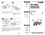
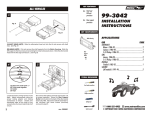
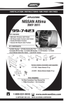
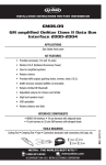
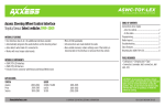
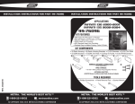
KIT FEATURES
4
Shaft and
DIN unit
provisions
Fig. A
Equalizer
provisions
99-7407
INSTALLATION
INSTRUCTIONS
KIT COMPONENTS
Fig. B
Radio Housing
IF AN EQUALIZER WILL BE INCLUDED: Slide the aftermarket equalizer into the back of the
Radio Housing. Using the hardware included with the equalizer, mount the unit to the kit.
(see Fig. A)
IF AN EQUALIZER WILL NOT BE INCLUDED: Snap the Equalizer Dummy Plate into the
Radio Housing. (see Fig. B)
Faceplate
#1
5
A
APPLICATIONS
CAR
PAGE
NISSAN
240SX 1989-94........................................................... 1
Maxima 1989-94.........................................................1
Stanza 1987-89...........................................................2
6
Faceplate
#2
B
C
D
Equalizer
Dummy Plate
A) Strip wire ends back ½"
B) Twist ends together
C) Solder
D) Tape
Locate the factory wiring harness in the
dash. Metra recommends using the
proper mating adaptor and making
connections as shown. (Isolate and
individually tape off the ends of any
unused wires to prevent electrical short
circuit).
TOOLS REQUIRED
Re-connect the battery terminal and test the unit
for proper operation. Mount the head unit/kit
assembly to the sub-dash with (4) screws
previously removed in step #1.
Phillips screwdriver
Cutting tool
1-800-221-0932
3
rev. 100103
Wrench
www.metraonline.com
© COPYRIGHT 2001 METRA ELECTRONICS CORPORATION
NISSAN 240SX 1989-94
1
NISSAN Stanza 1987-89
2
"C"
1
2
"A"
Fig. A
Fig. A
"A"
"C"
Fig. B
Fig. B
Disconnect the negative battery terminal to
prevent an accidental short circuit. Unclip
the gear shifter/radio trim bezel and remove
the bezel. Remove (4) Phillips screws
securing the factory head unit and
disconnect the wiring.
Cut and remove all mounting tabs on the
Radio Housing EXCEPT tabs "C". The
mounting tabs can be identified by the
stamped letter on the back of each tab. (see
Fig. A). Cut and remove the side portion of
Faceplate #1. (see Fig. B). Skip to the
Installation Instructions for ALL VEHICLES
on Page #2.
Disconnect the negative battery terminal to
prevent an accidental short circuit. Remove
the ashtray. Remove (2) screws from the
base of the radio trim bezel. Remove (2)
screws above the climate controls. Unclip
the radio trim bezel and remove. Remove
(4) screws securing the factory head unit
and disconnect the wiring.
Cut and remove all mounting tabs on the
Radio Housing EXCEPT tabs "A". The
mounting tabs can be identified by the
stamped letter on the back of each tab. (see
Fig. A). Locate Faceplate #1. (see Fig. B).
Skip to the Installation Instructions for ALL
VEHICLES on Page #2.
NISSAN Maxima 1989-94
1
ALL VEHICLES
2
"B"
3
Fig. A
Fig. A
Fig. B
Disconnect the negative battery terminal to
prevent an accidental short circuit. Remove
(2) Phillips screws above the radio opening.
Remove the ashtray and (2) screws
exposed in the ashtray cavity. Unclip the top
of the dash trim bezel and remove. Remove
(4) screws securing the factory head unit
and disconnect the wiring.
1
Cut and remove all mounting tabs on the
Radio Housing EXCEPT tabs "B". The
mounting tabs can be identified by the
stamped letter on the back of each tab. (see
Fig. A). Locate Faceplate #2. (see Fig. B).
Skip to the Installation Instructions for ALL
VEHICLES on Page #2.
Fig. B
2-SHAFT HEAD UNITS: Attach the Faceplate to the Radio Housing. Slide the aftermarket
head unit into the kit and secure with shaft nuts. (see Fig. A)
DIN HEAD UNITS: Cut and remove the shaft supports from the Faceplate and Radio
Housing. Attach the Faceplate to the Housing. Slide the DIN cage into the kit and secure by
bending the metal locking tabs down. Slide the aftermarket head unit into the cage until
secure. (see Fig. B)
2