1
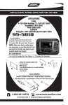
INSTALLATION INSTRUCTIONS FOR PART 95-7326
APPLICATIONS
Hyundai Elantra 2007-2010
(US Model Only)
(Non Radio Delete)
(Non Touring Model)
95-7326
KIT FEATURES
• Double DIN Radio Provision
• Stacked ISO Mount Units Provision
KIT COMPONENTS
A) Double DIN Trim Plate B) Double DIN Brackets
A
B
TOOLS REQUIRED:
Small Flat Blade Screwdriver/ Panel Removal Tool
• Phillips Screwdriver
1-800-221-0932
www.metraonline.com
© COPYRIGHT 2010 METRA ELECTRONICS CORPORATION
95-7326
TABLE OF CONTENTS
Dash Disassembly
- Hyundai Elantra 2007-2010 . . . . . . . . . . . . . . . . . . . . . . . . . . . . . . . . . . . . . . . . 1
Kit Assembly
- Double DIN Radio Provision . . . . . . . . . . . . . . . . . . . . . . . . . . . . . . . . . . . . . . . 2
- Stacked ISO Mount Units Provision . . . . . . . . . . . . . . . . . . . . . . . . . . . . . . . . . 3
Final Assembly . . . . . . . . . . . . . . . . . . . . . . . . . . . . . . . . . . . . . . . . . . 4
*Note:
Refer also to the instructions included with the aftermarket radio.
95-7326 DASH DISASSEMBLY
HYUNDAI ELANTRA 2007-2010
A
1 Disconnect the negative battery terminal to prevent an accidental short
circuit.
2 Unclip and remove the panel surrounding the radio including the a/c
vents and hazard button. (Figure A)
3 Remove (4) Phillips screws to remove
radio. (Figure B)
A/C
1 2
3
4
Continue to kit assembly.
B
1
95-7326 KIT ASSEMBLY
DOUBLE DIN RADIO PROVISION
*Note: Refer also to the instructions included with the aftermarket radio.
A
1 Cut and remove the bar in the factory
radio trim panel. (Figure A)
TIP: The smoother the cut, the better
the 95-7326 will look in the dash panel.
CUT OUT BAR
2 Snap the Double DIN brackets to the
inside edge of the Double DIN trim
plate. (Figure B)
CUT HERE
3 Slide the Double DIN radio into the
bracket/trim plate assembly and
secure the radio to the assembly using
the screws supplied with the radio.
(Figure C)
B
Continue to final assembly.
C
2
95-7326 KIT ASSEMBLY
STACKED ISO MOUNT UNITS PROVISION
*Note: Refer also to the instructions included with the aftermarket radio.
A
1 Cut and remove the bar in the factory
radio trim panel. (Figure A)
TIP: The smoother the cut, the better
the 95-7326 will look in the dash panel.
CUT OUT BAR
2 Snap the Double DIN brackets to the
inside edge of the Double DIN trim
plate. (Figure B)
CUT HERE
3 Slide the stacked ISO units into the
bracket/trim plate assembly and
secure the units to the assembly using
the screws supplied with the units.
(Figure C)
B
Continue to final assembly.
C
3
95-7326 FINAL ASSEMBLY
FINAL ASSEMBLY
A
(A) Strip wire ends back 1/2"
B
B) Twist ends together
C) Solder
C
D) Tape
D
1 Locate the factory wiring harness in the dash. Metra recommends using the
proper mating adapter and making connections as shown. (Isolate and individually tape off the ends of any unused wires to prevent electrical short circuit.)
2 Re-connect the negative battery terminal and test the unit for proper operation.
3 Reassemble radio and dash assemblies in reverse order of disassembly.
FINAL WIRING CONNECTIONS
Make wiring connections using the EIA color code chart shown below and the instructions included with the
head unit. Metra recommends making connections as shown below; Strip, Splice, Solder, Tape. Isolate and
individually tape off ends of any unused wires to prevent electrical short circuit.
METRA / EIA WIRING CODE
12V Ignition / Acc. . . . . . . . . . Red
Right Front (+) . . . . . . . . . . . . Gray
12V Batt / Memory. . . . . . . . . Yellow
Right Front (-). . . . . . . . . . . . . Gray/ Black
Ground. . . . . . . . . . . . . . . . . . Black*
Left Front (+) . . . . . . . . . . . . . White
Power Antenna. . . . . . . . . . . . Blue
Left Front (-). . . . . . . . . . . . . . White / Black
Amp Turn-On . . . . . . . . . . . . . Blue / White
Right Rear (+) . . . . . . . . . . . . Violet
Amp Ground. . . . . . . . . . . . . . Black / White
Right Rear (-) . . . . . . . . . . . . . Violet / Black
Illumination . . . . . . . . . . . . . . Orange
Left Rear (+) . . . . . . . . . . . . . Green
Dimmer . . . . . . . . . . . . . . . . . Orange / White
Left Rear (-) . . . . . . . . . . . . . . Green / Black
*NOTE: When a Black wire is not present, ground radio to vehicle chassis.
All colors may not be present on all leads due to manufacturer’s specifications.
4
95-7326
NOTES
5
95-7326 INSTRUCTIONS
1-800-221-0932
www.metraonline.com
REV. 4/27/10 © COPYRIGHT 2010 METRA ELECTRONICS CORPORATION
INST95-7326