1
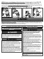
Aussie
Adventurer
TM
PORTABLE LP Gas Grill
Pre-Assembled Grill
Owner’s and Use Manual
This Owners Manual for use with Models:
2400 with Side Table
2410 with Side Burner
2420 with Side Table and Lantern
2430 with Side Burner and Lantern
2440 with Side Burner, Lantern and Carry Bag
MODEL 2430 shown
(LP Cylinders not included)
FOR OUTDOOR HOUSEHOLD USE ONLY. NOT FOR COMMERCIAL USE.
For Customer Service, call 1-800-251-7558 or visit our website at www.meco.net
• Failure to follow these instructions could result in fire or explosion which could cause death,
serious personal injury, or property damage.
• Read and follow instructions carefully before assembly or use.
• Do not use this product for any other purpose than which it is intended.
• These instructions must be kept with the user. SAVE THESE INSTRUCTIONS.
FOR YOUR SAFETY
If you smell gas:
1. Do not attempt to light appliance.
2. Extinguish any open flame.
3. Disconnect from fuel supply.
FOR YOUR SAFETY
1. Do not store or use gasoline or other
flammable vapors and liquids within 25 feet
(7.62m) of this or any other appliance.
2. An LP cylinder not connected for use shall not
be stored within 10 feet (3.05m) in the vicinity
of this or any other appliance.
3. Do not store any LP gas cylinder indoors.
CONTENTS
I. Assembly Instructions.......................................................2
A) Parts Illustrations...........................................................3
B) Parts List........................................................................4
C) Setting up Your Grill.......................................................5
1) Standing Grill On Legs...............................................5
2) Side Table Assembly..................................................7
3) Side Burner Table Assembly.....................................7
4) Lantern Assembly......................................................8
a) Assemble Mantle to Burner....................................8
b) Pre-burn Mantle.....................................................8
c) Assemble Lantern to Gas Tube..............................9
d) Assemble Lantern/Gas Tube to Grill.......................9
5) Install Grease Container............................................9
D) Connecting/Disconnecting LP Cylinder.......................10
1) Installation Codes....................................................10
2) LP Cylinder..............................................................10
3) Hoses & Regulator...................................................10
II. Operating and Maintaining Your LP Gas Grill...............11
A) Before Using Your Grill..............................................11
1) Using Gas................................................................11
2) Selecting a Location...............................................11
3) Performing a Leak Test............................................12
B) Lighting the Gas Grill.................................................13
1) Ignition Lighting Main Grill........................................13
2) Manual Lighting Main Grill........................................13
3) Ignition Lighting the Side Burner..............................14
4) Manual Lighting the Side Burner.............................14
5) Ignition Lighting the Lantern ...................................15
6) Manual Lighting the Lantern ...................................15
7) Check Your Flame...................................................15
C) Operating the Gas Grill..............................................16
1) Grill Cooking............................................................16
2) End of Cooking Session..........................................17
D) Care and Maintenance...............................................17
1) Cleaning the Grill.....................................................17
a) Grease Container... ............................................17
b) Cooking Grid.......................................................17
c) Hood and Bowl....................................................17
d) Burners................................................................17
2) Storage and Transport............................................19
III. Troubleshooting...............................................................20
V. Limited Warranty..............................................................22
— NOTICE —
MECO CORPORATION STRIVES TO BE A QUALITY SUPPLIER OF CONSUMER PRODUCTS. IF
WE OMITTED ANY PARTS NEEDED FOR ASSEMBLY, OR YOU NEED TROUBLESHOOTING
INFORMATION, PLEASE CONTACT US USING OUR TOLL FREE NUMBER. THANK YOU FOR
PURCHASING A MECO CORPORATION PRODUCT.
1-(800)-251-7558
8 am - 6 pm E.S.T Mon. - Fri.
1-(423)-639-1171 (TELEPHONE)
1-(423)-639-2570 (FAX)
www.meco.net
CONSUMER SERVICE DEPARTMENT
MECO CORPORATION
1500 INDUSTRIAL ROAD
GREENEVILLE, TN. 37745 USA
CARBON MONOXIDE HAZARD
This appliance can produce carbon monoxide
which has no odor.
Using it in an enclosed space can kill you.
Never use this appliance in an enclosed space,
such as a camper, tent, car or home.
PREPARATION FOR ASSEMBLY: Note: This Grill is
pre-assembled. Only the accessary items need to be
attached.Remove Grill and all the packaging from carton and
place on floor. Make sure there are no loose parts. Note:
Before using your grill, read the instructions and your
manual. For easier set-up assembly, follow instructions of
each step in the order they are written as you look at the
diagrams. If your model grill does not have the accessories
indicated in the assembly steps, skip that step and proceed to
the next step that applies to your model.
ASSEMBLY INSTRUCTIONS
To reduce the risk of serious bodily injury or death:
·The use of alcohol, prescription or non-prescription
drugs could impair the consumer’s ability to properly
assemble or safely operate this appliance.
·Do not connect LP cylinders until assembly is complete.
If you need replacement parts, look in the Parts List Section
to find the exact parts you need. If you have any questions or
need help, contact our Customer Service. Be sure to mention
the grill model number located on right side of the grill body.
©Meco Corporation® 2005
2
Parts Replacement Illustrations
1
3
2
11
10
6
5
4
7
8
9
13
12
15
14
20
16
17
18
19
21
23
25
24
22
26
30
31
27
28
29
36
32
37
35
34
33
39
40
42
38
41
3
46
43
47
45
44
50
51
48
49
58
52
53
56
55
54
57
59
62
60
61
PARTS LIST
ITEM DESCRIPTION
1
2
3
4
5
6
7
8
9
10
11
12
13
14
15
16
17
18
19
20
21
22
23
24
25
26
27
28
PART #
Owner's Manual
Hood w/Hinges
Screw, M6x9 Shoulder (Hood Hinge)
Hinge, Hood
Screw, M5x10mm (Hood Hinge Bracket)
Nut, M5 Hex Washer Head (Hood Hinge)
Screw, M5x15 (Hood Handle)
Hood Handle
Hood Badge
Hood Latch
Screw, M5x12mm (Upper Leg)
Bracket, Leg
Screw, ST4.8 x 25mm Type A (Leg Bracket)
Assy, Leg Bracket Assy
Assy, Leg
Screw, ST4.8x10mm Type B (Leg/Bowl Bracket)
Screw, ST4.8x10mm Type A (Leg Lock)
Leg Lock
Leg Foot
Screw, ST4.8x45mm Type B (Leg Foot)
Bowl Pan
Post Support, Bowl Pan
Grease Container
Cooking Grid
Bracket, Body Hinge Bracket
Body/Leg Assembly
Screw, M6x15mm (Body Carry Handle)
Handle, Body Carry
4
03.6506.00
03.6506.01
03.6506.02
03.6506.03
03.6237.00
03.6506.04
03.6506.05
03.6506.06
03.6506.07
03.6506.08
03.6506.09
03.6506.10
03.6506.11
03.6506.12
03.6506.13
03.6506.14
03.6506.15
03.6506.16
03.6506.17
03.6506.18
03.6506.19
03.6506.20
03.6506.21
03.6506.22
03.6506.23
03.6506.24
03.6506.25
03.6506.26
QTY
MODEL MODEL MODEL MODEL MODEL
2400
2410
2420
2430
2440
1
1
2
1
3
3
2
1
1
1
6
3
9
3
3
20
6
3
3
3
1
4
1
1
1
1
2
1
1
1
2
1
3
3
2
1
1
1
6
3
9
3
3
20
6
3
3
3
1
4
1
1
1
1
2
1
1
1
2
1
3
3
2
1
1
1
6
3
9
3
3
20
6
3
3
3
1
4
1
1
1
1
2
1
1
1
2
1
3
3
2
1
1
1
6
3
9
3
3
20
6
3
3
3
1
4
1
1
1
1
2
1
1
1
2
1
3
3
2
1
1
1
6
3
9
3
3
20
6
3
3
3
1
4
1
1
1
1
2
1
QTY
PARTS LIST (CONT'D)
ITEM DESCRIPTION
29
30
31
32
33
34
35
36
37
38
39
40
41
42
43
44
45
46
47
48
49
50
51
52
53
54
55
56
57
58
59
60
61
62
PART #
Heat Shield
Screw, ST3.8x6mm (Heat Shield)
Guide Bracket, Main Burner
Screw, M4x10mm (M. Burner/S. Burner Electrode)
Main Burner
Wire, Main Burner Ground
Nut, M4 Hex (Main Burner/Ground Wire)
Piezo
Electrode, Main Burner
Knob, Main Burner
Valve/Hose/Regulator, Main burner
Level Vial
Side Table Accessory
Grid, Side Burner
Side Burner/Table Accessory (Replacement)
Cover, Side Burner/Table
Knob, Side Burner
Screw, M3.5x8mm Torx (Side Burner Valve)
Valve Assembly, Side Burner
Pin, Cotter 1.6mmx28mm (Side Burner Valve)
Electrode, Side Burner
Burner, Side
Lantern Gas Tube
Lantern
Cover, Lantern Top
Globe, Lantern
Mantle, Lantern
Screw, #10x3/4" Type 25 Csk (Lantern Knob)
Knob, Lantern
Screw, #4-24x3/8" Type 25 (Lantern Housing)
Electrode/Piezo, Lantern
Pushbutton, Lantern
Lantern/Gas Tube Accessory
Carry Bag Accessory
03.6506.27
03.6506.28
03.6506.29
03.6506.30
03.6506.31
03.6506.32
03.6506.33
03.6260.01
03.6506.34
03.6506.35
03.6506.36
03.6506.37
03.6506.38
1210.5.001
1220.5.001
03.6506.39
03.6506.40
03.6506.41
03.6506.42
03.6235.00
03.6506.43
03.6506.44
03.6506.45
03.6506.46
03.6506.47
03.6506.48
03.6506.49
03.6506.50
03.6506.51
03.6506.53
03.6506.54
03.6506.55
1230.5.001
1240.5.001
MODEL MODEL MODEL MODEL MODEL
2400
2410
2420
2430
2440
1
2
1
4
1
1
2
1
1
1
1
1
All
---All
---------------------------------------------------All
All
1
2
1
4
1
1
2
2
1
1
1
1
All
1
All
1
1
2
1
2
1
1
------------------------------All
All
1
2
1
4
1
1
2
1
1
1
1
1
All
---All
---------------------1
1
1
1
2
1
1
2
1
1
All
All
1
2
1
4
1
1
2
2
1
1
1
1
All
1
All
1
1
2
1
2
1
1
1
1
1
1
2
1
1
2
1
1
All
All
1
2
1
4
1
1
2
2
1
1
1
1
All
1
All
1
1
2
1
2
1
1
1
1
1
1
2
1
1
2
1
1
All
All
SETTING UP YOUR GRILL
To reduce the risk of a cut or pinching injury:
· Wear protective gloves when handling parts that have
sharp edges.
· When opening legs, keep hands and fingers away from
the three body leg mount areas to avoid pinching. (See
FIG. 2A)
Release Hood Latch
Level Indicator
STANDING GRILL ON LEGS
STEP 1) With your grill flat on the floor, release the
Hood latch from the Hood Handle. (FIG. 1) Open
Hood and remove any accessories from the grid
that are with your model. Do not remove anything
else at this step. Close and re-latch the hood.
Fig. 1
5
STEP 2) Lift grill up at one leg mount. Release the
spring lever at each leg foot. (FIG. 2A) Swing each
leg all the way out one at a time, and let it rest on
the floor. (FIG. 2B, 2C & 2D) The last leg will allow
the grill to stand by itself. This is the lower height
for use.
Leg Pinch area
FIG. 3B
1 1’4”
FIG. 3D
FIG. 3C
Depress Leg Button
Spring Lever
STEP 4) If the grill is not standing level, the legs
can be adjusted to level it. There are 3 adjustments
within a range of 1 1/4” from the fully extended leg
in which to level the grill.
FIG. 2A
While supporting the grill, depress the round leg
button with your thumb on the leg or legs that need
to be adjusted. (FIG. 3C & 3D) Slide the leg in or
out until you find the setting that best allows leveling. You will hear a light click at each setting when
extending the leg. Check the grill level by the level
indicator located to the left of the Main Grill control
knob. (See FIG. 1 page 5)
FIG. 2C
FIG. 2B
STEP 5) Unlatch the hood and remove the Grid.
Disconnect the Electrode wire underneath the bowl.
(FIG. 4A) At a point directly opposite the control
knob, lift up the Bowl Pan and burner and remove
from the grill. (FIG. 4B) Remove the styrofoam pads
inside the bowl area and any that fall toward the
middle. Remove any other accessories that may be
packed inside. Reinstall the Bowl Pan. Insert the
burner tube and electrode wire through the hole in
body. The burner guide should engage the burner
tube over the valve nozzle. Check visually to make
sure it does engage. Reconnect the electrode wire.
Replace the Cooking Grid. (See page 16)
FIG. 2D
STEP 3) To use the grill
at the full height, slide
the legs out one at a
time until they stop. You
do not have to use the
leg adjustment for full
leg extension. (FIG. 3A,
3B & 3C)
Ignitor
Burner tube engaged
over valve nozzle
Burner guide
Fig. 3A
6
FIG. 4A
Disconnect Electrode Wire from Ignitor
Lift Bowl Pan and
Burner up and out
Control Knob
Stryofoam Pads
Pull hose away
from flange
FIG. 5A
Fig. 4B
To reduce the risk of serious bodily injury or death:
· Do not load plastic side table or side burner with more
than 10 lb./4.5kg (one gallon liquid/3.8L). Excess weight
could tip grill over causing a fire or explosion and
damage side table or side burner.
· Do not place hot utensils or cookware on plastic side
table or side burner cover that can cause them to melt.
SIDE TABLE ASSEMBLY
TM
Insert the tubular collar into the left leg PTO
(Propane Take-Off ) opening of the grill until the
Side Table rests snugly against the grill body.
(FIG. 4A & 4B) Rotate the Side Table back and
forth slightly to make sure it is resting solidly. Do
not apply excessive force.
FIG. 5B
TM
STEP 2) Turn the Side Burner Table right side up
and insert the hose end through the left leg PTO
opening of the grill. (FIG. 5C) Push the Side Burner
Table down until the collar rests on the internal
stop. (FIG. 5D) Rotate the Side Burner Table back
and forth slightly to make sure it is resting solidly.
Do not apply excessive force.
TM
TM
Insert Collar into PTO
FIG. 4A
Insert Hose
TM
into PTO
FIG. 5C
FIG. 4B
SIDE BURNER ASSEMBLY
STEP 1) Turn Side Burner Table upside down.
(FIG. 5A) Pull the hose away from the side burner
table flange. Pull threaded coupling end out of
collar while feeding the hose through hole in the
side of the collar. Pull the hose until the loop is
taken out and hose is extended out of the collar.
(FIG. 5B)
7
FIG. 5D
Insert the large opening of the Mantle over the
burner. (FIG. 6B) NOTE: The colored end should
be at the top. Pull the mantle down over the burner
until the large opening encircles the two bottom
burner notches and the top opening encircles the
two top burner notches. (FIG. 6C) Form the mantle
to a conical shape around the burner. (FIG. 6D)
NOTE: Do not tear a hole in the mantle. If you
do, use another one. Always have spare mantles
handy. (See Warnings page 15.)
STEP 3) Hook Side
Burner Grid into far
left hole in side table
and lower two wires
into the other two
holes. (FIG. 5E)
FIG. 5E
STEP 4) Your Side Burner can be used as a Side
Table when not using the Side Burner. Locate the
3-hooks of the polyethylene Side Burner Cover
over the 3-slots on the side burner edge. (FIG. 5F)
Push the 3-hooks into the slots. Lock cover by
rotating clockwise with the two finger hole notches
opposite each other on the cover. The finger hole
notches are also used for unlocking and removing
the cover.
Bottom Burner notches
FIG. 6B
Mantle pulled
over notches
FIG. 5F
Mantle in
conical shape
Finger hole
notch
· Use Lantern only with a 1 pound LP cylinder. Do not
attempt to connect to any other size cylinders.
FIG. 6C
LANTERN ASSEMBLY
STEP 2) Pre-burn Mantle: Use a match to light the
mantle the first time. (Note: Mantle will burn
without gas.) (FIG. 6E) Let the mantle burn until it
shrinks to a bulb shape and turns white. (FIG. 6F)
Allow the Lantern to cool; then replace the globe
and top cover. Do not touch the mantle or it will be
destroyed.
STEP 1) Assemble Mantle to
Lantern: Place Lantern on a table.
(You may sit down for this step.) Lift
the Lantern top cover off and
remove the glass globe. (FIG. 6A)
Assemble mantle over the top and
bottom burner notches.
Light Mantle with match
Top and Bottom Burner Notches
FIG. 6A
FIG. 6D
8
FIG. 6E
Mantle shrinks to bulb
shape and turns white
FIG. 6F
STEP 3) Assemble Lantern and Gas Tube: Insert
the gas tube into the lantern nozzle. (FIG. 7A)
Engage the knurled coupling into the lantern and
turn until snug. (FIG. 7B) Be careful not to cross
thread the connection.
FIG. 7A
To reduce the risk of serious bodily injury or death:
· Always burn portable lantern on a flat level surface in
an upright position away from any flammable
substances.
· When carrying Portable Lantern, hold it away from you
and do not run with it.
· Do not use gas tube with Lantern and 1 pound LP
cylinder when using Lantern as a portable light. It is not
stable and will cause lantern to fall over.
· To prevent being knocked over, always disconnect
lantern and LP cylinder before storing.
· Do not allow children to use the portable lantern. Keep
bystanders, children and pets away from the lantern.
STEP 5) Portable Use of Lantern:
FIG. 7B
STEP 4) Assemble Lantern & Tube to Grill:
Remove the gas tube clip from under the leg by
loosening the two screws securing it. (This is for
store display grills and not needed for your use.)
Just re-tighten the screws into the leg. (FIG. 7C)
Lantern can be connected to a 1 lb.
cylinder for use as a portable light.
(FIG. 7G) Hold the Lantern with
one hand. Insert the LP cylinder
into the Lantern nozzle with other
hand. Turn LP cylinder until snug.
Follow leak test procedure on page
12 before using.
Remove Lantern Gas Tube
Clip attached to inside leg.
FIG. 7C
FIG. 7G
Insert Gas
Tube into
TM
PTO
INSTALL GREASE CONTAINER
To reduce the risk of serious bodily injury or death:
· Never light the LP gas grill without the Grease
Container in place.
From underneath the grill, align the tab and Grease
Container opening with that in the bottom of the
Bowl. (FIG. 8A) Push the Grease Container in and
rotate the V-shape end until it locks into position
under the bracket in the Bowl bottom. (Fig. 8B)
FIG. 7D
Insert the crooked end of the Lantern gas tube into
the rear leg PTO opening. (FIG. 7D) Note: In
order for the Lantern gas tube to be upright, it
must be secured to the LP cylinder and the
cylinder must be secured in the leg holder. You
may delay gas tube installation until instructed
on pages 10 & 11 or proceed there now to
secure the gas tube.
TM
Rotate the Lantern head around the gas tube to the
desired position for access and use. Make sure
gas tube is turned properly to allow hood to open.
FIG. 8A
9
FIG. 8B
Connecting/Disconnecting LP Gas Cylinders
HOSES AND REGULATOR
INSTALLATION CODES
To reduce the risk of serious bodily injury or death:
· This installation must conform with local codes or, in
the absence of local codes, with either the National
Fuel Gas Code, ANSI Z223.1, or CAN/CGA-B149.2,
Propane Installation Code.
· If an external electrical source is utilized, the outdoor
cooking appliance, when installed, must be electrically
grounded in accordance with local codes or, in the
absence of local codes, with the National Electrical
Codes, ANSI/NFPA 70, or the Canadian Electrical Code.
LP CYLINDER
To reduce the risk of serious bodily injury or death:
· Use only the hose and regulator assembly that have
been supplied with this gas grill. Do not use hose
and regulator from another manufacturer.
· Always check for gas leaks when you connect and
disconnect the LP gas cylinder.
· Make sure there are no sharp bends in the hose.
· Make sure gas hoses do not contact hot surfaces.
· Clean and inspect the gas hose/regulator before each
use. Replace the hose/regulator before using grill if
there is evidence of abrasion, wear, cuts or leaks.
· If the hose and regulator assembly is not working properly
and you need a replacement, contact the manufacturer
(1-800-251-7558). Be sure to specify your grill model.
To reduce the risk of serious bodily injury or death:
· Use only 1 pound LP cylinders with this grill and the
appliances.
· Read and follow all warnings on LP gas cylinder.
· If you see, smell, or hear the hiss of LP gas escaping
from the cylinder:
1. Do not attempt to light appliance.
2. Extinguish any open flame.
3. Disconnect from fuel supply.
· Do not operate the LP gas grill without the LP gas
cylinder attached or secured to the grill as shown in
Assembly Instructions.
· Maintain cylinder in upright position to provide for
proper fuel withdrawal.
· Do not use an LP gas cylinder if it shows signs of
dents, gouges, bulges, fire damage, corrosion,
leakage, excessive rust or other forms of visual
external damage; it could be hazardous and should be
checked by a liquid propane supplier.
· Never connect or disconnect LP cylinder or fittings
near open flame or while grill or accessories are
burning.
· When the LP gas cylinder is connected, keep the grill
outside in a well-ventilated space.
· Turn off all control knobs to grill, side burner and
lantern when grill is not in use.
· Do not attempt to refill or repair a 1 pound disposable
LP cylinder. It could cause a hazard or explosion.
1 pound Disposable LP Cylinders, for use with Aussie LP gas
grills, must meet the following requirements:
1) Only use cylinders marked “Propane Fuel”
2) 1 pound Cylinder size should be 4” diameter x 8” tall.
3) Cylinder must be constructed and marked in accordance
with the U.S. Department of Transportation (DOT) or the
National Standard of Canada, CAN/CSA-339. (See LP
cylinder marking)
4) Cylinder must have a cylinder cap to protect LP cylinder
valve when not in use.
To reduce the risk of serious bodily injury or death:
· Always inspect LP cylinder connections for damage or
debris before connecting cylinders.
· Always connect or disconnect propane cylinders out
doors away from flame, ignition sources and only when
the appliance is cool to the touch.
STEP 1) Turn control knobs
of Main grill, Side Burner and
Lantern to the “Off” position.
(FIG. 9A, 9B & 9C)
Main Grill
Control Knob ‘Off’
Side Burner
Control Knob ‘Off’
FIG. 9B
FIG. 9A
Lantern
Control Knob ‘Off’
FIG. 9C
STEP 2) Connecting a 1 pound disposable cylinder
to Lantern, Main grill Burner and Side Burner is
very similar. First remove protective cap from
Cylinder nozzle. (FIG. 10A)
Cylinder
protective cap
FIG. 10A
10
STEP 3) Connect 1 pound Cylinder to Grill and Accessories: Grasp the regulator to the grill (FIG. 10B),
Side burner hose coupling (FIG. 10C), or Lantern gas supply tube (FIG. 10D) with one hand. Hold
Cylinder upright with other hand. Push cylinder nozzle into the threaded connection and turn cylinder by
hand until snug. Do not turn Cylinder upside down. Do not use tools. Make sure the connection does not
cross thread. Swing Cylinders into Leg Holders and snap into place. (FIG. 10E)
FIG. 10B
FIG. 10D
FIG. 10C
FIG. 10E
Leg
Holder
· To avoid gas in your face and eyes, do not hold an LP cylinder connection toward you when disconnecting.
STEP 4) Disconnecting 1 LP Cylinder: Turn control knobs of Main grill, Side Burner and Lantern to the
“Off” position. Unscrew 1 lb. LP cylinders from the threaded connections until they are released. Store the
cylinders in a safe place. (See previous LP Cylinder Warnings.)
OPERATING AND MAINTAINING YOUR GAS GRILL
SELECTING A LOCATION
BEFORE USING YOUR LP GAS GRILL
USING GAS
CARBON MONOXIDE HAZARD
· This appliance can produce carbon monoxide which
has no odor. Using it in an enclosed space can kill you.
· Never use this appliance indoors, on recreational
vehicles, or boats.
To reduce the risk of serious bodily injury or death:
· Use only 1 pound propane cylinders in this grill.
· LP gas is not natural gas. Do not attempt to convert an
LP unit to natural gas or a natural gas unit to LP gas.
Any unspecified use or alteration of this unit could be
unsafe and will void your warranty.
· Always use a gas appliance outdoors in an open area
with good ventilation to avoid breathing toxic fumes
from leaking gas, explosion or fire. In addition, the
combustion products of such fuels, including liquified
petroleum (LP), contain chemicals known to the state of
California and other authorities to cause cancer, birth
defects and other reproductive harm.
To reduce the risk of serious bodily injury or death:
· Keep grill and accessory appliances clear and free
from combustible materials, gasoline and other
flammable vapors and liquids.
· Locate your LP gas grill in an open area with good
ventilation and at least 10 feet away from your house
or building. Do not use the grill in a garage, breezeway,
carport, porch, high traffic area or under any surface
that can catch fire.
· Minimum clearance from sides and back of grill to
adjacent combustible construction should be 36 inches
from sides and 36 inches from back. Minimum
horizontal clearance from sides and back of grill to
adjacent combustible construction extending above top
of unit should be 40 inches.
· Locate your LP gas grill on a level stable surface in an
area clear of combustible material. If surface is not
level, grill must be leveled by adjusting the legs. An
asphalt surface (blacktop) may not be acceptable for
this purpose.
· Do not use an LP gas grill indoors, on recreational
vehicles, or boats.
· Do not use gas grill as a space heater.
· Make sure legs are fully open before using the grill.
Before using your gas grill perform a leak test on the
Control Valves, Regulator/Hose connections and fittings.
(following page)
11
PERFORMING A LEAK TEST
Leak Test Main Burner Connections
To reduce the risk of serious bodily injury or death:
· Always perform a leak test before each use.
· Never use a match or open flame to test for gas leaks.
· Perform a leak test in a well ventilated area.
· Do not perform a leak test on a grill while it is hot or
in use.
· Do not use the LP gas grill if you detect a gas leak
that cannot be corrected by using the leak test
procedures on following page.
How to perform a leak test:
Supplies Needed for a Leak Test: Clean paint
brush, water, and dish washing liquid.
1) Use a 1 pound disposable LP Cylinder.
2) Make sure the control knobs to grill and
accessories are turned to the “off” position.
4) Mix one part of water with one part of dish
washing liquid.
5) Connect LP cylinders to the main grill burner,
the side table burner and the lantern.
6) Check for leaks by brushing the soap solution
on all LP gas connections and fittings indicated
by the heavy arrows in (FIG. 12A-2D) Make
sure you generously brush the locations with
the soap solution, completely surrounding the
connections and fittings.
7) If “growing” bubbles appear on any of the
connection points, you have detected a gas
leak. Immediately disconnect the LP cylinder.
A) If leak appears at either end of hose and
regulator assembly, retighten the connection at
the leak, but do not over tighten.
(Note: Only hand tighten cylinder connections.)
Repeat Leak Test.
B) If the leak is coming from the LP gas
cylinder itself, from the valves at the control
knobs, or if the leak cannot be stopped, do not
use the grill. Call Customer Service at 1-800251-7558.
8) Upon completion of leak test:
A) Turn all control knobs to the “Off” position.
B) Disconnect LP cylinders from the
connections to the Main Grill Burner, Side
Burner and Lantern.
9) Place the protective cap over the LP cylinder
gas nozzles. Store the cylinders in a safe
place.
FIG. 12A
Leak Test Side Burner Connections
FIG. 12B
FIG. 12D
FIG. 12C
Leak Test Lantern
Connections
When used
on the grill.
12
When used as
portable lantern.
LIGHTING THE GAS GRILL
To reduce the risk of serious bodily injury or death:
· Use only 1 pound LP cylinder with this Grill.
· Open Hood before lighting the grill to prevent an explosion from gas build-up.
· Make sure there are no obstructions to the flow of combustion and ventilation air to the main grill.
· During failed lighting attempts, or if the side burner goes out during the cooking process, turn control knob “Off”
to dissipate any accumulation of gas. Wait five minutes before repeating lighting procedure.
· To avoid burns, keep hands and fingers away from the burner ring when manually lighting with a match.
MANUAL LIGHTING MAIN GRILL
IGNITION LIGHTING MAIN GRILL
1. Open the Hood. Make sure LP cylinders are installed.
2. Important: Make sure main grill control knob is turned
“Off” first.
3. Push the control knob in and turn to the “High”
position. (FIG. 13A)
4. Push the Ignitor button in several times to light the
burner. Listen for the spark ignition and look to make
sure the burner is lit. If no spark, see (FIG. 13B) and
Troubleshooting Section.
5. If Grill burner fails to light, repeat Steps 3-4.
If the burner fails to light after three or four attempts
following Steps 3-5, turn control knob to the “Off”
position. Wait five minutes; then repeat the lighting
procedure. NOTE: If the burner still fails to light, refer
to the Troubleshooting Section. The burner can also
be lit manually, see Manual Lighting Grill.
6. After ignition, turn the control knob to “High” for 3-8
minutes and close the Hood to preheat the grill.
Preheat the grill before every cooking session.)
1. Open the Hood. Lift the Cooking Grid off the Grill.
2. Important: Make sure main grill control knob is turned
“Off” first.
3. Hold a lit match near the burner ring. (FIG. 13C)
4. Push the control knob in and turn to the “High”
position. (FIG. 13A)
5. If Grill burner fails to light, repeat Steps 3-4.
If the burner fails to light after three or four attempts
following Steps 3-5, turn control knob to the the “Off”
position. Wait five minutes; then repeat the lighting
procedure. NOTE: If the burner still fails to light, refer
to the Troubleshooting Section.
6. After ignition, replace the Cooking Grid. Turn the
control knob to “High” for 3-8 minutes and close the
Hood to preheat the grill. Preheat the grill before every
cooking session. )
If the burner goes out during operation, turn the
control knob to the “Off” position. Open hood and
wait five minutes before attempting to relight the grill.
If it does not relight, turn control knob to the “Off”
position. Make sure there are no open flames nearby,
then disconnect the cylinder and see if it is empty.
Push in Control
Knob and turn
to “High”.
Ignitor Button
FIG. 13A
FIG. 13C
Electrode
Gas Collector Box
3/16” Gap from
Tab to Electrode
FIG. 13B
13
Hold lit match
near burner ring.
To reduce the risk of serious bodily injury or death:
· Use only 1 pound LP cylinder with Side Burner.
· Remove plastic Side burner cover before lighting the Side burner to prevent an explosion from gas build-up or
melting of the cover.
· Make sure there are no obstructions to the flow of combustion and ventilation air to the side burner.
· During failed lighting attempts, or if the side burner goes out during the cooking process, turn control knob “Off”
to dissipate any accumulation of gas. Wait five minutes before repeating lighting procedure.
· To avoid burns, keeps hands and fingers away from the burner ring when manually lighting with a match.
MANUAL LIGHTING THE SIDE BURNER
IGNITION LIGHTING THE SIDE BURNER
1. Remove Side Burner Cover if on.
2. Important: Make sure Side Burner Control Knob is
turned “Off” first.
3. Turn Side Burner Control Knob on by rotating counter
clockwise. (FIG. 14A)
4. Push the Ignitor button in several times to light the
burner. Listen for the spark ignition and look to make
sure the burner is lit. If no spark, see (FIG. 14B) and
Troubleshooting Section.
5. If Side Burner fails to light, repeat Steps 3 and 4.
If Side burner fails to light after three or four attempts
following Steps 3-4, turn control knob off by rotating
control knob clockwise until it stops. Wait five
minutes; then repeat the lighting procedure. NOTE: If
the burner still fails to light, refer to the
Troubleshooting Section. The burner can also be lit
manually, see Manual Lighting Side Burner.
1. Remove Side Burner Cover if on.
2. Important: Make sure Side Burner Control Knob is
turned “Off” first.
3. Hold a lit match near the burner. (FIG. 14C)
4. Turn Side Burner Control Knob to the “On” position.
(FIG. 14A)
5. If Side Burner fails to light, repeat Steps 3 and 4.
If Side burner fails to light after three or four attempts
following Steps 3-4, turn control knob off by rotating
control knob clockwise until it stops. Wait five
minutes; then repeat the lighting procedure. NOTE: If
the burner still fails to light, refer to the
Troubleshooting Section.
6. After ignition, turn the control knob to the desired
setting for use.
If the side burner goes out during operation, turn the
control knob to the “Off” position. Wait five minutes
before attempting to relight the grill. If it does not
relight, turn control knob to the “Off” position. Make
sure there are no open flames nearby, then disconnect
the cylinder and see if it is empty.
Ignitor Button
Turn Control
knob to “On”.
Hold lit match near burner ring.
FIG. 14C
FIG. 14A
Electrode
3/16” Gap from
Electrode to Burner
FIG. 14B
14
Turn Control knob
to “On”.
To reduce the risk of serious bodily injury or death:
· Use only 1 pound LP cylinder with Lantern.
· Do not use gas tube with Portable Lantern and 1 pound
LP cylinder. It is unstable and will cause lantern to tip
over and cause a fire.
· Make sure there are no obstructions to the flow of
combustion and ventilation air to the Lantern.
· Always burn lantern in upright position away from any
flammable substances.
· Use lantern for lighting only. Do not touch hot surfaces.
· Hold the lantern by the cylinder when transporting. Hold
it away from you and do not run with it.
IGNITION LIGHTING THE LANTERN
1. Check to make sure lantern parts are intact and not
disrupted and cylinder is properly connected.
2. Important: Make sure Lantern Control Knob is turned
“Off” first.
3. Turn the Control Knob to the ‘On” position until it
stops. (FIG. 15A)
4. Push the Ignitor button in several times to light. Listen
for the spark ignition and look to make sure the burner
is lit. If no spark, refer to the Troubleshooting
Section.
5. If Lantern fails to light, repeat Steps 3 and 4.
· Always light and use lantern outdoors. Never use
indoors, on recreational vehicles, or boats.
· To avoid eye damage, do not stare into the intense light.
· Never operate lantern with a hole in the mantle or
overheating and fire hazard could result.
· Never operate lantern without a globe shield or top cap.
· To avoid burns, do not place your head or body over
the lantern when manually lighting with a match.
· When lighting attempts fail, or i f the Lantern goes out
during use, turn control knob “Off” to dissipate any
accumulation of gas. Wait five minutes before repeating
lighting procedure.
4. If Lantern Burner fails to light, repeat Steps 2 and 3.
If burner fails to light after three or four attempts
following Steps 2-3, turn control knob to the the “Off”
position. Wait five minutes; then repeat the lighting
procedure. NOTE: If the burner still fails to light, refer
to the Troubleshooting Section.
5. After ignition, turn the control knob to the desired
setting for use.
If the Lantern goes out during operation, turn the
control knob to the “Off” position. Wait five minutes
before attempting to relight the grill. If it does not
relight, turn control knob to the “Off” position. Make
sure there are no open flames in the grill, side burner
or nearby; then disconnect the cylinder and see if it is
empty.
If Lantern fails to light after three or four attempts
following Steps 3-4, turn control knob to the “Off”
position. Wait five minutes; then repeat the lighting
procedure. Note: If the burner still fails to light, refer to
the Troubleshooting Section. The burner can also be lit
manually, see Manual Lighting Lantern.
Turn Control
knob to “On”
position.
6. After ignition, turn the control knob to adjust the
amount of light that is desired.
If the lantern burner goes out during operation, turn
control knob to the “Off” position. Wait five minutes
before attempting to relight the grill. If it does not
relight, turn control knob to the “Off” position. Make
sure there are no open flames in the grill, side burner
or nearby; then disconnect the cylinder and see if it is
empty.
Ignitor Button
Turn Control
knob to “On”
position.
FIG. 15A
MANUAL LIGHTING THE LANTERN
1. Important: Make sure Lantern control knob is turned
“Off” first.
2. Hold a lit match through one of the base openings
below the burner. (FIG. 15B)
3. Turn the Control Knob to the ‘On” position until it
stops. (FIG. 15A)
Hold lit match
near burner.
FIG. 15B
CHECK YOUR FLAME
Your burners have been preset by the manufacturer for
optimal flame performance. A blue flame, possibly with a
small yellow tip, is the
Yellow Tip
result of the optimal air
and LP gas mixture for
Primarily
the main burner and side
Blue
burner. (FIG. 16)The
Flame
lantern should glow white. FIG. 16
Check the flame before each cooking session and throughout
the grilling season. Always check especially after long periods
of storing the grill. If the flame is significantly yellow in color,
the appropriate amount of LP gas in the air/LP gas mixture is
not correct. This could be due to a blocked burner from
grease drippings or from insects building a nest inside the
burner or burner opening. See How to Clean the Burners.
15
OPERATING THE LP GAS GRILL
To reduce the risk of serious bodily injury or death:
· Never use charcoal in your LP gas grill. Do not use
aerosols or store flammable liquids or materials near
this gas grill.
· Keep regulator hose away from any heated surfaces.
· Check the LP gas grill for gas leaks and Burner
obstructions before each use.
· To prevent an explosion from gas build-up,always
open the hood before lighting the LP gas grill.
· Do not attempt to extinguish a grease fire with water
or other liquids. Have a BC fire extinguisher nearby.
Do not douse or spray the grill or cooking grid with
water when hot. Burns from splattered grease or the
water could occur.
· If your LP gas grill catches on fire:
- If the fire is in the grill portion and you can safely
reach the control knob , then turn it to the off
position.
- If the fire involves one of the hoses, and you can
safely reach the LP cylinder, disconnect the cylinder.
- If the fire involves the cylinder, leave it alone,
evacuate the area and call the fire department.
- If there is any type of fire that threatens either
personal safety or endangers property, call the fire
department.
· Do not use the grill without Grease Container in place.
Check the Grease Container for grease buildup. Empty
excess grease to avoid a grease fire in the pan.
· If you notice grease or other hot material dripping
from the grill onto the valve, hose, or regulator, turn
off the control knob immediately. After the grill has
cooled, determine the cause and correct it. After
cleaning the valve and hose and regulator assembly,
perform a leak test before continuing use. (See
Performing a Leak Test.)
· Do not operate an LP gas grill if you have knowledge
of or suspect a gas leak.
· Do not wear loose clothing (example: hanging shirt
tails, clothing with frills, etc.) around a LP gas grill
while in use or hot.
· Do not lean your body over the LP gas grill when
lighting it or while it is in use or hot.
· Do not touch hot surfaces. Use heat resistant gloves,
long-handled tongs, or cooking mitts at all times
since the grill will become very hot. Open the hood
carefully when cooking to avoid the hot air and steam
trapped inside.
· Do not allow children to operate or play near an LP gas
grill. Keep animals and bystanders out of the grill area.
Do not leave grill unattended.
· Do not move an LP gas grill when in use or hot. Do not
drag or put side pressure on the legs.
· Do not allow cords of any electric appliance or
rotisserie near heated surfaces of the LP gas grill;
place electric cords away from walkways to avoid a
tripping hazard.
16
· Always disconnect LP gas cylinder when not in use.
Allow grill to cool before handling parts or cleaning.
· Remove grill covers and store at least 36 inches from
the LP gas grill while in use. Grill covers are made of
a flammable material. Allow the grill to completely
cool before putting the cover back on the grill.
GRILL COOKING
· Always make sure the Grease Container is empty and is
properly installed in the Bowl before each cooking.
· Do not leave any utensils on a hot Cooking Grid or
cookware. Do not place hot utensils on the plastic side
burner cover or table, they will melt.
1) Make sure the Cooking Grid is clean. (See Care and
Maintenance.) Place Cooking Grid on the bowl and rotate the
raised lip that is halfway around the grid to the rear of the
grill. (FIG. 17A) The Cooking Grid will seat only one way
when the two long ribs under the grid fall into the two notches
in the bowl at the 3 and 6 o’clock positions. (FIG. 17B)
2) Preheat the Grill with the hood closed, on “High” for about
3-8 minutes. Do not pre-heat over 8 minutes or the Cooking
Grid coating may be destroyed. During the first use, there
may be a slight odor from the curing oil on paint or parts.
3) After preheating, carefully place food on the Cooking Grid.
Cook until done, turning food at least once halfway through
the cooking time for most foods. Adjust flame as needed with
the Control Knob.
4) When food is cooked, remove food with long-handled heat
resistant, plastic or wooden utensils so as not to scratch the
non-stick surface. Never use metal tongs, forks or knives as
these can damage the coating on the Cooking Grid.
Raised Lip
placed toward
rear of grill
FIG. 17A
Ribs under
Grid
FIG. 17B
Notches
in bowl
END OF COOKING SESSION
· To avoid burns, allow the grill and the grease in the
grease container to cool before emptying, handling
parts or cleaning.
· To reduce the risk of a fire, empty the Grease container
after each cooking session so excessive grease does
not accumulate.
· Never light the LP gas grill without the Grease
Container in place.
· Allow grill to completely cool before replacing side
burner cover.
1) When you have finished using your grill, turn the grill
Control Knob clockwise to the “Off” position. Make sure
there are no open flames nearby,
2) Disconnect the LP cylinder from the Grill Burner, Side table
Burner and the Lantern. Remove the Lantern and gas tube
from the grill. Store them in a safe place.
3) Wait until the grill is cool before closing the hood, cleaning
or putting on a cover.
4) Regularly clean your LP gas grill between uses and after
extended storage periods. To maintain the condition and
extend the life of your grill, cover the unit when stored out
side for any length of time, especially during the winter
months.
To re-install the Bowl Pan, be sure to locate the indents
on the (4) Bowl Pan posts and re-connect the electrode
wire.
5) Lantern-Wipe clean the lantern housing, globe and top cap
with a mild detergent and soft cloth. Do not use abrasive
cleaners that will scratch the housing.
6) Burners-Clean the Burners annually, or whenever heavy
build-up is found, to ensure that there are no signs of
blockage (debris, insects) in either the burner portholes,
the primary air inlet, or the neck of the burner. (See Burner
cleaning instructions next section.)
FIG. 18A
Disconnect Electrode Wire from Ignitor
Lift Bowl Pan out
CARE AND MAINTENANCE
To reduce the risk of a cut injury:
· Be careful or wear protective gloves when cleaning grill
parts that have sharp edges.
CLEANING THE GRILL
1) Remove Grease Container and Cooking Grid.
2) Grease Container-Wash the Grease Container with soap
and water.
3) Cooking Grid-Clean the residue off with a baking soda
and water solution. For stubborn stains, use a
non-abrasive scouring powder. Do not use steel wool or
other abrasive cleaners that can scratch the non-stick
coating. This can cause foods to stick.
4) Hood and Body-It is not necessary to remove all the
grease from inside the hood. Wipe the outside hood
and body with paper towels or soft damp cloth. For further
cleaning, use warm soapy water and a cloth. Do not use
steel wool, oven cleaner or other abrasive cleaners that
can scratch the painted surfaces.
5) Remove excess grease and/or fat from the Bowl with a soft
plastic or wooden scraper or nylon-bristled brush only. Do
not immerse the gas controls. Avoid getting water in the
Burner Holes.) The Bowl Pan can be removed for
additional cleaning or replacement. Follow procedure for
removing the burner screw and Main Grill Burner. Then
disconnect the electrode wire from the Ignitor under the
grill and lift the Bowl Pan out. (Fig. 18A & 18B)
FIG. 18B
Bowl Pan Posts (4)
To reduce the risk of fire beneath the grill:
· Inspect and clean clogged burner/venturi tubes for
insects and insect nests.
· Make sure LP cylinders are disconnected from the grill
Main Burner, Side Burner and Lantern, that all control
knobs are turned off, and the grill is completely cooled
before cleaning the burners.
How to Clean the Burners:
A) Main Grill Burner and Side Burner:
a) Remove the Cooking Grid.
b) Remove the Main Grill Burner, by first removing the
single screw securing it to the bowl. (FIG. 18C)
c) Remove Burner from the grill by lifting the burner up
and out. You do not have to remove Side Burner.
d) Use a pipe cleaner to clear insect nests from the Main
Burner and the Side Burner inlet hole. (FIG. 18D & 18E)
Open up clogged burner holes with a small nail or wire.
(FIG. 18D & 18F) Normal wear and corrosion could
enlarge some holes, however, if large cracks or holes
are found, replace the Burner. Note: It is normal for
surface rust to be present on the burners. The
burners can be wire brushed and coated with cooking
oil periodically. Make sure there are no insects or insect
nests blocking the inlet hole.
17
f) If grill is to be stored, coat Burner lightly with cooking oil
and wrap in a protective cover to keep insects out.
B) Lantern Burner:
a) Remove the top cover and glass globe. Open up
clogged burner holes with a small nail or wire.
(FIG. 19A) Normal wear and corrosion could
enlarge some holes, however, if large cracks or holes
are found, replace the Burner. Note: It is normal for
surface rust to be present on the burners.
b) Remove the two screws from the housing. (FIG. 19B)
Hold the knob and lift the housing off. Check the
burner inlet holes. Use a pipe cleaner to clear insect
nests from the Burner inlet hole. (FIG. 19C) Replace
the housing and two screws.
6) After cleaning, re-install Main Grill Burner. Replace Grease
Container and Cooking Grid. Note: When refitting the
Burner, be sure it is positioned correctly. The valve should
protrude inside the venturi end of the burner. (FIG. 18G)
Re-tighten the Main Burner screw . (FIG. 18C)
7) Check burner operation after re-assembly.
Clear Clogged Port
Holes with small nail
or Wire
FIG. 18F
Burner tube must fit over valve
before Burner screw is tightened
Main Burner
screw
FIG. 18C
Clear insect
nests from here
FIG. 18G
Burner Holes
Main
Burner
Inlet Hole
FIG. 18D
FIG. 19A
Clear Clogged Port Holes
with small nail or Wire
Lantern
Housing
screws
Side Burner
Inlet Hole
Burner Inlet
holes all around
FIG. 19B
FIG. 18E
18
FIG. 19C
STORAGE AND TRANSPORT
To reduce the risk of serious bodily injury or death:
· Disconnect all LP gas cylinders when not in use and
before storage. Gas will vent from lantern gas tube and
side burner. Make sure you disconnect cylinders away
from you to avoid gas fumes and odor in your face.
· Store your LP gas grill in a cool, dry place. You can
store your grill indoors only if the cylinders are
disconnected.
· Do not store an LP cylinder indoors (empty or filled).
Make sure there are no open flames nearby, then
disconnect the LP cylinders from the gas grill. Store LP
cylinders outdoors out of the reach of children.
· To avoid an explosion, do not leave an LP cylinder
inside a vehicle that can become overheated by the
sun. Do not store an LP cylinder in any space greater
than 125 degrees Fahrenheit.
· Even though an LP cylinder may appear to be empty,
gas may still be present and the cylinder should be
transported and stored safely.
· To avoid an explosion from a gas leak, do not store a
spare LP gas cylinder under or near the LP gas grill.
1) Disconnect LP gas cylinders from Main Grill, Side Burner
and Lantern. Re-cap LP cylinders with the Safety Caps.
If storing the LP cylinders in folded legs for transport, leave
the 1pound disposable cylinders in the leg cylinder holders.
(See Step 3, page 9) Note: Hold the cylinder stationary
against the bottom base in the holder pocket until leg is
fully closed and snaps into the spring lever. The legs will
not fully close if this is not done properly. Otherwise, store
LP Gas cylinders outside in a dry, well-ventilated area,
away from any sources of heat or ignition.
2) Disconnect Lantern from the gas supply tube. Remove
TM
Gas Supply Tube from the PTO opening in grill body and
store separately from grill in a safe and convenient place.
3) If storing the gas grill outdoors in the set-up position,
remove lantern and gas tube then simply place a grill cover
over the grill. The grill may be stored indoors only if the LP
cylinders are disconnected from the gas grill and stored
outdoors. Store the gas tube and lantern in a safe place.
4) If storing grill for transport in the grill cover:
a) Install the Side Burner Cover on the Side Burner Table.
Remove the Side Burner Table or the Side Table. Turn
the Side Burner upside down. Push the hose back down
into the collar while pulling with the other hand.
(FIG. 19A) Tuck the hose within the flange.
b) Place Side Burner (or Side Table) upside down on the
Cooking Grid under the Hood. (FIG. 19B) Make sure
the collar is toward the front so the hood will close.
c) Close and latch the Hood. Secure the 1 pound. LP gas
cylinders in the leg holders and fold the legs under the
grill. (FIG. 19C)
d) For temporary storage or transport, just pick up the grill
and carry it to another destination. (FIG. 19D)
19
Tuck hose
loop into
flange
FIG. 19A
Store Side Table
or Side Burner
on Cooking Grid
Collar is toward
the front
FIG. 19B
Main Grill Regulator must be
tucked between legs without
interference with folding and
snapping into leg spring clip.
LP Cylinder
stored in leg.
FIG. 19C
Latched Hood
FIG. 19D
e) Unzip the Grill Cover and lay it out flat as shown.
(FIG. 19E) With grill legs folded under the grill, place the
grill on the grill cover.
f) Unzip the pocket in the grill cover and place Lantern
inside as shown. (FIG. 19F) Zip the Lantern pocket.
g) Carefully fold over the grill cover flap, allowing the
Lantern to rest on top of the body above the left leg. Zip
the grill cover and allow the handle to protrude through
the opening of the grill cover. The grill can be
transported and stored in a compact manner. (FIG. 19G)
5) Before using the grill, after periods of storage or non-use
(i.e. over winter), check your LP gas grill for gas leaks,
deterioration, proper assembly, and burner obstructions.
6) Periodically check and tighten all nuts, bolts, and screws.
Make sure all electrode and ground wires are not loose.
Lantern in pocket
FIG. 19F
Lantern zip pocket
Lantern will rest
here when cover
is folded over
FIG. 19G
FIG. 19E
TROUBLESHOOTING
Problem:
Possible Cause:
Solution:
Burner will not light
using the Ignitor
Burner is not connected to
Valve.
Make sure burner tube is over the gas nozzle. See How to Clean
the Burners #6 page 17: Re-install after cleaning.
Not pausing long enough
before clicking the Ignitor
When lighting the Burner, push-in and turn control panel knob
counter-clockwise to the high position. Pause 4 seconds, then Push
in Ignitor button several times so that it clicks each time.
No spark
Gas collector tab is bent (making too large or small of a gap
between electrode and tab). By hand, bend gas collector tab to
approximately 3/16” gap to electrode. (See page 13 & 14 for
illustrations). NOTE: Be very careful adjusting Side Burner electrode
gap. The Ceramic can break.
Make sure gas Collector, Ignitor and electrodes are tight. Make sure
electrode wires and ground wire are connected to Ignitor.
LP gas cylinder is empty
Replace 1 pound disposable cylinder.
1 lb. Cylinder Coupling Nut not
fully connected
Tighten 1 pound Cylinder or coupling nut by hand. Do not use tools.
LP Excess flow valve tripped
in regulator
Turn control knob to “Off” position. Wait five minutes. Relight LP
gas grill. If flame remains to be low, turn off gas at the grill.
Disconnect the regulator from the LP gas cylinder. Reconnect the
regulator to the LP gas cylinder. Perform a leak test; rlight grill. This
will reset the excess flow valve.
20
TROUBLESHOOTING (Cont’d)
Problem:
Possible Cause:
Solution:
Grill Burner will not
light using a match
Obstructions in burner
See How to Clean the Burners page 17- Re-install after cleaning
Electrode and burner are wet
Dry electrode with clean cloth. Air dry or use blow dryer.
Electrode wire and/or ground
wire loose or disconnected
Reconnect the electrode and ground wires.
Wire is shorting (sparking
between Ignitor wire and
electrode)
Replace Ignitor wire/electrode assembly (Call the Customer Service
Department)
Burner not connected to valve.
Make sure burner tube is over the gas nozzle. See How to Clean
the Burners page 17- Re-install after cleaning.
LP gas cylinder is empty
Replace 1 pound disposable cylinder.
LP Excess flow valve tripped
in regulator
Turn control knobs to “off” position and turn LP gas cylinder handle
clockwise until it stops. Wait five minutes; relight LP gas grill.
1 lb. Cylinder Coupling Nut
not fully connected to
regulator
Tighten coupling nut by hand about one-half to three quarters
additional turn. Do not use tools.
Obstructions in burner
See How to Clean the Burners page 17-Re-install after cleaning
Gas in LP Cylinder is low
Replace 1 pound disposable cylinder.
Excess flow valve tripped in
regulator
Turn control knob to “Off” position. Wait five minutes; relight LP gas
grill. If flame continues to be low, turn off gas at cylinder and grill.
Disconnect the regulator from the LP gas cylinder. Reconnect the
regulator to the LP gas cylinder. Perform a leak test. Relight grill.
This will reset the excess flow valve.
High or gusting winds
Turn grill in a different direction or increase flame height..
Gas in LP Cylinder is low
Replace 1 pound.disposable cylinder.
Excess flow valve tripped
See “Low flame” problem above.
Grease build up
Clean the grill.
Excessive fat in meat
Trim fat from meat before grilling.
Persistent grease
fire
Grease trapped around
burner system
Turn control knob “Off”. Open hood carefully and let fire burn out.
After the grill cools, remove and clean all parts. Check and clean
Grease Cup.
Humming or
whistling from
the regulator
Outside temperature, humidity, barometric pressure, and
the gas level within cylinder
may cause rubber diaphragm
inside the regulator to vibrate,
with a humming or whistling
sound.
Although this sound may be alarming, this is NOT dangerous as
long as it is not accompanied by the smell of gas. Simply adjust the
burner settings and usually the sound will subside. If the humming
sound persists, a change in atmospheric conditions will eventually
stop the vibration. Should you smell gas, do not use the grill and
call Customer Service at 1-800-251-7558
Low flame
or low heat
Flames blow out
Flare up
If your problem is not resolved from the information above, please call Customer Service at 1-800-251-7558.
21
MECO CORPORATION
LIMITED WARRANTY
This product is warranted to the original consumer purchaser against defects in material and workmanship under normal outdoor household use and correct assembly (if assembled by the consumer-purchaser). Burner and Cooking Grid are warranted for a period of one (1) year from the date of purchase. All
other parts are warranted for a period of one (1) year from the date of purchase. Meco Corporation
DOES NOT warrant in any way the propane cylinder (see label on cylinder for cylinder manufacturer’s
warranty.) The LP cylinder manufacturer is responsible for the materials, workmanship and performance
of the cylinder. If the cylinder has a defect, malfunctions, or you have a question regarding the cylinder,
call the cylinder manufacturer’s customer service center. The phone number is on the cylinder. If the
cylinder manufacturer has not resolved the issue to your satisfaction, then call Meco Corporation at the
customer service number listed below.
Meco Corporation requires proof of purchase and we suggest you keep your receipt. Damages caused
by commercial or institutional use, accidental or intentional damage, repairs made or attempted by unauthorized persons, or misuse are not covered by this warranty. If defective, the part or product will be
repaired or replaced at the option of Meco Corporation without charge.
This warranty does not include the cost of any inconvenience or property damage due to failure of the
product and does not cover damage due to misuse, abuse, accident, damage arising out of transportation of the product, damage incurred through commercial use, or failure to perform normal and routine
maintenance. LIABILITY FOR CONSEQUENTIAL PROPERTY OR COMMERCIAL DAMAGES ARE
EXPRESSLY EXCLUDED BY THIS WARRANTY. ANY APPLICABLE IMPLIED WARRANTIES OF MERCHANTABILITY AND FITNESS ARE LIMITED IN DURATION TO THE PERIOD COVERAGE OF THIS
EXPRESS WRITTEN LIMITED WARRANTY. Some states do not allow limitation on how long an implied
warranty lasts, so this limitation may not apply to you.
Deterioration or damage due to severe weather conditions such as hail, hurricanes, earthquakes or tornados, discoloration due to exposure to chemicals either directly or in the atmosphere, is not covered by
this limited warranty.
No returns will be accepted without prior authorization from Meco Corporation. Authorization for return
may be obtained by calling 1-800-251-7558. Handling and transportation costs for returning the product
are not covered by this warranty and will be paid for by the purchaser. Please send your
correspondence to:
MECO CORPORATION
Attn: Customer Service
1500 Industrial Road
Greeneville, TN 37745
For reference and correspondence,
record your Serial number here.
(See nameplate on side of grill.)
Serial No.___________________
Please use this number in registering
your warranty and any correspondence
with Meco Corporation.
22
23
Aussie
Adventurer
TM
24
P/N 03.6506.00
REV. 04/06
Leg Lock Assembly Instructions for Open/Close Leg
(Note: Use these instructions with Step 2 on page 6.)
To reduce the risk of a cut or pinching injury:
· Wear protective gloves when handling parts that have
sharp edges.
· When opening legs, keep hands and fingers away from
the three body leg mount areas to avoid pinching.
OPENING LEGS-As you open the legs in Step 2
on page 6, notice the new leg lock assembly
that will automatically lock in the open position
as each leg is opened. (FIG.1)
CLOSING LEGS-Raise the Spring lever outward
with your thumb and begin closing leg
underneath the grill. Release the lever as the
rod slides back within the tube. (FIG. 2)
FIG. 1
SPRING LEVER
FIG. 2
STEP 2. Loosen the 2-screws holding the
plastic Gas Tube Clip in the rear leg. Pull it away
and discard it. (FIG. 3) (This is for store display
grills and not needed for your use. Disregard
mention of plastic clip at Step 4 on page 9.)
Re-tighten the 2-screws.
GAS TUBE PLASTIC CLIP
Continue at Step 3, page six of Owner’s Manual.
FIG. 3
Instructions for Locking/UnLocking Legs
Note: Use these steps after Step 2 of Owner’s Manual.
After setting the grill up on all three legs, grab the
rod hanging down near each leg. Push the “L”
shaped end into the Leg Lock Clip recess to lock.
NOTE: Before folding the legs for storage or
transport, release the rod from the spring clip and
rotate it back into the body cavity.
ROD ROTATED
BACK INTO
GRILL BODY
CAVITY
PUSH ROD INTO
SPRING CLIP
· To avoid leg collapse and damage, do not drag or push
your grill.