1
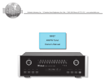
AM/FM Tuner
MR85
Owner’s Manual
McIntosh Laboratory, Inc. 2 Chambers Street Binghamton, New York 13903-2699 Phone: 607-723-3512 FAX: 607-724-0549
The lightning flash with arrowhead,
within an equilateral triangle, is intended
to alert the user to the presence of
uninsulated “dangerous voltage” within
the product’s enclosure that may be of
sufficient magnitude to constitute a risk
of electric shock to persons.
WARNING - TO REDUCE RISK OF
FIRE OR ELECTRICAL SHOCK, DO
NOT EXPOSE THIS EQUIPMENT TO
RAIN OR MOISTURE.
IMPORTANT SAFETY
INSTRUCTIONS!
PLEASE READ THEM BEFORE
OPERATING THIS EQUIPMENT.
1. Read these instructions.
2. Keep these instructions.
3. Heed all warnings.
4. Follow all instructions.
5. Do not use this apparatus near water.
6. Clean only with a dry cloth.
7. Do not block any ventilation openings. Install in
accordance with the manufacturer’s instructions.
8. Do not install near any heat sources such as
radiators, heat registers, stoves, or other
apparatus (including amplifiers) that produce
heat.
9. Do not defeat the safety purpose of the polarized
or grounding-type plug. A polarized plug has two
blades with one wider than the other. A grounding
type plug has two blades and a third grounding
prong. The wide blade or the third prong are
provided for your safety. If the provided plug
does not fit into your outlet, consult an electrician
for replacement of the obsolete outlet.
10. Protect the power cord from being walked on or
pinched particularly at plugs, convenience
receptacles, and the point where they exit from
the apparatus.
2
The exclamation point within an equilateral triangle is intended to alert the
user to the presence of important
operating and maintenance (servicing) instructions in the literature accompanying the appliance.
NO USER-SERVICEABLE PARTS
INSIDE. REFER SERVICING TO
QUALIFIED PERSONNEL.
To prevent the risk of electric shock, do not remove cover or
back. No user-serviceable parts inside.
11. Only use attachments/accessories specified by the
manufacturer.
12. Use only with the cart, stand, tripod, bracket, or
table specified by the manufacturer,
or sold with the apparatus. When a
cart is used, use caution when moving
the cart/apparatus combination to
avoid injury from tip-over.
13. Unplug this apparatus during lightning storms or
when unused for long periods of time.
14. Refer all servicing to qualified service personnel.
Servicing is required when the apparatus has
been damaged in any way, such as power-supply
cord or plug is damaged, liquid has been spilled
or objects have fallen into the apparatus, the
apparatus has been exposed to rain or moisture,
does not operate normally, or has been dropped.
15. Do not expose this equipment to dripping or
splashing and ensure that no objects filled with
liquids, such as vases, are placed on the
equipment.
16. To completely disconnect this equipment from
the a.c. mains, disconnect the power supply cord
plug from the a.c. receptacle.
17. The mains plug of the power supply cord shall
remain readily operable.
Safety Instructions
Outdoor Antenna Grounding
If an outside antenna or cable system is connected to
the product, be sure the antenna or cable system is
grounded so as to provide some protection against
voltage surges and built-up static charge. Article 810
of the National Electrical Code, ANSI/NFPA 70, provides information with reguards to proper grounding
of the mast and supporting structure, grounding of the
lead-in wire to an antenna discharge unit, and size of
ground conductors, location of antenna-discharge unit,
connection to ground electrodes and requirements for
the grounding electrode.
Example of antenna grounding as per
National Electrical Code, ANSI/NFPA 70
3
Thank You
Table of Contents
Your decision to own this McIntosh MR85 AM/FM Tuner
ranks you at the very top among discriminating music listeners. You now have “The Best.” The McIntosh dedication
to “Quality,” is assurance that you will receive many years
of musical enjoyment from this unit.
Please take a short time to read the information in this
manual. We want you to be as familiar as possible with all
the features and functions of your new McIntosh.
Safety Instructions ............................................................ 2
Thank You and Please Take a Moment ............................. 2
Technical Assistance and Customer Service .................... 2
Table of Contents and Important Information .................. 2
Connector Information ..................................................... 5
Introduction and Performance Features ............................ 5
Dimensions ....................................................................... 6
Installation ........................................................................ 7
MR85 Rear Panel and RAA1 Top Panel Connections ..... 8
How to Connect ................................................................ 9
How to Connect with Optional Tuner Module ............... 10
Front Panel Controls, Displays,
Push-Buttons and Switch ................................................ 11
How to Operate ............................................................... 12
How to Assign Preset Stations and Custom Names ....... 14
Preset Station Lists ......................................................... 16
Information about the Optional TM1 Tuner Module ...... 17
Specifications ................................................................. 18
Packing Instruction ......................................................... 19
Please Take A Moment
The serial number, purchase date and McIntosh Dealer
name are important to you for possible insurance claim or
future service. The spaces below have been provided for
you to record that information:
Serial Number:
Purchase Date:
Dealer Name:
Technical Assistance
If at any time you have questions about your McIntosh
product, contact your McIntosh Dealer who is familiar with
your McIntosh equipment and any other brands that may
be part of your system. If you or your Dealer wish additional help concerning a suspected problem, you can receive technical assistance for all McIntosh products at:
McIntosh Laboratory, Inc.
2 Chambers Street
Binghamton, New York 13903
Phone: 607-723-1545
Fax: 607-723-3636
Customer Service
If it is determined that your McIntosh product is in need of
repair, you can return it to your Dealer. You can also return
it to the McIntosh Laboratory Service Department. For assistance on factory repair return procedure, contact the
McIntosh Service Department at:
McIntosh Laboratory, Inc.
2 Chambers Street
Binghamton, New York 13903
Phone: 607-723-3515
Fax: 607-723-1917
Copyright 2001, 2004 © by McIntosh Laboratory, Inc.
4
Important Information
1. The following Connecting Cable is available from the
McIntosh Parts Department:
Data and Power Control Cable Part No. 170-202
Six foot, 2 conductor shielded, with two 1/8 inch stereo
mini phone plugs.
RAA1 AM Antenna Connecting Cable Part No. 171-371
Thirty foot, 2 conductor shielded, with 7 pin DIN Plug
and 5 pin Terminal Plug.
2. For additional connection information, refer to the owner’s
manual(s) for any component(s) connected to the MR85.
3. The MR85 Tuner has the provision for adding an optional
second TM1 Tuner Module and is available from your
McIntosh Dealer. With the addition of this second tuner
module, you can be listening to two different radio stations
simultaneously. This allows for such capabilities as listening
to one station while recording a different station or listening
to one station, while another station is being listened to in a
second room.
4. Several different types of FM antennas or cable reception can
be used with the MR85.
A. A flexible indoor dipole antenna makes a convenient
antenna for high signal strength areas and may be
effective in buildings without metal siding or insulation.
B. An existing outdoor directional VHF-TV/FM or FM
Antenna with a rotor can be connected and will provide
the best reception. Consult your McIntosh Dealer for
assistance.
C. A signal from your local cable company can also be
connected. Consult your cable company for installation
assistance.
5. FM Antenna connections to the MR85 require either RG6 or
RG59U coaxial cable.
Introduction and Performance Features
Connector Information
RAA1 Connector
Connect the shield and two leads of a shielded 2 conductor
cable to the supplied 5 Pin Terminal Connector Plug. Refer
to the connection information on the top cover of the
RAA1.
Black
Red
Green
5 PinTerminal Connector
1. N/C
4. Black Wire
2. N/C
5. Green Wire (Shield)
3. Red Wire
A newly designed, optically encoded weighted flywheel
system makes ‘dialing in’ stations a breeze. Reminiscent of
the dial-cord flywheel tuning method found in classic
McIntosh Tuners. The MR85 automatically mutes when
manually tuning between stations, yet provides the ability
to be switched off when searching for very weak stations.
Spatial Sound Enhancement
An automatic variable stereo separation control circuit is
used to reduce background noise when receiving weak stereo stations. A sound Spatializer circuit can be selected for
Tuner 1 Enhancement. This circuit can expand the sound
field for FM stations with poor separation; it also provides
a pseudo-stereo effect for AM stations.
Positive
N/C
Negative
Data Connectors
The MR85’s Data Port Output provides Remote Control Signals. Use Data Signal
a 1/8 inch stereo mini phone plug
N/C
to connect to the Data Port Inputs
Ground
on McIntosh A/V Control Centers.
Introduction
The MR85 AM/FM Tuner is an elegant instrument that allows you to enjoy outstanding music reproduction. It includes a wide range of convenient operating functions to
enhance your listening experience. The classic McIntosh
MR85 will perfectly compliment a McIntosh System of
incomparable performance and style.
Performance Features
•
Special FM RF Amplifier
Double-Diffused Metal Oxide Field Effect Transistor
(DMOS-FET) RF amplifier increases sensitivity and Cross
Modulation rejection.
•
• Flywheel Manual Tuning and Automute
• FM Stereo Auto Blend Circuitry and
7 Pin DIN Connector
1. Red Wire
5. N/C
2. Black Wire 6. Jumper from Pin 7
3. N/C
7. Green Wire (Shield)
4. N/C
and Jumper to Pin 6
Power Control Connectors
The MR85’s Power Control Output
provides a 5 volt signal. Use a 1/8
inch stereo mini phone plug to connect to the Power Control Output on
other McIntosh Components.
assuring the best possible reception.
External AM RF Amplifier and Antenna
The included RAA1 Remote AM Antenna contains an electrostatically shielded AM RF Amplifier Stage and can be
located in a remote area away from sources of interference
•
Optional Second Tuner Module
The McIntosh TM1 Tuner Module may be added to the
MR85 by your Dealer and is the most economical way to
add a second tuner to a system. This is ideal for applications where two tuners may be used at the same time, such
as Multizone Systems or listening to one station while recording another station.
•
Preset Stations and Custom Preset Naming
Nine AM and nine FM station presets with custom naming
(any desired name may contain up to eight characters) for
each tuner module make it easy to listen to your favorite
stations. For example, FM Preset Number 3 (92.50MHz)
can be renamed “JAZZ 7”, or “WXYZ”. The station presets, custom naming and functions modes are retained in
Permanent Memory even when AC power is turned off.
•
Alphanumeric Fluorescent Display
The Multifunction Front Panel Display indicates station
frequency, station preset number, custom naming, signal
strength, stereo and broadcast band. The display intensity is
fully adjustable.
• Adjustable Output Level and Remote Control
Capable
Both Tuner 1 and the optional Tuner 2 have Variable Outputs which can be used to match audio levels between various sources. When used in conjunction with a McIntosh
Control Center or Multizone Controller, tuning functions
can be performed with a remote control.
5
Dimensions
MR85 Dimensions
The following dimensions can assist in determining the
best location for your MR85. There is additional information on the next page pertaining to installing the MR85 into
cabinets.
17-1/2"
44.45cm
5 -3/8"
13.69cm
Front View of the MR85
6"
15.24cm
17"
43.18cm
4 -5/8"
11.75cm
Rear View of the MR85
13 -1/4"
33.65cm
18-3/8"
46.67cm
5/8"
1.59cm
17"
43.18cm
3/16"
0.48cm
Side View of the MR85
4-13/16"
12.22cm
13/16"
2.06cm
14"
35.56cm
6
1"
2.54cm
Installation
Installation
The MR85 can be placed upright on a table or shelf, standing on its four feet. It also can be custom installed in a
piece of furniture or cabinet of your choice. The four feet
may be removed from the bottom of the MR85 when it is
custom installed as outlined below. The four feet together
with the mounting screws should be retained for possible
future use if the MR85 is removed from the custom installation and used free standing. The required panel cutout,
ventilation cutout and unit dimensions are shown.
Always provide adequate ventilation for your MR85.
Cool operation
ensures the longest possible operating life for any
electronic instrument. Do not install the MR85
MR85 Front Panel
directly above a
Custom Cabinet Cutout
heat generating
component such
as a high powered
amplifier. If all the
components are
installed in a
single cabinet, a
quiet running ventilation fan can be
Cabinet
a definite asset in
Front
Panel
maintaining all the
system components at the
coolest possible
MR85 Side View
operating temin Custom Cabinet
perature.
A custom cabinet installation
should provide the
Support
Shelf
following minimum spacing dimensions for cool
operation. Allow
at least 2 inches
17/32"
(5.08 cm) above
MR85
Bottom
View
1.35cm
the top, 2 inches
in
Custom
Cabinet
(5.08cm) below
the bottom and
1 inch (2.54 cm) on each side of the AM/FM Tuner, so that
airflow is not obstructed. Allow 20 inches (50.8 cm) depth
behind the front panel. Allow 1 inch (2.54 cm) in front of
the mounting panel for knob clearance. Be sure to cut out a
ventilation hole in the mounting shelf according to the dimensions in the drawing.
17-1/16"
43.34cm
4 -7/8"
12.38cm
Cutout Opening for Custom Mounting
Cutout Opening for Ventilation
Chassis
Spacers
1"
2.54cm
14"
35.56cm
14"
35.56cm
Cutout Opening
for Ventilation
15-1/16"
38.26cm
7
MR85 Rear Panel and RAA1 Top Panel Connections
ANTENNA 1
RAA1 AM ANT
connector for the
supplied McIntosh
Remote AM Antenna
TUNER 1 VARIABLE
OUTPUTS supply audio
signals that can be adjusted
by the rear panel TUNER 1
OUTPUT LEVEL control
ANTENNA 1
75Ω (ohm) FM
ANT connects to
an external FM
antenna or cable
TUNER 1 OUTPUT
LEVEL control adjusts
the volume level of the
Variable Outputs
EXT TUNER connects to
the MR85 Tuner RAA1
ANTenna 1 Input
8
TUNER 2 OUTPUT
LEVEL control reserved for the optional TM1 second
tuner module
POWER CONTROL IN
jack accepts a turn on signal from a McIntosh Control Center. The OUT jack
sends the turn on signal to
another McIntosh product
TUNER 1 DATA IN
jack receives tuner
control and operating
data from a McIntosh
Control Center to
control the Tuner 1
Module
TUNER 1 FIXED
OUTPUTS supply
audio signals at a
volume level that
cannot be changed
Spaces reserved for
the optional TM1
second tuner module
TUNER 2 DATA
IN jack reserved
for the optional
TM1 second tuner
module
Connect the MR85 power cord
to a live AC outlet. Refer to
information on the back panel
of the MR85 to determine the
correct voltage
TUNER 2 FIXED and
VARIABLE OUTPUTS
jacks reserved for the
optional TM1 second
tuner module
How to Connect
How to Connect
1. Connect a data cable from the TUNER 1 DATA IN jack
to the TUNER DATA PORT of a McIntosh Control
Center or Preamplifier.
Note: Remote Control operation of the Tuner is made
possible with a Data Cable connected between the
MR85 and a McIntosh Control Center or
Preamplifier. If the MR85 Tuner is connected to a
non-McIntosh Preamplifier, remote control
operation is still possible with an appropriate
interface and McIntosh Remote Control. Contact
your McIntosh Dealer for additional details.
2. Connect a power control cable from the POWER CONTROL IN jack to the POWER CONTROL OUT or
ACC jack of a McIntosh Preamplifier, Control Center
or other McIntosh component.
3. Connect an audio cable from the TUNER 1 FIXED
OUTPUTS to the TUNER INPUTS of a preamplifier
or control center.
Note: An optional connection would be to use the TUNER 1
VARIABLE OUTPUTS.
4. Connect the FM Antenna or Cable (from the Cable
Company) to the MR85 Tuner 75Ω (Ohm) FM
ANTenna connector.
5. Connect with the supplied cable, from the 5 Pin Socket
of the McIntosh RAA1 Remote AM Antenna to the
MR85 Tuner RAA1 AM ANTenna DIN Socket.
6. Plug the MR85 AC Power Cord into an AC Outlet.
McIntosh Control Center
To AC Outlet
9
How to Connect with Optional Tuner Module
How to Connect with Optional Tuner Module
1. Connect a data cable from the TUNER 1 DATA IN jack
to the TUNER DATA PORT of a McIntosh Multizone
Control Center.
Note: Remote Control operation of the Tuner is made
possible with a Data Cables connected between the
MR85 and a McIntosh Control Center or
Preamplifier. If the MR85 Tuner is connected to a
non-McIntosh Preamplifier, remote control
operation is still possible with an appropriate
interface and McIntosh Remote Control. Contact
your McIntosh Dealer for additional details.
2. Connect a data cable from the TUNER 2 DATA IN jack
to the LOCAL ZONE 1 AUX IN DATA PORT of a
McIntosh Multizone Controller.
3. Connect a power control cable from the POWER CONTROL IN jack to the POWER CONTROL OUT of a
McIntosh Multizone Controller.
4. Connect an audio cable from
the TUNER 1 FIXED OUTPUTS to the TUNER INPUTS
of a McIntosh Multizone Control Center.
AUX IN AUDIO Jacks of a McIntosh Multizone Controller.
Note: An optional connection would be to use the TUNER
2 VARIABLE OUTPUTS.
6. Connect the FM Antenna(s) or Cable (from the Cable
Company) to the MR85 Tuner 75Ω (Ohm) FM
ANTenna connector for both Tuner 1 and 2.
Note: If the same FM Antenna or Cable (from the Cable
Company) is used for both Tuner 1 and 2, a suitable
coaxial splitter must be utilized.
7. Connect with the supplied cables, from the 5 Pin Socket
of the McIntosh RAA1 Remote AM Antenna to the
MR85 Tuner RAA1 AM ANTenna DIN Sockets for
both Tuner 1 and 2.
8. Plug the MR85 AC Power Cord into an AC Outlet.
Note: An optional connection
would be to use the
TUNER 1 VARIABLE
OUTPUTS.
5. Connect an audio cable from
the TUNER 2 FIXED OUTPUTS to the LOCAL ZONE 1
To AC Outlet
10
McIntosh Multizone Controller
Front Panel Controls, Displays, Push-Buttons and Switch
Enters desired radio
stations and custom
names into memory
Indicates the
Broadcast Band of
the Radio Station
Indicates the Preset
Memory Location
Selects Preset
Stations, is used
for custom station naming and
display brightness
Selects front panel
display brightness and
display cursor position during custom
station naming
Adds Spatial Audio
Enhancement to the
received sound
Indicates the Radio
Station Frequency
Selects the
Mono Mode
of operation
Indicates reception of
a FM Stereo Signal
Tuning Knob for
manual tuning of
radio stations
Indicates the
relative Signal
Strength of the
radio station
signal
Select AM or
FM tuning
bands
Selects which tuner
module is controllable
from the front panel
and displayed
Turns all
AC Power
On or Off
Selects the
Automute Function
which mutes the
audio between radio stations when
manually tuning
Automatically tunes
up or down the AM
or FM broadcast
band
Turns the
MR85 On
and Off
11
How to Operate
Power On
Press the POWER switch to ON. The Red LED, above the
STANDBY/ON Push-button, lights to indicate the MR85 is
in Standby Mode. To turn ON the MR85 press the
STANDBY/ON push-button. Refer to figure 1.
Note: The POWER Switch is only intended to be switched
OFF when the MR85 Tuner is not used for extended
periods of time, like while away on vacation. During
normal operation, the POWER Switch should stay in the
ON position. Press the STANDBY/ON Push-button for
turning the MR85 ON and OFF. When the Power
Control Cable is connected to a McIntosh Control
Center, A/V Multizone System Controller or
Preamplifier, the MR85 Tuner will automatically switch
ON and OFF.
The McIntosh MR85 is an advanced design AM/FM Tuner
with many desirable performance features to enhance your
enjoyment of radio broadcasts. There are three modes of
tuning to an AM/FM Broadcast Station. There is Manual
Tuning using the TUNING Knob; Seek Mode Station Selection using the SEEK S (Up) and T (Down) Pushbutton(s); and Preset Station Selection using the PRESET
Selection Knob.
Note: When the MR85 AM/FM Tuner is connected to a
McIntosh Control Center, A/V Multizone System
Controller or Preamplifier via a data connection ,the
tuner functions such as SEEK, direct PRESET Selection
and REVIEW of Preset Stations may be controlled by
the McIntosh Remote Control and/or Keypad.
Preset Selector Switch
The PRESET Selection Switch allows selection of desired
radio stations that have already been stored into memory.
There are up to 9 AM and 9 FM stations that can be stored
for the Tuner 1. The optional secondary Tuner 2 Module
also has up to 9 AM and 9 FM stations that can be stored
into memory. The PRESET Selection Switch also assists in
changing the Front Panel Alphanumeric Display from indicating the Station Frequency (default), to displaying personalized names of your choice. Example, instead of the
Front Panel Display showing Preset number 3 as “105.70
FM” it could display “JAZZ 7”. Refer to “How to Assign
Presets Stations and Custom Names” for further information.
Note: The PRESET Selection Switch will not access Station
Presets that have been left blank. If no Presets have
been assigned, the Front Panel Display will show “NO
PRESETS” until at least one station has been entered
into memory. Refer to figure 2 below.
Figure 2
Manual Tuning
Manual Tuning is provided through the Front Panel TUNING Knob. Rotate the TUNING Knob clockwise to tune up
in frequency, 10kHz steps for AM or 200kHz steps for FM.
Spin the knob to tune up continuously. Rotate the TUNING
Knob counterclockwise in the same manner to tune down
in frequency. When a station is selected, the Front Panel
Display will indicate (from left to right) a Preset Number,
if that station has been assigned a Preset, the FM Station
Frequency, the received Stations Signal Strength from 1 to
9, and a dot (located to the right of the Signal Strength
Digit) if the station is broadcasting stereo.
Figure 1
12
Note: FM band indications are in Megahertz. In the US and
Canada, they change frequency in 200kHz steps. The
second digit to the right of the dot which displays a 0, is
used for FM stations in Europe where stations change
in 50kHz steps. In Europe and Japan, the AM display
changes in 9kHz steps.
How to Operate
Enter Mode
The ENTER Push-button is used to enter into memory, desired AM or FM radio stations and any custom naming you
might wish. A station Preset and its custom name may also
be cleared from memory using the ENTER Push-button.
The LED above the ENTER Push-button will light when in
the Preset Enter Mode.
Display Modes
Press the DISPLAY Push-button and rotate the PRESET
Knob to adjust the Front Panel Alphanumeric Display
Brightness from 0 (Off) to 31 (Bright), refer to figure 3.
Figure 3
Note: For Custom Naming Station Presets with the name of
your choice refer to page 15.
Spatial Enhancement
Press the Spatial push-button to add Audio Enhancement to
either an AM or FM signal. For example, AM Stations with
monaural signals will have a simulated stereo effect. The
LED above the SPATIAL Push-button will light when in
the Spatial Mode.
Note: The Spatial Enhancement function is for the Tuner 1
only.
Mono Mode
Press the MONO Push-button to combine left and right stereo signals to monaural. This is useful when the MR85
Tuner is receiving a very weak Stereo Signal that might be
accompanied with a high degree of background noise. By
switching to MONO Mode, most of the background noise
will disappear, thus making the station more listenable. The
LED above the MONO Push-button will light when in the
MONO Mode.
Note: When the tuned to an AM Radio Station the tuner will
automatically switch to the MONO Mode.
Tuner Selector
The Tuner Selector selects between the default Tuner 1 and
the optional secondary Tuner 2 Module, if installed. Once
the desired tuner is selected, the Front Panel Controls including Station Selection and Preset Assignment may be
performed. The Number 1 LED above the TUNER Pushbutton will light, indicating when Tuner 1 has been selected and the Number 2 LED above the TUNER Push-button will light when Tuner 2 Module is selected.
Note: If the optional secondary Tuner 2 Module is not
installed, the TUNER Selector will stay on the TUNER 1
selection.
AM/FM Band Selector
Select the AM or FM Broadcast Band by pressing the AM/
FM push-button.
Note: When the Front Panel Alphanumeric Display is
displaying the radio station frequency (default), the
letters AM or FM will appear to the right of the tuned
stations frequency to indicate the broadcast band.
SEEK S and T
Press and release the Front Panel SEEK S (Up) and T
(Down) Push-button(s), to move from one station to the
next. Press and hold the SEEK Push-button to move
continuously up or down the broadcast band.
Automute Function
When manually tuning through the band, the outputs will
unmute only when a strong radio station is sensed and received. Sometimes it is desirable to search for a very weak
station and the AUTOMUTE Function can be switched
OFF. This will allow all stations to be heard as well as
noise and interference normally found in-between stations.
The LED above the AUTOMUTE Push-button will light
when the Automute Function is active.
Note: The AUTOMUTE Function can only be switched OFF
when manually tuning to a station using the TUNING
Knob. When using SEEK S (Up) and T (Down) Pushbutton(s), the AUTOMUTE Function will always be
engaged.
Output Level Control (Rear Panel)
There are both FIXED OUTPUTS and VARIABLE OUTPUTS on the MR85 Rear Panel for Tuner 1 and optional
secondary Tuner 2 Module. For most applications, the volume level at the FIXED OUTPUTS will match other
sources connected to the McIntosh Control Center or
Preamplifier. If the volume level from the tuner is higher
than from other sources, the VARIABLE OUTPUTS together with the OUTPUT LEVEL Control may be used to
reduce the tuner volume level.
Reset of Microprocessor
In the event that the controls of the MR85 stop functioning,
there is a built-in user reset function. Press the POWER
switch to the OFF position and wait for two minutes. Then
press the POWER switch to ON; the Red LED above the
STANDBY/ON Push-button, lights to indicate the MR85 is
13
in Standby Mode. To turn ON the MR85, press the
STANDBY/ON Push-button.
Note: The above condition is usually caused by either
interruptions or changes in AC voltage.
How to Assign Preset Stations
The MR85 AM/FM Tuner allows for presetting your favorite radio stations into memory. It will also remember any
desired audio modes of operation such as Stereo/Mono and
Spatial Enhancement for each station separately. To enter
Presets and Audio Modes follow the below steps:
Note: The MR85 Tuner 1 and the optional secondary Tuner 2
Module each can store up to 9 AM and 9 FM stations.
1. Select the AM or FM broadcast band.
2. Tune to the desired radio station with either the Front
Panel TUNING Knob or the SEEK S (Up) and T
(Down) Push-button(s).
3. Optionally, select the Mono and/or Spatial Enhancement Modes of Operation for that station.
Note: The Spatial Enhancement Mode is only applicable
to the Tuner 1. All AM Radio Stations are
automatically received in Mono.
4. Momentarily press and release the Front Panel ENTER
push-button. The LED above the ENTER push-button
will light and the Front Panel Display will indicate 1
AVAILABLE, which is the first of 9 Preset Numbers
that can be assigned. Refer to figure 4.
Figure 5
7. To verify the Station Preset(s) you have just entered,
rotate the PRESET Knob clockwise or counterclockwise to cycle through and confirm your preset assignments.
How To Clear an Assigned Station Preset
1. Press and release the ENTER Push-button; the LED
above the ENTER Push-button will light.
2. Rotate the PRESET Knob clockwise or counterclockwise to select the desired Station Preset you wish to
clear.
3. Press and Hold the ENTER Push-button for approximately 3 seconds until the Front Panel Display indicates the word CLEARED. Refer to figure 6.
Figure 6
Note: If you wish to replace an already assigned Station
Preset with another radio station, it is not
necessary to clear the Preset first, just enter in the
new station for that Preset. The new station will
automatically replace the previously assigned
station.
4. To clear any additional Station Presets perform steps 1
through 3 again.
Figure 4
Note: Presets are automatically assigned in order from 1
to 9.
5. Press and release the front panel ENTER push-button a
second time to store the Preset into memory, the LED
above the ENTER push-button will turn off and that
station Preset Selection will be assigned Preset Number 1. The assigned Preset Number will appear on the
Front Panel Display to the right of the Station Frequency whenever it is selected. Refer to figure 5.
6. Assign additional station Presets by performing steps 1
through 5 until a total of 9 AM and 9 FM Station Presets have been assigned. Each time you assign an additional Preset Number, the Front Panel Display will indicate the number of the next available preset.
Note: If all 9 presets are assigned and you press ENTER,
the display will indicate the station selected for
preset number 1.
14
How to Assign Custom Names
The Front Panel Alphanumeric Display of the MR85 together with the built in memory, allows for Custom Naming of each Station Preset. Instead of the Front Panel just
indicating the frequency of the received radio station, it
could indicate such things as type of music played on that
station. The assignable characters include the alphabet,
numbers, and symbols. To enter Custom Presets Names
follow the below steps:
Note: In the below example, we will Custom Name an already
assigned FM Station Preset Number 1 which has a
frequency of 99.10MHz and rename it JAZZ 7. The
Custom Naming of a Station is applicable for both
Tuner 1 and the optional secondary Tuner 2 Module.
1. Momentarily press and release the Front Panel ENTER
How to Assign Preset Stations and Custom Names
push-button. The LED above the ENTER push-button
will light.
2. Select Station Preset Number 1, by rotating the PRESET Knob clockwise or counterclockwise.
3. Push the DISPLAY Push-button and the Front Panel
Display of the Station Frequency (default) will be replaced by “1”, a blank space, and then a flashing “A”.
Refer to figure 7.
10. Rotate the PRESET Knob clockwise again until
the “A” appears to the right of the “JAZZ”.
11. Rotate the TUNING Knob clockwise to scroll
through the alphabet until no character appears.
12. Rotate the PRESET Knob clockwise again until
the “A” appears to the right of the “JAZZ ”.
13. Rotate the TUNING Knob clockwise to scroll
through the alphabet and numbers until the “7”
digit appears. Refer to figure 12.
Figure 7
Note: The number 1 is the assigned Preset Number
followed by the first of eight possible characters of
the new Assigned Preset Name.
4. Rotate the TUNING Knob clockwise to scroll through
the alphabet until the character “J” appears. Refer to
figure 8.
Figure 8
5. Rotate the PRESET Knob clockwise until the “A” appears to the right of the “J”. Refer to figure 9.
Figure 12
14. Press and release the front panel ENTER push-button a second time to store the newly assigned Preset Name into memory; the LED above the ENTER push-button will turn Off and the assigned
Preset Name will appear on the Front Panel Display.
Note: If a Preset has been Custom Named, it is
possible to restore the default Station
Frequency Display if desired. Press the ENTER
Push-button once, then press and hold the
DISPLAY Push-button for 3 seconds.
Figure 9
6. Rotate the PRESET Knob clockwise again until the
“A” appears to the right of the “JA”.
7. Rotate the TUNING Knob clockwise to scroll through
the alphabet until the character “Z” appears. Refer to
figure 10.
Figure 10
8. Rotate the PRESET Knob clockwise again until the
“A” appears to the right of the “JAZ”.
9. Repeat step 7 and refer to figure 11.
Figure 11
15
Preset Station Lists
Preset
No.
Tuner 1 Preset Stations
Tuner 2 (Optional Module) Preset Stations
AM Station Presets
AM Station Presets
Frequency
Call
Letters
Name
Preset
No.
1
1
2
2
3
3
4
4
5
5
6
6
7
7
8
8
9
9
FM Station Presets
Preset
No.
16
Frequency
Call
Letters
Frequency
Call
Letters
Name
FM Station Presets
Name
Preset
No.
1
1
2
2
3
3
4
4
5
5
6
6
7
7
8
8
9
9
Frequency
Call
Letters
Name
Information about the Optional TM1 Tuner Module
Cable for connection of the RAA1
to the MR85 AM Antenna 2 Jack
McIntosh RAA1 Remote
AM Antenna
Hook-up cables for the McIntosh
TM1 AM/FM Tuner Module
High Performance McIntosh
AM/FM Tuner Module
Benefits of Adding the Second McIntosh AM/FM TM1 Tuner Module
z Adds the functionality of a second McIntosh Quality Tuner to your MR85 for
a modest additional investment.
z Listen to one Radio Station while recording another.
z Add Multiroom enjoyment, listen to two different Radio Stations in different
rooms of your home simultaneously.
z Your McIntosh Dealer can install the Second TM1 Tuner Module into your
MR85 for you at any time, usually while you wait.
17
Specifications
FM Tuner Specifications
AM Tuner Specifications
Useable Sensitivity
14dBF which is 1.4uV across 75 ohms
Sensitivity
20uV External Antenna Input
50dB Quieting Sensitivity
Mono: 19dBF which is 2.4uV across 75 ohms
Stereo: 35dBF which is 15uV across 75 ohms
Signal To Noise Ratio
48dB at 30% modulation
58dB at 100% modulation
Signal To Noise Ratio
Mono: 75dB
Stereo: 70dB
Harmonic Distortion
0.5% maximum at 50% modulation
Frequency Response
Mono: + 0, - 1dB from 20 to 15,000Hz
Stereo: + 0, - 1dB from 20 to 15,000Hz
Harmonic Distortion
Mono: 0.3% at 100Hz
0.3% at 1,000Hz
0.3% at 10,000Hz
Stereo: 0.45% at 100Hz
0.45% at 1,000Hz
0.65% at 10,000Hz
Frequency Response
50Hz to 6kHz NRSC
Adjacent Channel Selectivity
45dB minimum IHF
Image Rejection
65dB minimum from 540kHz to 1600kHz
IF Rejection
80dB minimum
General Specifications
Intermodulation Distortion
Mono: 0.25%
Stereo: 0.45%
Rated Output
Fixed output: 1.2 Volts
Variable output: 0 - 1.2 Volts
Capture Ratio
1.2dB
Output Impedance
Alternate Channel Selectivity
75dB
Power Requirements
100 Volts, 50/60Hz at 20 watts
110 Volts, 50/60Hz at 20 watts
120 Volts, 50/60Hz at 20 watts
220 Volts, 50/60Hz at 20 watts
230 Volts, 50/60Hz at 20 watts
240 Volts, 50/60Hz at 20 watts
Spurious Response
100dB
Image Response
75dB
RF Intermodulation
65dB
Stereo Separation
45dB at
100Hz
45dB at 1,000Hz
35dB at 10,000Hz
SCA Rejection
65dB
18
Less than 100 ohms
Note: Refer to the rear panel of the MR85 for the correct
voltage.
Overall Dimensions
Width is 17-1/2 inches (44.5cm)
Height is 6 inches(15.3cm) including feet
Depth is 19 inches (48.3cm) including Front Panel and
Knob
Weight
25.5 pounds (11.6 Kg) net, 43 pounds (19.5 Kg) in shipping carton
Packing Instructions
Packing Instructions
In the event it is necessary to repack the equipment for
shipment, the equipment must be packed exactly as shown
below. It is very important that the four plastic feet are attached to the bottom of the equipment. This will ensure the
proper equipment location on the bottom pad. Failure to do
this will result in shipping damage.
Use the original shipping carton and interior parts only
if they are all in good serviceable condition. If a shipping
carton or any of the interior part(s) are needed, please call
or write Customer Service Repair Department of McIntosh
Laboratory. Please see the Parts List for the correct part
numbers.
Quantity
1
2
2
1
Part Number
034125
033837
034126
034044
Description
Shipping carton only
End Cap
End Cap
Corrugated Wrap
1
1
1
1
033836
033725
034008
034037
Inside carton only
Top Pad
Bottom pad
Inner carton pad
4
4
4
017218
100159
104083
Plastic foot
#10-32 x 3/4” Machine screw
#10 x 7/16” Flat washer
1
049259
Shipping carton complete with
all the above parts
19
McIntosh Laboratory, Inc.
2 Chambers Street
Binghamton, NY 13903
The continuous improvement of its products is
the policy of McIntosh Laboratory Incorporated
who reserve the right to improve design without
notice.
Printed in the U.S.A.
McIntosh Part No. 04069802