1
Mazda3
Owner's Manual
Form No. 8S18-EA-03I (Part No. 9999-95-038C-04)
2004
8S18
2004
Mazda3
Owner's Manual
J48C_8S18-EA-03I_Edition1.book Page 1 Wednesday, August 6, 2003 8:51 AM
Form No. 8S18-EA-03I
J48C_8S18-EA-03I_Edition1.book Page 2 Wednesday, August 6, 2003 8:51 AM
J48C_8S18-EA-03I_Edition1.book Page 3 Wednesday, August 6, 2003 8:51 AM
A Word to Mazda Owners
Thank you for choosing a Mazda. We at Mazda design and build vehicles with complete
customer satisfaction in mind.
To help ensure enjoyable and trouble-free operation of your Mazda, read this manual
carefully and follow its recommendations.
An Authorized Mazda Dealer knows your vehicle best. So when maintenance or service is
necessary, that’s the place to go.
Our nationwide network of Mazda professionals is dedicated to providing you with the best
possible service.
We assure you that all of us at Mazda have an ongoing interest in your motoring pleasure
and in your full satisfaction with your Mazda product.
Mazda Motor Corporation
HIROSHIMA, JAPAN
Important Notes About This Manual
Keep this manual in the glove box as a handy reference for the safe and enjoyable use of your Mazda. Should
you resell the vehicle, leave this manual with it for the next owner.
All specifications and descriptions are accurate at the time of printing. Because improvement is a constant goal
at Mazda, we reserve the right to make changes in specifications at any time without notice and without
obligation.
Air Conditioning and the Environment
Your Mazda’s genuine air conditioner is filled with HFC134a (R134a), a refrigerant that has been found not to
damage the earth’s ozone layer. If the air conditioner does not operate properly, consult an Authorized Mazda
Dealer.
Please be aware that this manual applies to all models, equipment and options. As a result, you may find
some explanations for equipment not installed on your vehicle.
©2003 Mazda Motor Corporation
Printed in Japan Sep. 2003(Print1)
Form No. 8S18-EA-03I
J48C_8S18-EA-03I_Edition1.book Page 4 Wednesday, August 6, 2003 8:51 AM
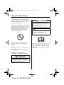
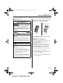
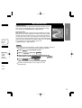
How to Use This Manual
We want to help you get the most driving
pleasure from your vehicle. Your owner’s
manual, when read from cover to cover,
can do that in many ways.
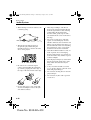
Illustrations complement the words of the
manual to best explain how to enjoy your
Mazda. By reading your manual, you can
find out about the features, important
safety information, and driving under
various road conditions.
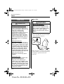
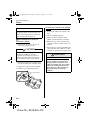
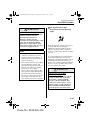
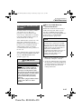
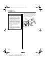
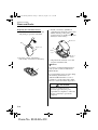
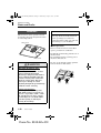
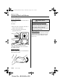
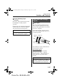
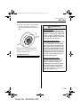
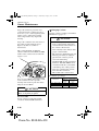
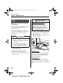
The above symbol in this manual means
"Do not do this " or "Do not let this
happen".
Index: A good place to start is the Index,
an alphabetical listing of all information
in your manual.
You’ll find several WARNINGs,
CAUTIONs, and NOTEs in the manual.
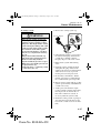
WARNING
A WARNING indicates a situation in
which serious injury or death could
result if the warning is ignored.
Form No. 8S18-EA-03I
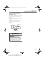
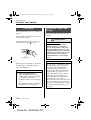
CAUTION
A CAUTION indicates a situation in
which bodily injury or damage to your
vehicle, or both, could result if the
caution is ignored.
NOTE
A NOTE provides information and
sometimes suggests how to make
better use of your vehicle.
The above symbol, located on some parts
of the vehicle, indicates that this manual
contains information related to the part.
Please refer to the manual for a detailed
explanation.
J48C_8S18-EA-03I_Edition1.book Page 5 Wednesday, August 6, 2003 8:51 AM
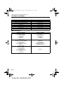
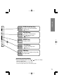
Table of Contents
Your Vehicle at a Glance
Interior, exterior views and part identification of your Mazda.
Essential Safety Equipment
Use of safety equipment, including seats, seat belt system, SRS air bags and
child-restraint systems.
Knowing Your Mazda
Explanation of basic operations and controls; opening/closing and adjustment
of various parts.
Before Driving Your Mazda
Important information about driving your Mazda.
Driving Your Mazda
Explanation of instruments and controls.
Interior Comfort
Use of various features for drive comfort, including climate control and audio
system.
In Case of an Emergency
Helpful information on what to do in an emergency.
Maintenance and Care
How to keep your Mazda in top condition.
Customer Information and Reporting Safety Defects
Important consumer information including warranties and add-on equipment.
Specifications
Technical information about your Mazda.
Index
Navigation System
Form No. 8S18-EA-03I
1
2
3
4
5
6
7
8
9
10
11
J48C_8S18-EA-03I_Edition1.book Page 6 Wednesday, August 6, 2003 8:51 AM
J48C_8S18-EA-03I_Edition1.book Page 1 Wednesday, August 6, 2003 8:51 AM
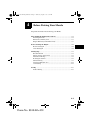
1
Your Vehicle at a Glance
Interior, exterior views and part identification of your Mazda.
Dashboard Overview .................................................................... 1-2
Interior Overview .......................................................................... 1-3
Exterior Overview (4 Door) .......................................................... 1-4
Exterior Overview (5 Door) .......................................................... 1-5
1-1
Form No. 8S18-EA-03I
J48C_8S18-EA-03I_Edition1.book Page 2 Wednesday, August 6, 2003 8:51 AM
Your Vehicle at a Glance
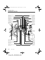
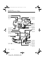
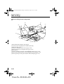
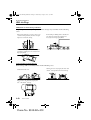
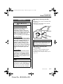
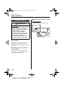
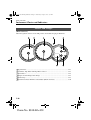
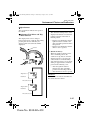
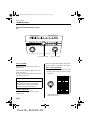
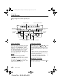
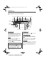
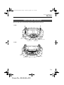
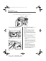
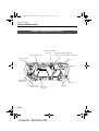
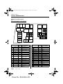
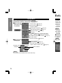
Dashboard Overview
Wiper and washer lever
(page 5-48)
Driver-side air bag
(page 2-36)
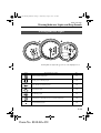
Instrument cluster
(page 5-26)
Lighting control/Turn signals
Information display
(page 6-38)
Hazard warning flasher
(page 5-53)
Audio system
(page 6-10)
Climate control system
(page 5-44)
(page 6-2)
Fog light switch*
Shift lever
(page 5-48)
Power door lock switch
(page 3-8)
(page 5-9)
Passenger-side air bag
(page 2-36)
Glove box
(page 6-42)
Cup holder
(page 6-41)
Power window switches*
(page 3-17)
Hood release handle
(page 3-20)
Audio control switch*
(page 6-32)
Steering column release lever
(page 3-29)
1-2
*Some models.
Form No. 8S18-EA-03I
Parking brake
(page 5-5)
Lighter
(page 6-40)
Ashtray
(page 6-40)
Ignition switch
(page 5-2)
J48C_8S18-EA-03I_Edition1.book Page 3 Wednesday, August 6, 2003 8:51 AM
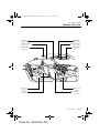
Your Vehicle at a Glance
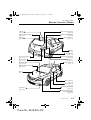
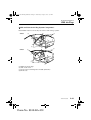
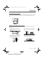
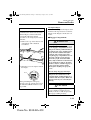
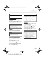
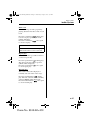
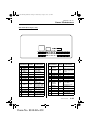
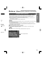
Interior Overview
Sunvisors
(page 6-35)
Curtain air bags*
(page 2-36)
Interior light
Map Lights
(page 6-37)
Rearview mirror
(page 3-27)
Vanity mirror
(page 6-35)
(page 6-35)
Rear seat
Front seats
(page 2-5)
(page 2-2)
Seat belts
Side air bags*
(page 2-9)
(page 2-36)
*Some models.
Form No. 8S18-EA-03I
1-3
J48C_8S18-EA-03I_Edition1.book Page 4 Wednesday, August 6, 2003 8:51 AM
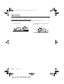
Your Vehicle at a Glance
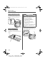
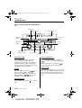
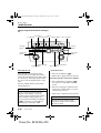
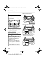
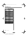
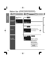
Exterior Overview (4 Door)
Antenna
(page 6-10)
Trunk lid
(page 3-13)
High-mount brake light
(page 8-37)
Rear window defroster
(page 5-52)
Power windows*
(page 3-17)
Tires
(page 8-31)
Fuel-filler lid
(page 3-19)
Brake lights/Taillights
(page 8-37)
License plate light
Rear turn signal lights
(page 8-37)
(page 8-37)
Reverse light
Moonroof*
(page 8-37)
(page 3-22)
Headlights
Child safety locks
(page 8-37)
(page 3-9)
Windshield wiper blades
(page 8-24)
Hood
(page 3-20)
Doors and keys
(page 3-2)
Outside mirrors
(page 3-29)
Fog lights*
Side turn signal lights
(page 8-37)
(page 8-37)
Front turn signal lights/
Side-marker lights
(page 8-37)
1-4
*Some models.
Form No. 8S18-EA-03I
J48C_8S18-EA-03I_Edition1.book Page 5 Wednesday, August 6, 2003 8:51 AM
Your Vehicle at a Glance
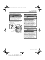
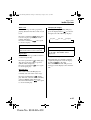
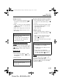
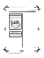
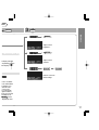
Exterior Overview (5 Door)
Antenna
(page 6-10)
High-mount brake light
(page 8-37)
Liftgate
(page 3-10)
Rear window defroster
(page 5-52)
Brake lights/Taillights
(page 8-37)
Power windows*
(page 3-17)
Tires
(page 8-31)
Fuel-filler lid
(page 3-19)
License plate light
(page 8-37)
Reverse light
Rear turn signal lights
(page 8-37)
Moonroof*
(page 8-37)
(page 3-22)
Headlights
Child safety lock
(page 8-37)
(page 3-9)
Windshield wiper blades
(page 8-24)
Hood
(page 3-20)
Doors and keys
(page 3-2)
Outside mirrors
(page 3-29)
Fog lights*
(page 8-37)
Side turn signal lights
(page 8-37)
Front turn signal lights/
Side-marker lights
(page 8-37)
*Some models.
Form No. 8S18-EA-03I
1-5
J48C_8S18-EA-03I_Edition1.book Page 6 Wednesday, August 6, 2003 8:51 AM
1-6
Form No. 8S18-EA-03I
J48C_8S18-EA-03I_Edition1.book Page 1 Wednesday, August 6, 2003 8:51 AM
2
Essential Safety Equipment
Use of safety equipment, including seats, seat belt system, SRS air
bags and child-restraint systems.
Seats ................................................................................................ 2-2
Front Seats ................................................................................. 2-2
Rear Seat .................................................................................... 2-5
Seat Belt Systems ........................................................................... 2-9
Seat Belt Precautions ................................................................. 2-9
3-Point Type Seat Belt ............................................................. 2-12
Front Seat Belt Pretensioner and Load Limiting Systems ...... 2-14
Rear Center Position Seat Belt ................................................ 2-16
Seat Belt Extender ................................................................... 2-18
Seat Belt Warning Light/Beep ................................................. 2-19
Child Restraint ............................................................................ 2-21
Child Restraint Precautions ..................................................... 2-21
Installing Child-Restraint Systems .......................................... 2-25
LATCH Child-Restraint Systems ............................................ 2-32
SRS Air Bags ............................................................................... 2-36
Supplemental Restraint Systems (SRS) Precautions ............... 2-36
Supplemental Restraint System Components .......................... 2-41
How the Air Bags Work .......................................................... 2-44
2-1
Form No. 8S18-EA-03I
J48C_8S18-EA-03I_Edition1.book Page 2 Wednesday, August 6, 2003 8:51 AM
Essential Safety Equipment
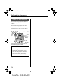
Seats
Front Seats
▼ Seat Slide
WARNING
WARNING
Modification of the Front Seats:
Modifying or replacing the front seats
such as replacing the upholstery or
loosening any bolts is dangerous. The
front seats contain air bag
components essential to the
supplemental restraint system. Such
modification could damage the
supplemental restraint system and
result in serious injury. Consult an
Authorized Mazda Dealer if there is
any need to remove or reinstall the
front seats.
Damaged Front Seats:
Driving with damaged front seats is
dangerous. A collision, even one not
strong enough to inflate the air bags,
could damage the front seats which
contain essential air bag components.
If there was a subsequent collision,
the air bag may not deploy which
could lead to injuries. Always have an
Authorized Mazda Dealer inspect the
front seats, front seat belt
pretensioners and air bags after a
collision.
Securing the Seats:
Adjustable seats and seatbacks that
are not securely locked are
dangerous. In a sudden stop or
collision, the seat or seatback could
move, causing injury. Make sure the
adjustable components of the seat are
locked in place by attempting to slide
the seat forward and backward and
rocking the seatback.
2-2
Form No. 8S18-EA-03I
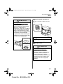
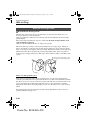
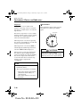
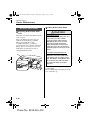
Driver’s Seat Adjustment:
Adjusting the driver’s seat while the
vehicle is moving is dangerous. The
driver could lose control of the vehicle
and have an accident. Adjust the
driver’s seat only when the vehicle is
stopped.
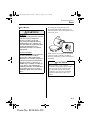
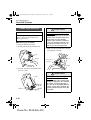
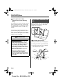
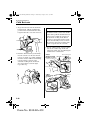
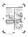
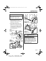
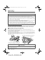
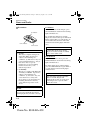
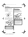
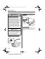
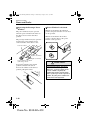
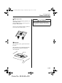
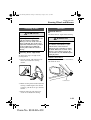
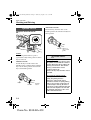
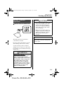
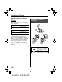
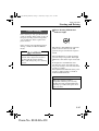
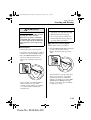
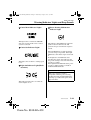
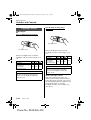
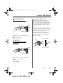
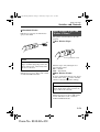
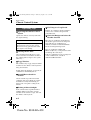
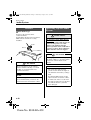
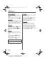
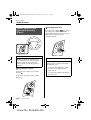
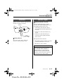
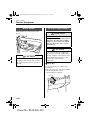
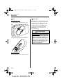
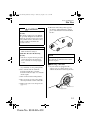
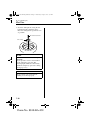
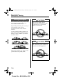
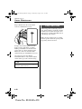
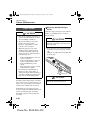
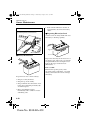
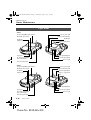
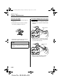
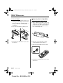
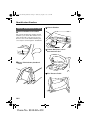
To move a seat forward or backward, raise
the lever and slide the seat to the desired
position and release the lever.
Lever
Make sure the lever returns to its original
position and the seat is locked in place by
attempting to push it forward and
backward.
J48C_8S18-EA-03I_Edition1.book Page 3 Wednesday, August 6, 2003 8:51 AM
Essential Safety Equipment
Seats
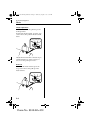
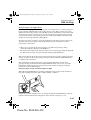
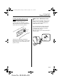
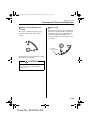
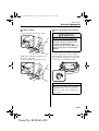
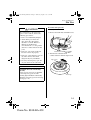
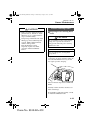
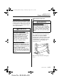
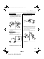
▼ Seat Recline
WARNING
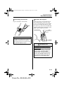
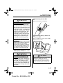
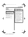
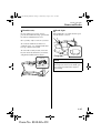
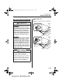
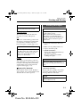
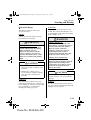
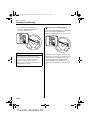
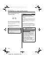
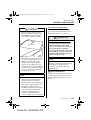
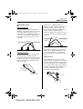
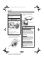
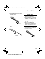
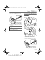
To change the seatback angle, lean
forward slightly while raising the lever.
Then lean back to the desired position and
release the lever.
Reclining:
Sitting in a reclined position while the
vehicle is moving is dangerous
because you don’t get the full
protection from seat belts. During
sudden braking or a collision, you
can slide under the lap belt and suffer
serious internal injuries. For
maximum protection, sit well back
and upright.
Unlocked Seatback:
The seatback plays an important role
in your protection in a vehicle.
Leaving the seatback unlocked is
dangerous as it can allow passengers
to be ejected or thrown around and
baggage to strike occupants in a
sudden stop or collision, resulting in
severe injury. After adjusting the
seatback at any time, even when there
are no other passengers, rock the
seatback to make sure it is locked in
place.
Lever
Make sure the lever returns to its original
position and the seatback is locked in
place by attempting to push it forward and
backward.
CAUTION
When returning a rear-reclined
seatback to its upright position, make
sure you support the seatback while
operating the seatback lever. If the
seatback is not supported, it will flip
forward suddenly and could cause
injury.
2-3
Form No. 8S18-EA-03I
J48C_8S18-EA-03I_Edition1.book Page 4 Wednesday, August 6, 2003 8:51 AM
Essential Safety Equipment
Seats
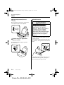
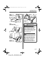
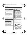
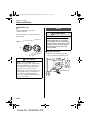
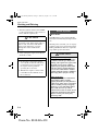
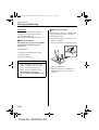
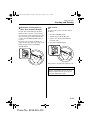
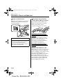
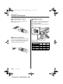
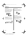
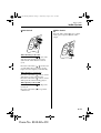
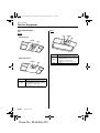
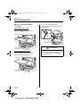
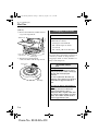
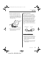
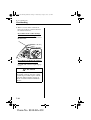
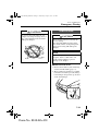
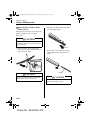
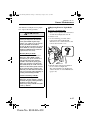
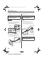
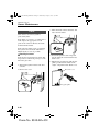
▼ Height Adjustment (Driver’s
Seat)*
By moving the seat lever up or down, the
seat bottom height can be adjusted.
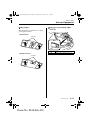
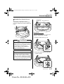
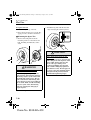
▼ Head Restraint
WARNING
Head Restraints Adjustment:
Driving with the head restraints
adjusted too low or removed is
dangerous. With no support behind
your head, your neck could be
seriously injured in a collision.
Always drive with the head restraints
inserted when seats are being used
and make sure they are properly
adjusted.
Up
Down
Lever
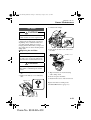
▼ Lumbar Support Adjustment
(Driver’s Seat)*
To adjust the lumbar support, pull the
lever forward.
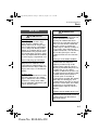
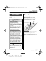
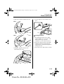
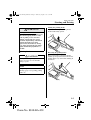
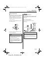
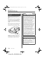
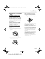
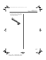
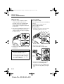
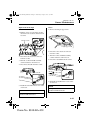
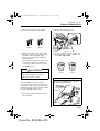
To raise a head restraint, pull it up to the
desired position.
To lower the head restraint, press the stopcatch release, then push the head restraint
down.
Stop-catch release
Lever
Adjust the head restraint so that the top is
parallel with the top of the passenger’s
ears, never the passenger’s neck.
2-4
*Some models.
Form No. 8S18-EA-03I
J48C_8S18-EA-03I_Edition1.book Page 5 Wednesday, August 6, 2003 8:51 AM
Essential Safety Equipment
Seats
Rear Seat
WARNING
Stacking Cargo:
Stacking luggage or other cargo
higher than the seatbacks, and
placing articles on the rear package
tray or on the luggage compartment
cover is dangerous. During sudden
braking or a collision, objects can fly
around and become projectiles that
may hit and injure passengers. Don’t
stack cargo higher than the seatbacks
or on the luggage compartment cover.
Not Securing Luggage and Cargo:
Not securing cargo while driving is
dangerous as it could move or be
crushed during sudden braking or a
collision and cause injury. Make sure
luggage and cargo is secured before
driving.
Securing Seats:
Adjustable seats that are not securely
locked are dangerous. In a sudden
stop or collision, the seat or seatback
could move, causing injury. Make
sure the adjustable components of the
seat are locked in place.
WARNING
Unlocked Seatback:
The seatback plays an important role
in your protection in a vehicle.
Leaving the seatback unlocked is
dangerous as it can allow passengers
to be ejected or thrown around and
baggage to strike occupants in a
sudden stop or collision, resulting in
severe injury. After returning the
seatback at any time, even when there
are no other passengers, rock the
seatback to make sure it is locked in
place.
Passenger on the Folded Seatback:
Driving with a passenger on the
folded seatback is dangerous.
Allowing a child to sit up on the
folded seatback while the vehicle is
moving is particularly dangerous. In
a sudden stop or even a minor
collision, a child not in a proper seat
or child-restraint system and seat belt
could be thrown forward, back or
even out of the car resulting in
serious injuries or death. The child or
other objects in the baggage area
could be thrown into other occupants
and cause serious injury. Never allow
a passenger to sit or stand on the
folded seatback while the vehicle is
moving.
Children and the Folding Rear Seats:
Playing with the folding rear seats is
dangerous. Do not give the car keys to
children and do not allow them to
play in the vehicle.
2-5
Form No. 8S18-EA-03I
J48C_8S18-EA-03I_Edition1.book Page 6 Wednesday, August 6, 2003 8:51 AM
Essential Safety Equipment
Seats
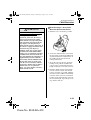
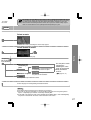
To return the seatbacks to the upright
position
NOTE
When returning a rear seat to its
original position, also replace the seat
belt to its normal position. Verify that
the seat belt pulls and retracts.
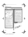
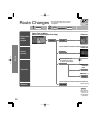
▼ Split-Folding Rear Seatback
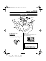
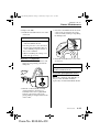
To fold the seatbacks
1. Unfasten the lap portion of the rear
center seat belt (page 2-16).
CAUTION
Always unfasten the lap portion of the
belt before folding the rear-left
seatback. Leaving the lap portion of
the belt fastened could cause damage
to the seat belt, buckle and seatback.
2. Position the outboard seat belts to the
side when folding the seatbacks down.
3. Support the seatback with your hand.
4. Push the rear seatback knob down.
Rear seatback knob
2-6
Form No. 8S18-EA-03I
1. Position the outboard seat belts to the
side.
2. Lift the seatbacks upright.
3. Make sure the seat belts are fully
pulled out from under the seatbacks.
4. Pull on the top of the seatbacks from
inside the vehicle to make sure they are
locked.
5. Fasten the rear-center lap/shoulder belt
and check that all seat belts are routed
properly for passenger use (page 2-16).
WARNING
Seat Belts Caught Under Seatbacks:
A seat belt caught under a seatback
after the seatback is returned to its
upright position is dangerous. In a
collision or sudden stop, the seat belt
cannot provide adequate protection.
Always make sure the seat belts are
fully pulled out from under the
seatbacks.
J48C_8S18-EA-03I_Edition1.book Page 7 Wednesday, August 6, 2003 8:51 AM
Essential Safety Equipment
Seats
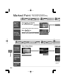
WARNING
Returning Rear Seatbacks to the
Upright Position:
A rear seatback not fully returned
and locked in the upright position is
dangerous. Sudden stops or
maneuvering could cause a seatback
to flip forward suddenly resulting in
injury. If the red indicator is visible
on the back of the rear seatback knob,
the seatback is not locked in the
upright position. When returning the
seatback to the upright position, make
sure there is no red indication.
Locked position
▼ Rear Seatback Lock (4 Door)
To lock or unlock a seatback, move the
lever.
NOTE
The seatback locks are part of the
trunk security system (page 3-15).
Unlocked position
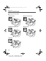
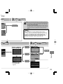
▼ Head Restraint
Red indicator
WARNING
Head Restraints Adjustment:
Driving with the head restraints
adjusted too low or removed is
dangerous. With no support behind
your head, your neck could be
seriously injured in a collision.
Always drive with the head restraints
inserted when seats are being used
and make sure they are properly
adjusted.
2-7
Form No. 8S18-EA-03I
J48C_8S18-EA-03I_Edition1.book Page 8 Wednesday, August 6, 2003 8:51 AM
Essential Safety Equipment
Seats
Height adjustment
To raise a head restraint, pull it up to the
locked position.
To lower the head restraint, press the stopcatch release, then push the head restraint
down.
Stop-catch release
Adjust the head restraint so that the top is
parallel with the top of the passenger’s
ears, never the passenger’s neck.
Removal
To remove the head restraint, press the
stop-catch release, then pull up on the
head restraint.
Stop-catch release
2-8
Form No. 8S18-EA-03I
J48C_8S18-EA-03I_Edition1.book Page 9 Wednesday, August 6, 2003 8:51 AM
Essential Safety Equipment
Seat Belt Systems
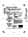
Seat Belt Precautions
Seat belts help to decrease the possibility of severe injury during accidents and sudden
stops. Mazda recommends that the driver and all passengers always wear seat belts.
All of the seat belt retractors are designed to keep the lap/shoulder belts out of the way
when not in use.
The driver’s seat belt has no provisions for child-restraint systems and has only an
emergency locking mode. The driver may wear it comfortably, and it will lock during a
collision.
However, the front passenger’s seat lap/shoulder belt retractors operate in two modes:
emergency locking mode, and for child-restraint systems, automatic locking mode. While
we recommend you put all children in the rear seats, if you must use the front passenger
seat for a child, slide the front passenger seat as far back as possible and make sure the
child-restraint system is secured properly.
WARNING
Not Wearing Seat Belts:
Not wearing a seat belt is extremely dangerous. During a collision, occupants not
wearing seat belts could hit someone or things inside the vehicle or even be thrown
out of the vehicle. They could be seriously injured or even killed. In the same
collision, occupants wearing seat belts would be much safer. Always wear your seat
belt and make sure all occupants are properly restrained.
Seat Belt Damaged During an Accident:
Using a damaged seat belt is dangerous. An accident could damage the belt webbing
of the seat belt in use. A damaged seat belt cannot provide adequate protection in a
collision. Whether a front seat was occupied or not, if the front air bags deployed the
seat belt pretensioners also deployed and both front seat belts must be replaced. Have
an Authorized Mazda Dealer inspect all seat belt systems in use during an accident
before they are used again.
Twisted Seat Belts:
Twisted seat belts are dangerous. In a collision, the full width of the belt isn’t
available to absorb the impact. This puts more force on the bones beneath the belt,
which could cause serious injury or death. Don’t wear twisted seat belts.
2-9
Form No. 8S18-EA-03I
J48C_8S18-EA-03I_Edition1.book Page 10 Wednesday, August 6, 2003 8:51 AM
Essential Safety Equipment
Seat Belt Systems
WARNING
One Belt, One Passenger:
Using one seat belt for more than one person at a time is dangerous. A seat belt used
in this way can’t spread the impact forces properly and the two passengers could be
crushed together and seriously injured or even killed. Never use one belt for more
than one person at a time.
CAUTION
Belt retraction may become difficult if the belts and rings are soiled, so try to keep them
clean.
Ring
▼ Pregnant Women and Persons with Serious Medical Conditions
Pregnant women should wear seat belts. Ask your doctor for specific recommendations.
The lap belt should be worn SNUGLY AND AS LOW AS POSSIBLE OVER THE HIPS.
The shoulder belt should be worn across your shoulder properly, but never across the
stomach area.
Persons with serious medical conditions also should wear seat belts. Check with your
doctor for any special instructions regarding specific medical conditions.
2-10
Form No. 8S18-EA-03I
J48C_8S18-EA-03I_Edition1.book Page 11 Wednesday, August 6, 2003 8:51 AM
Essential Safety Equipment
Seat Belt Systems
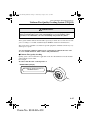
▼ Emergency Locking Mode
If the belt has fully retracted, it will always be in the emergency locking mode until you
move it into automatic locking mode by pulling the belt all the way out to its full length. In
the emergency locking mode, the belt remains comfortable on the occupant and the
retractor will lock in position during a collision.
If the belt feels tight and hinders comfortable movement while the vehicle is stopped or in
motion, you may be in the automatic locking mode because you have pulled the belt too far
out. To return to the more comfortable emergency locking mode, wait until you can stop
the vehicle in a safe level area, retract the belt fully to convert it back to emergency locking
mode and then again extend it around you.
▼ Automatic Locking Mode
Always use the automatic locking mode to keep the child-restraint system from shifting to
an unsafe position in the event of an accident. To get the seat belt into the automatic
locking mode, pull it all the way out and connect it as instructed on the child-restraint
system. It will retract down to the child-restraint system and stay locked on it. See the
section on child restraint (page 2-21).
2-11
Form No. 8S18-EA-03I
J48C_8S18-EA-03I_Edition1.book Page 12 Wednesday, August 6, 2003 8:51 AM
Essential Safety Equipment
Seat Belt Systems
3-Point Type Seat Belt
NOTE
When using the rear center seat belt,
refer to "Rear Center Position Seat
Belt" (page 2-16).
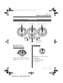
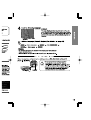
▼ Fastening the Seat Belts
1. Grasp the buckle and tongue.
WARNING
Positioning the Shoulder Portion of
the Seat Belt:
Improper positioning of the shoulder
portion of the seat belt is dangerous.
Always make sure the shoulder
portion of the seat belt is positioned
across your shoulder and near your
neck, but never under your arm, on
your neck, or on your upper arm.
2. Slowly pull out the lap/shoulder belt.
4. Make sure the shoulder belt is snugly
fitted against your body.
Belt
Tongue
Take up slack
Keep low on
hip bone
Too high
3. Insert the tongue into the buckle until
you hear a click.
WARNING
Tongue
Buckle
2-12
Form No. 8S18-EA-03I
Positioning the Lap Portion of the
Seat Belt:
The lap portion of the seat belt worn
too high is dangerous. In a collision,
this would concentrate the impact
force directly on the abdominal area,
causing serious injury. Wear the lap
portion of the belt snugly and as low
as possible.
J48C_8S18-EA-03I_Edition1.book Page 13 Wednesday, August 6, 2003 8:51 AM
Essential Safety Equipment
Seat Belt Systems
▼ Unfastening the Seat Belts
▼ Shoulder Belt Adjuster
Depress the button on the buckle.
Adjust the height of the shoulder belt if
the seat belt touches your neck, or if it
crosses your arm instead of your shoulder.
To raise the shoulder belt adjuster, push
the adjuster up. To lower the shoulder belt
adjuster, pull the button and slide it down.
Make sure the adjuster is locked.
Shoulder belt
adjuster
NOTE
If a belt does not fully retract, inspect it
for kinks and twists. If it is still not
retracting properly, have it inspected at
an Authorized Mazda Dealer.
WARNING
Positioning the Shoulder Portion of
the Seat Belt:
Improper positioning of the shoulder
portion of the seat belt is dangerous.
Always make sure the shoulder
portion of the seat belt is positioned
across your shoulder and near your
neck, but never under your arm, on
your neck, or on your upper arm.
2-13
Form No. 8S18-EA-03I
J48C_8S18-EA-03I_Edition1.book Page 14 Wednesday, August 6, 2003 8:51 AM
Essential Safety Equipment
Seat Belt Systems
Front Seat Belt
Pretensioner and Load
Limiting Systems
For optimum protection, the driver and
front passenger seat belts are equipped
with pretensioner and load limiting
systems.
In moderate or greater frontal or nearfrontal accidents, the front air bag and
pretensioner systems deploy
simultaneously. The pretensioners take up
slack in the front seat belts as the air bags
are expanding. The seat belt pretensioner
system will not activate if the seat belt is
not fastened, only you can be sure it is
worn properly. The load limiting system
releases belt webbing in a controlled
manner to reduce belt force on the
occupant’s chest.
WARNING
Incorrect Positioning of the Driver
and Front Passenger Seat Belts:
Incorrect positioning of the driver
and passenger seat belts is dangerous.
Without proper positioning, the
pretensioner and load limiting
systems cannot provide adequate
protection in an accident and this
could result in serious injury. Wear
seat belts only as recommended in
this owner’s manual.
2-14
Form No. 8S18-EA-03I
WARNING
Expended Seat Belt Pretensioners:
Use of front seat belts with the
pretensioner system expended is
dangerous.
The seat belt pretensioners will only
function once. After they are
expended, they will not work again
and must be replaced immediately.
If the seat belt pretensioners are not
replaced, the risk of injury in a
collision will increase.
Always have an Authorized Mazda
Dealer inspect the seat belt
pretensioners and air bags after any
collision. The seat belt pretensioners
and air bags must be replaced after
any collision, which causes them to
deploy.
Modification or Testing of the
Pretensioner System:
Modifying the components or wiring
of the pretensioner system, including
the use of electronic testing devices is
dangerous. You could accidentally
activate it or make it inoperable which
would prevent it from activating in an
accident. The occupants or repairers
could be seriously injured. Never
modify the components or wiring, or
use electronic testing devices on the
pretensioner system.
J48C_8S18-EA-03I_Edition1.book Page 15 Wednesday, August 6, 2003 8:51 AM
Essential Safety Equipment
Seat Belt Systems
WARNING
Pretensioner System Disposal:
Improper disposal of the pretensioner
system or a vehicle with nondeactivated pretensioners is
dangerous. Unless all safety
procedures are followed, injury could
result. Ask an Authorized Mazda
Dealer how to safely dispose of the
pretensioner system or how to scrap a
pretensioner-equipped vehicle.
NOTE
• The pretensioner system will only
activate in a moderate or greater
frontal or near-frontal collision. It
will not activate in most rollovers,
side or rear impacts.
• Some smoke (non-toxic gas) will be
released when the air bags and
pretensioners deploy. This does not
indicate a fire. This gas normally
has no effect on occupants,
however, those with sensitive skin
may experience light skin irritation.
If residue from the deployment of
the air bags or the front pretensioner
system gets on the skin or in the
eyes, wash it off as soon as possible.
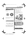
▼ Air Bag/Front Seat Belt
Pretensioner System Warning
Light
If the air bag/front seat belt pretensioner
system is OK, the warning light
illuminates when the ignition switch is
turned to the ON position or after the
engine is cranked. After about 6 seconds it
goes out.
A system malfunction is indicated when
the warning light stays on or doesn’t
illuminate at all when the ignition switch
is turned to the ON position. If any of
these occur, consult an Authorized Mazda
Dealer as soon as possible. The system
may not work in an accident.
WARNING
Self-Servicing the Air Bag/
Pretensioner Systems:
Self-servicing or tampering with the
systems is dangerous. An air bag/
pretensioner could accidentally
activate or become disabled. This
could cause serious injuries. Never
tamper with the systems and always
have an Authorized Mazda Dealer
performs all servicing and repairs.
2-15
Form No. 8S18-EA-03I
J48C_8S18-EA-03I_Edition1.book Page 16 Wednesday, August 6, 2003 8:51 AM
Essential Safety Equipment
Seat Belt Systems
▼ Air Bag/Front Seat Belt
Pretensioner System Warning
Beep
If a malfunction is detected in the air bag/
front seat belt pretensioner systems and
the warning light, a warning beep sound
will be heard for about 5 seconds every
minute.
The air bag and seat belt pretensioner
system warning beep sound will continue
to be heard for approximately 35 minutes.
Have your vehicle inspected at an Mazda
Dealer as soon as possible.
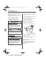
Rear Center Position Seat
Belt
Before using the rear-center lap/shoulder
belt make sure tongue (A) and anchor
buckle (B) are fastened.
(A)
(B)
WARNING
Air Bag/Front Seat Belt Pretensioner
System Warning Beep:
Driving the vehicle with the air bag/
front seat belt pretensioner system
warning beep sounding is dangerous.
In a collision, the air bags and the
front seat belt pretensioner system
will not deploy and this could result in
death or serious injury.
Do not drive the vehicle with the air
bag/front seat belt pretensioner
system warning beep sounding.
Contact an Authorized Mazda Dealer
to have the vehicle inspected as soon
as possible.
2-16
Form No. 8S18-EA-03I
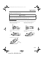
▼ Fastening the Seat Belt
1. Grasp the buckle (D) and tongue (C).
2. Slowly pull out the lap/shoulder belt.
3. Insert the tongue (C) into the buckle
(D) until you hear a click.
(C)
(A)
(D)
(B)
J48C_8S18-EA-03I_Edition1.book Page 17 Wednesday, August 6, 2003 8:51 AM
Essential Safety Equipment
Seat Belt Systems
WARNING
Fastening the Rear-Center Seat Belt
with Only One Buckle:
Fastening the rear-center seat belt
with only one buckle is dangerous. If
only one pair of seat belt tongue and
buckle, either tongue (A) and anchor
buckle (B) or tongue (C) and anchor
buckle (D), is fastened, the seat belt
cannot provide full protection. In a
sudden stop or collision, the user
could slide under the belt and suffer
serious injuries. Always make sure
that both pairs of seat belt tongues
and buckles are fastened properly.
Positioning the Shoulder Portion of
the Seat Belt:
Improper positioning of the shoulder
portion of the seat belt is dangerous.
Always make sure the shoulder
portion of the seat belt is positioned
across your shoulder and near your
neck, but never under your arm, on
your neck, or on your upper arm.
▼ Unfastening the Seat Belt
Depress the button on the buckle.
▼ Unfastening the Lap Portion of
the Seat Belt
Insert a small object in the anchor buckle
(B) slot, such as a key.
(A)
(B)
4. Make sure the shoulder belt is snugly
fitted against your body.
WARNING
Positioning the Lap Portion of the
Seat Belt:
The lap portion of the seat belt worn
too high is dangerous. In a collision,
this would concentrate the impact
force directly on the abdominal area,
causing serious injury. Wear the lap
portion of the belt snugly and as low
as possible.
CAUTION
Always unfasten the lap portion of the
belt before folding the rear-left
seatback. Leaving the lap portion of
the belt fastened could cause damage
to the seat belt, buckle and seatback.
2-17
Form No. 8S18-EA-03I
J48C_8S18-EA-03I_Edition1.book Page 18 Wednesday, August 6, 2003 8:51 AM
Essential Safety Equipment
Seat Belt Systems
NOTE
To encourage rear seat passengers to
wear their seat belts, we suggest
leaving the rear center lap position of
the belt fastened at all times except
when folding the rear seat forward.
▼ Fastening the Lap Portion of the
Seat Belt
Grasp tongue (A) and insert it into the
anchor buckle (B) until you hear a click. It
is now secure for passenger use.
NOTE
After returning the rear-left seatback to
its upright position, fasten the lap
portion of the belt.
Seat Belt Extender
If your seat belt is not long enough, even
when fully extended, a seat belt extender
may be available to you at no charge from
your Authorized Mazda Dealer.
This extender will be only for you and for
the particular vehicle and seat. Even if it
plugs into other seat belts, it may not hold
in the critical moment of a crash.
When ordering an extender, only order
one that provides the necessary additional
length to fasten the seat belt properly.
Please contact your Authorized Mazda
Dealer for more information.
WARNING
Unnecessary Use of an Extender:
Using a seat belt extender when not
necessary is dangerous. The seat belt
will be too long and not fit properly.
In an accident, the seat belt will not
provide adequate protection and you
could be seriously injured. Only use
the extender when it is required to
fasten the seat belt properly.
Using an Improper Extender:
Using a seat belt extender that is for
another person or a different vehicle
or seat is dangerous. The seat belt will
not provide adequate protection and
the user could be seriously injured in
an accident. Only use the extender
provided for you and for the
particular vehicle and seat. NEVER
use the extender in a different vehicle
or seat.
2-18
Form No. 8S18-EA-03I
J48C_8S18-EA-03I_Edition1.book Page 19 Wednesday, August 6, 2003 8:51 AM
Essential Safety Equipment
Seat Belt Systems
WARNING
Using an Extender That is Too Long:
Using an extender that is too long is
dangerous. The seat belt will not fit
properly. In an accident, the seat belt
will not provide adequate protection
and you could be seriously injured.
Don’t use the extender or choose one
shorter in length if the distance
between the extender’s buckle and the
center of the user’s body is less than
15cm (6 in).
NOTE
When not in use, remove the seat belt
extender and store it in the vehicle. If
the seat belt extender is left connected,
the seat belt warning light will not
illuminate and function properly.
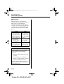
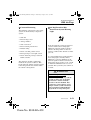
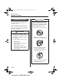
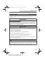
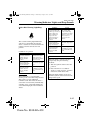
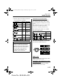
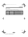
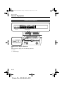
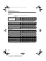
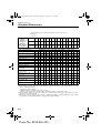
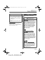
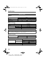
Seat Belt Warning Light/
Beep
The seat belt warning light illuminates
and a beep sound will be heard if the
driver’s seat belt is not fastened when the
ignition switch is turned to the ON
position.
Conditions of operation
Condition
The driver’s seat belt is
not fastened when the
ignition switch is turned
to the ON position.
The driver’s seat belt is
fastened while the
warning light and the
beep are activated.
The driver’s seat belt is
fastened before the
ignition switch is turned
to the ON position.
Result
The warning light
illuminates for about
1 minute and a beep
sound will be heard
for about 6 seconds.
The warning light
turns off and the
beep sound stops.
The warning light
will not illuminate
and the beep sound
will not be heard.
2-19
Form No. 8S18-EA-03I
J48C_8S18-EA-03I_Edition1.book Page 20 Wednesday, August 6, 2003 8:51 AM
Essential Safety Equipment
Seat Belt Systems
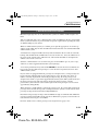
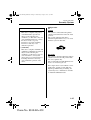
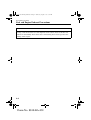
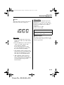
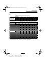
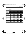
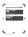
▼ Belt Minder
The belt minder is a supplemental
warning to the seat belt warning function.
This feature provides additional
reminders to the driver that the driver’s
seat belt is not fastened by intermittently
sounding a beep sound and flashing the
seat belt warning light in the instrument
cluster.
Condition
The driver’s seat belt is
not fastened when the
vehicle speed reaches 8
km/h (5 mph) and about 1
minute has elapsed since
the ignition switch was
turned to the ON position.
The driver’s seat belt is
fastened while the
warning light and the
beep are activated.
The driver’s seat belt is
fastened before the
ignition switch is turned
to the ON position.
Result
The warning light
flashes and the beep
sound will be heard
for about 6 seconds
every 30 seconds,
for a period of about
5 minutes.
The warning light
turns off and the
beep sound stops.
The warning light
will not illuminate
and the beep sound
will not be heard.
NOTE
The belt minder can be deactivated
temporarily using the following
methods:
1. Turn the ignition switch to the ON
position.
2. Fasten the driver’s seat belt for
about 2 seconds or longer, and then
unfasten it within 20 seconds.
The belt minder will be deactivated
until the ignition switch is turned to the
ON position again.
2-20
Form No. 8S18-EA-03I
J48C_8S18-EA-03I_Edition1.book Page 21 Wednesday, August 6, 2003 8:51 AM
Essential Safety Equipment
Child Restraint
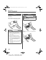
Child Restraint Precautions
Mazda strongly urges the use of child-restraint systems for children small enough to use
them.
You are required by law to use a child-restraint system for children in the U.S. and Canada.
Check your local and state or provincial laws for specific requirements regarding the safety
of children riding in your vehicle.
Whatever child-restraint system you consider, please pick the appropriate one for the age
and size of the child, obey the law and follow the instructions that come with the individual
child-restraint system.
A child who has outgrown child-restraint systems should sit in the rear and use seat belts,
both lap and shoulder. If the shoulder belt crosses the neck or face, move the child closer to
the center of the vehicle in the outboard seats, and towards the buckle on the right if the
child is seated on the center seat.
Statistics confirm that the rear seat is the best place for all children up to 12 years of age,
and more so with a supplemental restraint system (air bags).
A rear-facing child-restraint system should NEVER be used on the front seat with the air
bag system activated. The front passenger’s seat is also the least preferred seat for other
child-restraint systems.
If your vehicle is equipped with front passenger seat weight sensors, a front passenger air
bag deactivation indicator light is also equipped (page 2-29). To reduce the chance of
injuries caused by deployment of the front passenger air bag, the front passenger seat
weight sensors work as a part of the supplemental restraint system. This system deactivates
the front passenger front and side air bags and also the front passenger seat belt
pretensioner system when the total seated weight on the front passenger seat is less than
approximately 30 kg (66 lb).
When an infant or small child sits on the front passenger seat, the system shuts off the front
passenger front and side air bags and seat belt pretensioner system, so make sure the front
passenger air bag deactivation indicator light illuminates.
Even if the front passenger air bag is shut off, Mazda strongly recommends that children be
properly restrained and child-restraint systems of all kinds are properly secured on the rear
seats which are the best place for children.
For more details, refer to "Front passenger seat weight sensors (page 2-44)".
2-21
Form No. 8S18-EA-03I
J48C_8S18-EA-03I_Edition1.book Page 22 Wednesday, August 6, 2003 8:51 AM
Essential Safety Equipment
Child Restraint
WARNING
Proper Size of Child-Restraint System:
For effective protection in vehicle accidents and sudden stops, a child must be
properly restrained using a seat belt or child-restraint system depending on age and
size. If not, the child could be seriously injured or even killed in an accident.
Follow the Manufacturer’s Instructions and Always Keep the Child-Restraint System
Buckled Down:
An unsecured child-restraint system is dangerous. In a sudden stop or a collision it
could move causing serious injury or death to the child or other occupants. Make sure
the child-restraint system is properly secured in place according to the child-restraint
system manufacturer’s instructions. When not in use, remove it from the vehicle or
fasten it with a seat belt, or latch it down to BOTH LATCH lower anchors for LATCH
child-restraint systems.
Holding a Child While the Vehicle is Moving:
Holding a child in your arms while the vehicle is moving is extremely dangerous. No
matter how strong the person may be, he or she cannot hold onto a child in a sudden
stop or collision and it could result in serious injury or death to the child or other
occupants. Even in a moderate accident, the child may be exposed to air bag forces
that could result in serious injury or death to the child, or the child may be slammed
into the adult, injuring the adult. Always secure a child in a proper child-restraint
system.
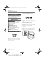
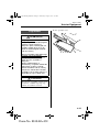
Rear-Facing Child-Restraint System:
Rear-facing child-restraint systems on the front seat are particularly dangerous.
The child-restraint system can be hit by a deploying air bag and moved violently
backward resulting in serious injury or death to the child. Even though you may feel
assured that the front passenger air bag will not deploy based on the fact that the front
passenger air bag deactivation indicator light illuminates, NEVER use a rear-facing
child-restraint system in the front seat with an air bag that could deploy even in a
moderate collision.
Deploying air bag
2-22
Form No. 8S18-EA-03I
J48C_8S18-EA-03I_Edition1.book Page 23 Wednesday, August 6, 2003 8:51 AM
Essential Safety Equipment
Child Restraint
WARNING
Seating Children in a Child-Restraint System on the Front Passenger Seat:
If your vehicle is equipped with front passenger seat weight sensors, a front passenger
air bag deactivation indicator light is also equipped (page 2-29). Even with the front
passenger seat weight sensors, if you must use the front passenger seat for children,
seating a child in a child-restraint system on the front passenger seat under the
following conditions increases the danger of the front passenger air bag deploying
and could result in serious injury or death to the child.
• The total seated weight of the child with the child-restraint system on the front
passenger seat is approximately 30 kg (66 lb) or more.
• Luggage or other items are placed on the seat with the child in the child-restraint
system.
• A rear passenger or luggage push or pull down on the front passenger seatback.
• A rear passenger steps on the front passenger seat rails with the feet.
• Luggage or other items are placed on the seatback or hung on the head restraint.
• The seat is washed.
• Liquids are spilled on the seat.
• The front passenger seat is moved backward, pushing into luggage or other items
placed behind it.
• The front passenger seatback contacts the rear seat.
• Luggage or other items are placed between the front passenger seat and driver seat.
• Any accessories which might increase the total seated weight on the front
passenger seat are attached to the front passenger seat.
The designated positions with seat belts on the rear seats are the safest places for
children. Always use seat belts and child restraints.
Children and Seating Position with Side and Curtain Air Bags:
Allowing anyone to lean over or against the front door, the area of front seat, front
and rear window pillars and the roof edge along both sides which the side and curtain
air bags deploy even though using a child-restraint system is dangerous. If the vehicle
is equipped with side and curtain air bags, the impact of inflation could cause serious
injury or death to the child. Furthermore, leaning over or against the front door could
block the side and curtain air bags and eliminate the advantages of supplemental
protection. With the front air bag and the additional side air bag that comes out of the
front seat, the rear seat is always a better location for children. Do not allow a child to
lean over or against the doors, even if the child is seated in a child-restraint system.
2-23
Form No. 8S18-EA-03I
J48C_8S18-EA-03I_Edition1.book Page 24 Wednesday, August 6, 2003 8:51 AM
Essential Safety Equipment
Child Restraint
WARNING
One Belt, One Passenger:
Using one seat belt for more than one person at a time is dangerous. A seat belt used
in this way can’t spread the impact forces properly and the two passengers could be
crushed together and seriously injured or even killed. Never use one belt for more
than one person at a time.
CAUTION
A seat belt or child-restraint system can become very hot in a closed vehicle during
warm weather. To avoid burning yourself or a child, check them before you or your child
touches them.
NOTE
Your Mazda is equipped with LATCH lower anchors for attachment of specially
designed LATCH child-restraint systems in the rear seat. When using these anchors to
secure a child-restraint system, refer to "LATCH Child-Restraint Systems" (page 2-32).
2-24
Form No. 8S18-EA-03I
J48C_8S18-EA-03I_Edition1.book Page 25 Wednesday, August 6, 2003 8:51 AM
Essential Safety Equipment
Child Restraint
Installing Child-Restraint
Systems
Accident statistics reveal that a child is
safer in the rear seat. The front
passenger’s seat is clearly the worst
choice for any child under 12, and with
rear-facing child-restraint systems it is
clearly unsafe due to air bags.
▼ Rear Seat Child-Restraint
System Installation
Follow these instructions when using a
child-restraint system, unless you are
attaching a LATCH-equipped childrestraint system to the rear LATCH lower
anchors. Refer to "LATCH ChildRestraint Systems" (page 2-32).
NOTE
Some child-restraint systems now come
with tethers and therefore must be
installed on the seats that take tethers to
be effective. In your Mazda, tethered
child-restraint systems can only be
accommodated in the three positions on
the rear seat.
Some child-restraint systems also employ
specially designed LATCH attachments;
refer to "LATCH Child-Restraint
Systems" (page 2-32).
WARNING
Tethered Child-Restraint Systems
Work Only on Tether-Equipped Rear
Seats:
Installation of a tether equipped
child-restraint system in the front
passenger’s seat defeats the safety
design of the system and will result in
an increased chance of serious injury
if the child-restraint system goes
forward without benefit of being
tethered.
Place tether equipped child-restraint
systems where there are tether
anchors.
Follow the child-restraint system
manufacturer’s instructions carefully.
If you are not sure whether you have a
LATCH system or tether, check in the
child-restraint system manufacturer’s
instructions and follow them
accordingly. Depending on the type of
child-restraint system, it may not
employ seat belts which are in
automatic locking mode.
1. Make sure the seatback is securely
latched by rocking the seatback.
2. Secure the child-restraint system with
the lap portion of the lap/shoulder belt.
See the manufacturer’s instructions on
the child-restraint system for belt
routing instructions.
2-25
Form No. 8S18-EA-03I
J48C_8S18-EA-03I_Edition1.book Page 26 Wednesday, August 6, 2003 8:51 AM
Essential Safety Equipment
Child Restraint
3. To get the retractor into the automatic
locking mode, pull the shoulder belt
portion of the seat belt until the entire
length of the belt is out of the retractor.
NOTE
Inspect this function before each use of
the child-restraint system. You should
not be able to pull the shoulder belt out
of the retractor while the system is in
the automatic locking mode. When
you remove the child-restraint system,
be sure the belt fully retracts to return
the system to emergency locking mode
before occupants use the seat belts.
5. If your child-restraint system requires
the use of a tether strap, hook and
tighten the tether strap by following the
manufacturer’s instructions.
4. Push the child-restraint system firmly
into the vehicle seat. Be sure the belt
retracts as snugly as possible. Clicking
from the retractor will be heard during
retraction if the system is in the
automatic locking mode. If the belt
does not lock the seat down tight,
repeat this step.
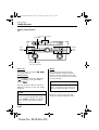
4 Door
Anchor bracket
location
For rear center seat
For rear left seat
Anchor
bracket
For rear right seat
Cover
4 Door
Tether strap
position
Anchor
bracket
2-26
Form No. 8S18-EA-03I
Tether
strap
J48C_8S18-EA-03I_Edition1.book Page 27 Wednesday, August 6, 2003 8:51 AM
Essential Safety Equipment
Child Restraint
Tether
strap
5 Door
Anchor bracket
location
(Outboard position)
For rear left seat
For rear right seat
5 Door
Tether strap position
(Outboard position)
Tether strap
For rear
center seat
5 Door
Anchor bracket
location
(Center position)
Cover
For rear
center seat
5 Door
Tether strap
position
(Center position)
WARNING
Child-Restraint Tether Usage:
Using the tether or tether anchor to
secure anything but a child-restraint
system is dangerous. This could
weaken or damage the tether or tether
anchor and result in injury. Use the
tether and tether anchor only for a
child-restraint system.
Incorrect Positioning of the Tether
Strap:
Positioning the tether strap on top of
the head restraint is dangerous. In a
collision, the head restraint could
bend or break. This will cause the
strap to loosen. The child-restraint
system could move and injure the
child or someone else. Always
position the tether strap between the
head restraint and the seatback.
2-27
Form No. 8S18-EA-03I
J48C_8S18-EA-03I_Edition1.book Page 28 Wednesday, August 6, 2003 8:51 AM
Essential Safety Equipment
Child Restraint
▼ If You Must Use the Front Seat
for Children
If you cannot put all children in the rear
seat, at least put the smallest children in
the rear and be sure the largest child up
front uses the shoulder belt over the
shoulder.
Do not put rear-facing child-restraint
systems on the front passenger’s seat.
This seat is also not set up for tethered
child-restraint systems, put them in one of
the rear seat positions set up with tether
anchors.
Likewise the LATCH child-restraint
system cannot be secured in the front
passenger’s seat and should be used in the
rear seat.
Don’t allow anyone to sleep against the
right front or rear doors if you have an
optional side and curtain air bag, it could
cause serious injuries to an out of position
occupant. As children more often sleep in
cars, it is better to put them in the rear
seat. If installing the child-restraint
system on the front seat is unavoidable,
follow these instructions when using a
front-facing child-restraint system in the
front passenger’s seat.
NOTE
• To check if your front seats have
side air bags:
Every Mazda side air bag will have
a "SRS-Air Bag" label on the
outboard shoulder of the front seats.
• To check if your vehicle has curtain
air bags:
Every Mazda curtain air bag will
have an "SRS-Air Bag" marking on
the front and rear window pillars
along the roof edge.
2-28
Form No. 8S18-EA-03I
WARNING
Front Passenger’s Seat Position:
As your vehicle has front air bags and
doubly so if your vehicle has side air
bags, a front-facing child-restraint
system should be put on the front seat
only when it is unavoidable.
Even if the front passenger air bag
deactivation indicator light
illuminates, always move the seat as
far back as possible, because the force
of a deploying air bag could cause
serious injury or death to the child.
Rear-Facing Child-Restraint System:
The child-restraint system can be hit
by a deploying air bag and moved
violently backward resulting in
serious injury or death to the child.
Even though you may feel assured
that the front passenger air bag will
not deploy based on the fact that the
front passenger air bag deactivation
indicator light illuminates, NEVER
use a rear-facing child-restraint
system in the front seat with an air
bag that could deploy even in a
moderate collision.
J48C_8S18-EA-03I_Edition1.book Page 29 Wednesday, August 6, 2003 8:51 AM
Essential Safety Equipment
Child Restraint
WARNING
Children and Seating Position with
Side and Curtain Air Bags:
Allowing anyone to lean over or
against the front door, the area of
front seat, front and rear window
pillars and the roof edge along both
sides which the side and curtain air
bags deploy even though using a
child-restraint system is dangerous. If
the vehicle is equipped with side and
curtain air bags, the impact of
inflation could cause serious injury
or death to the child. Furthermore,
leaning over or against the front door
could block the side and curtain air
bags and eliminate the advantages of
supplemental protection. With the
front air bag and the additional side
air bag that comes out of the front
seat, the rear seat is always a better
location for children. Do not allow a
child to lean over or against the
doors, even if the child is seated in a
child-restraint system.
▼ Front Passenger’s Seat ChildRestraint System Installation
1. Slide the seat as far back as possible.
2. Secure the child-restraint system with
the lap portion of the lap/shoulder belt.
See the manufacturer’s instructions on
the child-restraint system for belt
routing instructions.
3. To get the retractor into the automatic
locking mode, pull the shoulder belt
portion of the seat belt until the entire
length of the belt is out of the retractor.
4. Push the child-restraint system firmly
into the vehicle seat. Be sure the belt
retracts as snugly as possible. Clicking
from the retractor will be heard during
retraction if the system is in automatic
locking mode. If the belt does not lock
the seat down tight, repeat the previous
step and also this one.
2-29
Form No. 8S18-EA-03I
J48C_8S18-EA-03I_Edition1.book Page 30 Wednesday, August 6, 2003 8:51 AM
Essential Safety Equipment
Child Restraint
NOTE
• Inspect this function before each
use of the child-restraint system.
You should not be able to pull the
shoulder belt out of the retractor
while the system is in the automatic
locking mode. When you remove
the child-restraint system, be sure
the belt fully retracts to return the
system to emergency locking mode
before occupants use the seat belts.
• Follow the child-restraint system
manufacturer’s instructions
carefully.
Depending on the type of childrestraint system, it may not employ
seat belts which are in automatic
locking mode.
2-30
Form No. 8S18-EA-03I
5. Make sure the front passenger air bag
deactivation indicator light illuminates
after installing a child-restraint system
on the front passenger seat.
J48C_8S18-EA-03I_Edition1.book Page 31 Wednesday, August 6, 2003 8:51 AM
Essential Safety Equipment
Child Restraint
WARNING
Seating a Child in a Child-Restraint
System on the Front Passenger Seat
With the Front Passenger Air Bag
Deactivation Indicator Light Not
Illuminated:
Seating a child in a child-restraint
system installed on the front
passenger seat with the front
passenger air bag deactivation
indicator light not illuminated is
dangerous. If the front passenger air
bag deactivation indicator light does
not illuminate even when the total
seated weight is less than
approximately 30 kg (66 lb), this
means that the front passenger front
and side air bags, and seat belt
pretensioner are ready for
deployment. If an accident were to
deploy an air bag, a child sitting in
the front passenger seat could be
seriously injured or killed. If the front
passenger air bag deactivation
indicator light does not illuminate
after installing a child-restraint
system on the front passenger seat,
install the child-restraint system on
the rear seat and consult an
Authorized Mazda Dealer as soon as
possible. While it is always better to
install any child-restraint system on
the rear seat, it is essential to do so if
the front passenger air bag
deactivation indicator light does not
illuminate. For further details, refer
to "Front passenger seat weight
sensors (page 2-44)".
2-31
Form No. 8S18-EA-03I
J48C_8S18-EA-03I_Edition1.book Page 32 Wednesday, August 6, 2003 8:51 AM
Essential Safety Equipment
Child Restraint
LATCH Child-Restraint Systems
Your Mazda is equipped with LATCH lower anchors for attachment of specially designed
LATCH child-restraint systems in the rear outboard seats. Both anchors must be used,
otherwise the seat will bounce around and put the child in danger. Some LATCH childrestraint systems must also be used in conjunction with a tether to be effective. If they have
a tether you must use it to better assure your child’s safety.
WARNING
Manufacturer’s Instructions for Child-Restraint System:
An unsecured child-restraint system is dangerous. In a sudden stop or a collision it
could move causing serious injury or death to the child or other occupants. Make sure
the child-restraint system is properly secured in place according to the child-restraint
system manufacturer’s instructions.
Attaching Two Child-Restraint Systems to the Same LATCH Lower Anchor:
Attaching two child-restraint systems to the same LATCH lower anchor is dangerous.
In a collision, one anchor may not be strong enough to hold two child-restraint system
attachments and may break, causing serious injury or death. If you use the seat
position for another child-restraint system when an outboard LATCH position is
occupied, use the center seat belts instead, and the tether if tether-equipped.
Unsecured Child-Restraint System:
An unsecured child-restraint system is dangerous. In a sudden stop or a collision it
could move causing serious injury or death to the child or other occupants. Follow the
child-restraint system manufacturer’s instructions on belt routing to secure the seat
just as you would with a child in it so that nobody is tempted to put a child in an
improperly secured seat later on. When not in use, remove it from the vehicle or fasten
it with a seat belt, or latch it down to BOTH LATCH lower anchors for LATCH childrestraint systems.
LATCH Child-Restraint Systems:
Not following the child-restraint system manufacturer’s instructions when installing
the child-restraint system is dangerous. If seat belts or a foreign object prevent the
child-restraint system from being securely attached to the LATCH lower anchors and
the child-restraint system is installed improperly, the child-restraint system could
move in a sudden stop or collision causing serious injury or death to the child or other
occupants. When installing the child-restraint system, make sure there are no seat
belts or foreign objects near or around the LATCH lower anchors. Always follow the
child-restraint system manufacturer’s instructions.
2-32
Form No. 8S18-EA-03I
J48C_8S18-EA-03I_Edition1.book Page 33 Wednesday, August 6, 2003 8:51 AM
Essential Safety Equipment
Child Restraint
▼ Child-Restraint System
Installation Procedure (Rear
Outboard Seats)
1. Make sure the seatback is securely
latched by rocking the seatback.
2. Expand the area between the seat
bottom and the seatback slightly to
verify the locations of the LATCH
lower anchors.
Marking
4. If your child-restraint system came
equipped with a tether, that probably
means it is very important to properly
secure the tether for child safety, please
carefully follow the child-restraint
system manufacturer’s instructions
when installing tethers.
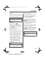
For rear left seat
4 Door
Anchor bracket
location
For rear right seat
For rear
left seat
Anchor
bracket
LATCH
lower anchor
Cover
For rear
right seat
4 Door
Tether strap
position
Tether
strap
NOTE
The markings above the LATCH lower
anchors indicate the locations of
LATCH lower anchors for the
attachment of a child-restraint system.
3. Secure the child-restraint system using
BOTH LATCH lower anchors,
following the child-restraint system
manufacturer’s instruction.
Anchor
bracket
5 Door
Anchor bracket
location
(Outboard position)
For rear left seat
For rear right seat
2-33
Form No. 8S18-EA-03I
J48C_8S18-EA-03I_Edition1.book Page 34 Wednesday, August 6, 2003 8:51 AM
Essential Safety Equipment
Child Restraint
5 Door
Tether strap position
(Outboard position)
Tether strap
WARNING
Child-Restraint Tether Usage:
Using the tether or tether anchor to
secure anything but a child-restraint
system is dangerous. This could
weaken or damage the tether or tether
anchor and result in injury. Use the
tether and tether anchor only for a
child-restraint system.
Incorrect Positioning of the Tether
Strap:
Positioning the tether strap on top of
the head restraint is dangerous. In a
collision, the head restraint could
bend or break. This will cause the
strap to loosen. The child-restraint
system could move and injure the
child or someone else. Always
position the tether strap between the
head restraint and the seatback.
▼ Child-Restraint System
Installation Procedure (Rear
Center Seat)
The LATCH lower anchors at the center
of the rear seat are much further apart than
the sets of LATCH lower anchors for
child-restraint system installation at other
seating positions. Child-restraint systems
with rigid LATCH attachments cannot be
installed on the center seating position.
Some LATCH equipped child-restraint
systems can be placed in the center
position and will reach the nearest
LATCH lower anchors which are 400 mm
(15.75 in) apart. LATCH compatible
child-restraint systems (with attachments
on belt webbing) can be used at this
seating position only if the child-restraint
system manufacturer’s instructions state
that the child-restraint system can be
installed to LATCH lower anchors that are
400 mm (15.75 in) apart. Do not attach
two child-restraint systems to the same
LATCH lower anchor. If your childrestraint system has a tether, it must also
be used for your child’s optimum safety.
1. Make sure the seatback is securely
latched by rocking the seatback.
2. Expand the area between the seat bottom
and the seatback slightly to verify the
locations of the LATCH lower anchors.
Marking
For rear center seat
LATCH
lower anchor
2-34
Form No. 8S18-EA-03I
J48C_8S18-EA-03I_Edition1.book Page 35 Wednesday, August 6, 2003 8:51 AM
Essential Safety Equipment
Child Restraint
NOTE
The markings above the LATCH lower
anchors indicate the locations of
LATCH lower anchors for the
attachment of a child-restraint system.
3. Secure the child-restraint system using
BOTH LATCH lower anchors,
following the child-restraint system
manufacturer’s instructions.
For rear
center seat
5 Door
Anchor bracket
location
(Center position)
4. If your child-restraint system came
equipped with a tether, that probably
means it is very important to properly
secure the tether for child safety, please
carefully follow the child-restraint
system manufacturer’s instructions
when installing tethers.
Cover
Tether
strap
For rear
center seat
5 Door
Tether strap
position
(Center position)
4 Door
Anchor bracket
location
Anchor
bracket
For rear center seat
Cover
4 Door
Tether strap
Tether strap
position
(Center position)
WARNING
Child-Restraint Tether Usage:
Using the tether or tether anchor to
secure anything but a child-restraint
system is dangerous. This could
weaken or damage the tether or tether
anchor and result in injury. Use the
tether and tether anchor only for a
child-restraint system.
Anchor
bracket
2-35
Form No. 8S18-EA-03I
J48C_8S18-EA-03I_Edition1.book Page 36 Wednesday, August 6, 2003 8:51 AM
Essential Safety Equipment
SRS Air Bags
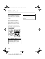
Supplemental Restraint Systems (SRS) Precautions
The front and side supplemental restraint systems (SRS) include up to 6 air bags (verify
"SRS AIRBAG" location indicator marks).
They are located in:
• The steering wheel hub (driver air bag)
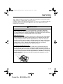
• The front passenger dashboard (front passenger air bag)
• The outboard sides of the front seatbacks (side air bags)*
• The front and rear window pillars, and the roof edge along both sides (curtain air bags)*
These systems operate independently depending on the type of accident encountered; if
you have side and curtain air bags, the side and curtain air bags are not likely to deploy on
both sides in the same accident because a vehicle is not often hit from both sides. The side
and curtain air bags and the frontal air bag system will not normally deploy during the
same type of accident unless a combination of frontal and side impacts occur.
The air bag supplemental restraint systems are designed to provide supplemental protection
only in the front seats in certain situations and the rear outside passenger positions only in
same-side collisions, so seat belts are always important in the following ways:
Without seat belt usage, the air bags cannot provide adequate protection during an accident.
Seat belt usage is necessary to:
• Keep the passenger away from an inflating air bag.
• Reduce the possibility of injuries during an accident that is not designed for air bag
inflation, such as roll-over or rear impact.
• Reduce the possibility of injuries in frontal or side collisions that are not severe enough
to activate the air bags.
• Reduce the possibility of being thrown from your vehicle.
• Reduce the possibility of injuries to lower body and legs during an accident because the
air bags provide no protection to these parts.
• Hold the driver in a position which allows better control of the vehicle.
2-36
*Some models.
Form No. 8S18-EA-03I
J48C_8S18-EA-03I_Edition1.book Page 37 Wednesday, August 6, 2003 8:51 AM
Essential Safety Equipment
SRS Air Bags
Small children should be protected by a child-restraint system. In certain regions, larger
children must use a child-restraint system (page 2-21).
Carefully consider which child-restraint system is necessary for your child and follow the
installation directions in this Owner’s Manual as well as the child-restraint system
manufacturer’s instructions.
WARNING
Air Bags without Seat Belts:
Depending only on the air bags for protection during an accident is dangerous.
Alone, air bags may not prevent serious injuries. The appropriate air bags can be
expected to inflate only in collisions with frontal, near frontal or side forces that are at
least moderate. Vehicle occupants should always wear seat belts.
Child in the Front Seat:
Placing a child, 12 years or under, in the front seat is dangerous. The child could be
hit by a deploying air bag and be seriously injured or even killed. Even if the front
passenger air bag deactivation indicator light illuminates, always move the front
passenger seat as far back as possible. A sleeping child is more likely to lean against
the door and be hit by the side air bag in a moderate, right-side collision. Whenever
possible, always secure a child 12 years and under on the rear seat with an
appropriate child-restraint system for the child’s age and size.
Rear-Facing Child-Restraint System:
Rear-facing child-restraint systems on the front seat are particularly dangerous.
The child-restraint system can be hit by a deploying air bag and moved violently
backward resulting in serious injury or death to the child. Even though you may feel
assured that the front passenger air bag will not deploy based on the fact that the front
passenger air bag deactivation indicator light illuminates, NEVER use a rear-facing
child-restraint system in the front seat with an air bag that could deploy even in a
moderate collision.
Deploying air bag
2-37
Form No. 8S18-EA-03I
J48C_8S18-EA-03I_Edition1.book Page 38 Wednesday, August 6, 2003 8:51 AM
Essential Safety Equipment
SRS Air Bags
WARNING
Seating Position with Front Air Bags:
Sitting too close to the air bag modules or placing hands or feet on them is extremely
dangerous. Front air bags inflate with great force and speed. Serious injuries could
occur if someone is too close. The driver should always hold onto only the rim of the
steering wheel. The front seat passenger should keep both feet on the floor. Front seat
occupants should adjust their seats as far back as possible and always sit upright
against the seatbacks with seat belts worn properly.
Seating Position with Side and Curtain Air Bags:
Sitting too close to the side air bag modules or placing hands on them is extremely
dangerous. The side air bags inflate with great force and speed directly out of the
outboard side of the front seat and expand along the front door on the side the car is
hit. Serious injury could occur if someone is sitting too close to the door or leaning
against a window, or if rear seat occupants grab the sides of the front seatbacks.
Furthermore, sleeping up against the door or hanging out the windows in the vehicle
could block the side and curtain air bags and eliminate the advantages of
supplemental protection. Give the side and curtain air bags room to work by sitting in
the center of the seat while the vehicle is moving with seat belts worn properly.
Front Air Bag Modules:
Attaching an object to the front air bag modules or placing something in front of them
is dangerous. In an accident, the object could interfere with front air bag inflation
and injure the occupants.
Always keep the front air bag modules free of objects.
Side Air Bag Modules:
Attaching things to the front seat in such a way as to cover the outboard side of the
seat in any way is dangerous. In an accident the object could interfere with the side
air bag, which inflates from the outboard side of the front seats, impeding the added
protection of the side air bag system or redirecting the air bag in a way that is
dangerous. Furthermore, the bag could be cut open spewing exhaust.
Do not hang net bags, map pouches or backpacks with side straps on the front seats.
Never use seat covers on the front seats. Always keep the side air bag modules in your
front seats free to deploy in the event of a side collision.
2-38
Form No. 8S18-EA-03I
J48C_8S18-EA-03I_Edition1.book Page 39 Wednesday, August 6, 2003 8:51 AM
Essential Safety Equipment
SRS Air Bags
WARNING
Curtain Air Bag Modules:
Attaching objects to the areas where the curtain air bag activates such as on the
windshield glass, side door glass, front and rear window pillars and along the roof
edge and assist grips is dangerous. In an accident the object could interfere with the
curtain air bag, which inflates from the front and rear window pillars and along the
roof edge, impeding the added protection of the curtain air bag system or redirecting
the air bag in a way that is dangerous. Furthermore, the bag could be cut open
spewing exhaust.
Do not place hangers or any other objects on the assist grips. When hanging clothes,
hang them on the coat hook directly. Always keep the curtain air bag modules free to
deploy in the event of a side collision.
Hot Air Bag Inflators:
Hot air bag inflators are dangerous. Immediately after inflation, the inflators in the
steering wheel, dashboard, seatbacks, or the front and rear window pillars and along
the roof edge are very hot. You could get burned. Don’t touch the internal components
of the air bag modules after the bags have inflated.
Installation of Front-End Equipment:
Installation of front-end equipment, such as frontal protection bar (kangaroo bar,
bull bar, push bar, etc.), snowplow, or winches, is dangerous. The air bag crash sensor
system could be affected. This could cause air bags to inflate unexpectedly, or it could
prevent the air bags from inflating during an accident. Front occupants could be
seriously injured. Never install any front-end equipment to your vehicle.
Suspension Adjustment:
Adjusting the vehicle suspension is dangerous. If the vehicle’s height or the
suspension is changed, the vehicle will be unable to accurately detect a collision
resulting in incorrect or unexpected air bag deployment and the possibility of serious
injuries.
2-39
Form No. 8S18-EA-03I
J48C_8S18-EA-03I_Edition1.book Page 40 Wednesday, August 6, 2003 8:51 AM
Essential Safety Equipment
SRS Air Bags
WARNING
Modification of the Supplemental Restraint System:
Modifying the components or wiring of the supplemental restraint system is
dangerous. You could accidentally activate it or make it inoperable. Don’t make any
modifications to the supplemental restraint system. This includes installing trim,
badges, or anything else over the air bag modules. It also includes installing extra
electric equipment on or near system components or wiring. An Authorized Mazda
Dealer can provide the special care needed in the removal and installation of front
seats. It is important to protect the air bag wiring and connections to assure that the
bags do not accidentally deploy, the driver seat slide position sensor and front
passenger seat weight sensors are not damaged and that the seats retain an
undamaged air bag connection.
NOTE
• When an air bag deploys, a loud inflation noise can be heard and some smoke will be
released. Neither is likely to cause injury, however, the texture of the air bags may
cause light skin injuries on body parts not covered with clothing through friction.
• Should you sell your Mazda, we urge you to tell the new owner of its air bag systems
and that familiarization with all instructions about them, from the Owner’s Manual, is
important.
2-40
Form No. 8S18-EA-03I
J48C_8S18-EA-03I_Edition1.book Page 41 Wednesday, August 6, 2003 8:51 AM
Essential Safety Equipment
SRS Air Bags
Supplemental Restraint System Components
The supplemental restraint systems (SRS) have two basic subsystems:
• The air bag system with inflators and air bags.
• The electric system with crash sensors and diagnostic module.
The air bags are mounted in the following locations:
• The steering wheel hub
• The front passenger dashboard
• The outboard sides of the front seatbacks
• The front and rear window pillars, and the roof edge along both sides
The air bags are out of sight until activated.
2-41
Form No. 8S18-EA-03I
J48C_8S18-EA-03I_Edition1.book Page 42 Wednesday, August 6, 2003 8:51 AM
Essential Safety Equipment
SRS Air Bags
▼ Front Air Bag System Components
(6)
(1)
(3)
(4)
(8)
(7)
(9)
(2)
(5)
(8)
(1) Front dual stage inflators and air bags
(2) Crash sensors and diagnostic module (SAS unit)
(3) Front air bag sensor
(4) Driver seat slide position sensor (page 2-44)
(5) Front passenger seat weight sensors (page 2-44)
(6) Front seats
(7) Driver and front passenger seat belt buckle switches (page 2-44)
(8) Front seat belt pretensioner and load limiting systems (page 2-14)
(9) Front passenger air bag deactivation indicator light (page 2-44)
2-42
Form No. 8S18-EA-03I
J48C_8S18-EA-03I_Edition1.book Page 43 Wednesday, August 6, 2003 8:51 AM
Essential Safety Equipment
SRS Air Bags
▼ Side and Curtain Air Bag System Components*
Put children in the rear seats, they do not have side air bag systems.
4 Door
(4)
(1)
(2)
(3)
(4)
5 Door
(1)
(1)
(1)
(3)
(2)
(1) Inflators and air bags
(2) Side crash sensor
(3) Crash sensors and diagnostic module (SAS unit)
(4) Front seats
*Some models.
Form No. 8S18-EA-03I
2-43
J48C_8S18-EA-03I_Edition1.book Page 44 Wednesday, August 6, 2003 8:51 AM
Essential Safety Equipment
SRS Air Bags
How the Air Bags Work
▼ How the Front Air Bags Work
When air bag crash sensors detect a frontal impact of greater than moderate force, an
electrical current is sent to the inflators.
Gases are produced to inflate the front air bags and after the inflation, the front air bags
quickly deflate.
The front air bags will function only once. After that, the front air bags will not work
again and must be replaced.
Only an Authorized Mazda Dealer can replace the systems.
The front, dual stage air bags control air bag inflation in two energy stages. During an
impact of moderate severity the front air bags deploy with lesser energy, whereas during
more severe impacts, they deploy with more energy. Deployment of the front air bags may
differ between the driver and the front passenger depending on the driver seat position,
front passenger weight and front seat belt usage, which allow for further controlling of the
system.
The front air bags will deploy only
in a frontal or frontal offset impact.
Driver seat slide position sensor
Your vehicle is equipped with a driver seat slide sensor as a part of the supplemental
restraint system. The sensor is located under the driver seat. The sensor determines whether
the driver seat is fore or aft of a reference position and sends the seat position to the crash
sensors and diagnostic module (SAS unit). The sensor is also designed to control the
deployment of the driver air bag depending on how close the driver seat is to the steering
wheel.
The air bag/front seat belt pretensioner system warning light flashes if the sensor has a
possible malfunction (page 2-53).
2-44
Form No. 8S18-EA-03I
J48C_8S18-EA-03I_Edition1.book Page 45 Wednesday, August 6, 2003 8:51 AM
Essential Safety Equipment
SRS Air Bags
Front passenger seat weight sensors
If your vehicle is equipped with front passenger seat weight sensors, a front passenger air
bag deactivation indicator light is also equipped (page 2-29). These sensors are located
under both of the front passenger seat rails. These sensors determine the total seated weight
on the front passenger seat. The sensors are also designed to prevent the front passenger
front and side air bags and seat belt pretensioner system from inflating if the total seated
weight is less than approximately 30 kg (66 lb).
To reduce the chance of injuries caused by deployment of the front passenger air bag, the
system deactivates the front passenger front and side air bags and also the seat belt
pretensioner system when:
• There is no passenger in the front passenger seat. (The front passenger air bag
deactivation indicator light does not illuminate.)
• The total seated weight on the front passenger seat is less than approximately 30 kg (66
lb). (The front passenger air bag deactivation indicator light illuminates.)
This system shuts off the front passenger front and side air bags and seat belt pretensioner
system, so make sure the front passenger air bag deactivation indicator light illuminates
according to the chart below.
The air bag/front seat belt pretensioner system warning light flashes and the front
passenger air bag deactivation indicator light illuminates if the sensors have a possible
malfunction. If this happens, the front passenger front and side air bags and seat belt
pretensioner system will not deploy.
Front passenger air bag deactivation indicator light
This indicator light illuminates to remind you that the front passenger front and side air
bags and seat belt pretensioner will not deploy during a collision.
If the front passenger weight sensors are normal, the indicator light illuminates when the
ignition switch is turned to the ON position. After about 6 seconds it goes out.
2-45
Form No. 8S18-EA-03I
J48C_8S18-EA-03I_Edition1.book Page 46 Wednesday, August 6, 2003 8:51 AM
Essential Safety Equipment
SRS Air Bags
The front passenger air bag deactivation indicator light illuminates or is off under the
following conditions:
Total seated weight on
the front passenger seat
Empty (Not occupied)*
Less than approx. 30 kg
(66 lb)
Approx. 42 kg (93 lb) or
more
*
Front passenger air bag
deactivation indicator
light
OFF
Front passenger front and
side air bags
Seat belt pretensioner
system
OFF
OFF
ON
OFF
OFF
OFF
ON
ON
If the front passenger seat belt is buckled, the front passenger air bag deactivation
indicator light illuminates, however this does not indicate a malfunction.
If the front passenger air bag deactivation indicator light does not illuminate when the
ignition switch is turned to the ON position and does not illuminate as indicated in the
above chart, do not allow a child to sit in the front passenger seat and consult an Authorized
Mazda Dealer as soon as possible. The system may not work properly in an accident.
WARNING
Decreasing the Total Seated Weight on the Front Passenger Seat:
When an adult or large child sits on the front passenger seat, decreasing the total
seated weight on the front passenger seat from the total seated weight of
approximately 42 kg (93 lb) required for air bag deployment is dangerous. The front
passenger seat weight sensors will detect the reduced total seated weight condition and
the front passenger front and side air bags and seat belt pretensioner system will not
deploy during an accident. The front passenger will not have the supplementary
protection of the air bag, which could result in serious injury. Decreasing the total
seated weight on the front passenger seat from the total seated weight of
approximately 42 kg (93 lb) could result in an air bag not deploying under the
following conditions, for example:
• A rear passenger pushes up on the front passenger seat with the feet.
• Luggage or other items placed under the front passenger seat or between the front
passenger seat and driver seat that push up the front passenger seat bottom.
• The front passenger seat occupant sits in a manner that does not place the entire
weight of the occupant on the seat such as by sitting too close to the door, grasping
the rim of the moonroof.
• The front passenger seatback contacts the rear seat.
• Any accessories which might decrease the total seated weight on the front
passenger seat are attached to the front passenger seat.
2-46
Form No. 8S18-EA-03I
J48C_8S18-EA-03I_Edition1.book Page 47 Wednesday, August 6, 2003 8:51 AM
Essential Safety Equipment
SRS Air Bags
WARNING
Increasing the Total Seated Weight on the Front Passenger Seat:
When an infant or small child sits on the front passenger seat, increasing the total
seated weight on the front passenger seat from the total seated weight of
approximately 30 kg (66 lb) is dangerous. The front passenger seat weight sensors will
detect the increased total seated weight, which could result in the unexpected
deployment of the front passenger front and side air bags and seat belt pretensioner
system in an accident and serious injury. Increasing the total seated weight on the
front passenger seat from the total seated weight of approximately 30 kg (66 lb) could
result in the front passenger front and side air bags and seat belt pretensioner system
deployment in an accident under the following conditions, for example:
• Luggage or other items are placed on the seat with the child in the child-restraint
system.
• A rear passenger or luggage push or pull down on the front passenger seatback.
• A rear passenger steps on the front passenger seat rails with the feet.
• Luggage or other items are placed on the seatback or hung on the head restraint.
• The seat is washed.
• Liquids are spilled on the seat.
• The front passenger seat is moved backward, pushing into luggage or other items
placed behind it.
• The front passenger seatback contacts the rear seat.
• Luggage or other items are placed between the front passenger seat and driver seat.
• Any accessories which might increase the total seated weight on the front
passenger seat are attached to the front passenger seat.
CAUTION
• To assure proper deployment of the front air bag and to prevent damage to the sensors
in the front seat bottoms:
• Do not place sharp objects on the front seat bottoms or leave heavy luggage on them.
• Do not spill any liquids on the front seats or under the front seats.
• To allow the sensors to function properly, always perform the following:
• Adjust the front seats as far back as possible and always sit upright against the
seatbacks with seat belts worn properly.
• If you place your child on the front passenger seat, secure the child-restraint system
properly and slide the front passenger seat as far back as possible (page 2-29).
2-47
Form No. 8S18-EA-03I
J48C_8S18-EA-03I_Edition1.book Page 48 Wednesday, August 6, 2003 8:51 AM
Essential Safety Equipment
SRS Air Bags
NOTE
• The system requires about 10 seconds to alternate between turning the front
passenger front and side air bags and seat belt pretensioner system on or off.
• The front passenger air bag deactivation indicator light may illuminate repeatedly if
luggage or other items are put on the front passenger seat, or if the temperature of the
vehicle’s interior changes suddenly.
• The front passenger air bag deactivation indicator light may illuminate for 10 seconds
if the total seated weight on the front passenger seat changes.
• If the front passenger air bag deactivation indicator light does not illuminate after
installing a child-restraint system on the front passenger seat, install the child-restraint
system on the rear seat and consult an Authorized Mazda Dealer as soon as possible.
Driver and front passenger buckle switches
The buckle switches on the front seat belts detect whether or not the front seat belts are
securely fastened and further control the deployment of the air bags on the front seats.
▼ How the Side and Curtain Air Bags Work*
When air bag crash sensors detect a side impact of greater than moderate force, an
electrical current is sent to the inflators.
Gases are produced to inflate the side and curtain air bags and after the inflation, the side
and curtain air bags quickly deflate.
The side and curtain air bags will function only once. After that, the side and curtain air
bags will not work again and must be replaced. Only an Authorized Mazda Dealer can
replace the systems.
The curtain air bag will deploy only on the side
the vehicle receives the force of the impact.
The side air bag will deploy only on the side
the vehicle receives the force of the impact.
CAUTION
To prevent damage to the side and curtain air bag wiring, don’t place luggage or other
objects under the front seats.
2-48
*Some models.
Form No. 8S18-EA-03I
J48C_8S18-EA-03I_Edition1.book Page 49 Wednesday, August 6, 2003 8:51 AM
Essential Safety Equipment
SRS Air Bags
▼ Air Bag Activation/Deactivation
CAUTION
If the front passenger seat weight sensors detect a total seated weight on the front
passenger seat of less than approximately 42 kg (93 lb), the front passenger front and
side air bags and seat belt pretensioner may not inflate (page 2-44).
Front air bag activation
A greater than moderate impact will cause the front air bags to inflate in the following cases:
Hitting a solid wall straight on at greater
than about 22 km/h (14 mph).
Frontal impact within about a 30 degree
range from head-on to the vehicle.
Hitting a curb, pavement edge or hard
object.
Driving into a big hole or hitting the far
side of a hole.
Landing hard or the vehicle falling.
2-49
Form No. 8S18-EA-03I
J48C_8S18-EA-03I_Edition1.book Page 50 Wednesday, August 6, 2003 8:51 AM
Essential Safety Equipment
SRS Air Bags
Limitations to front air bag activation
Depending on the severity of impact, the front air bags may not inflate in the following
cases:
Impacts involving trees or poles cause severe
cosmetic damage but may not have enough
impact to activate the air bag.
Rear-ending or running under a truck's tail
gate may not provide the stopping force
necessary for air bag deployment.
Frontal offset impact to the vehicle may not
provide the stopping force necessary for air
bag deployment.
Non-activation of front air bags
Front air bags will not normally inflate in the following cases:
Collision from the rear.
Impact to the side, but it may deploy the
side* and curtain* air bags.
2-50
*Some models.
Form No. 8S18-EA-03I
Vehicle roll-over, may deploy the side* and
curtain* air bags but not the front air bags.
J48C_8S18-EA-03I_Edition1.book Page 51 Wednesday, August 6, 2003 8:51 AM
Essential Safety Equipment
SRS Air Bags
Side and curtain air bag activation*
Greater than moderate impact to one side of the vehicle (driver or passenger side areas) will
cause the side and curtain air bags to inflate, but it will not normally deploy the front air
bags.
Limitations to side and curtain air bag activation*
Depending on the severity of impact, the side and curtain air bags may not inflate in the
following cases:
Frontal offset impact may not provide
enough side impact to deploy the side* and
curtain* air bags.
Vehicle roll-over may not provide enough
side force to deploy the side* and curtain*
air bags.
Side impacts involving trees or poles can
cause severe cosmetic damage but may not
have enough impact force to activate the
side* and curtain* air bags.
Side impacts with two-wheeled vehicles
may not provide enough force to deploy the
side* and curtain* air bags.
*Some models.
Form No. 8S18-EA-03I
2-51
J48C_8S18-EA-03I_Edition1.book Page 52 Wednesday, August 6, 2003 8:51 AM
Essential Safety Equipment
SRS Air Bags
Non-activation of side and curtain air bag*
The side and curtain air bags will not normally inflate in the following cases:
Collision from the rear.
2-52
*Some models.
Form No. 8S18-EA-03I
Collision from the front, but it may deploy
the front air bags.
J48C_8S18-EA-03I_Edition1.book Page 53 Wednesday, August 6, 2003 8:51 AM
Essential Safety Equipment
SRS Air Bags
▼ Constant Monitoring
The following components of the air bag
systems are monitored by a diagnostic
system:
▼ Air Bag/Front Seat Belt
Pretensioner System Warning
Light
• SAS unit
• Front air bag sensor
• Air bag modules
• Side crash sensor*
• Front seat belt pretensioners
• Related wiring
• Driver seat slide position sensor
• Front passenger seat weight sensors
• Driver and front passenger seat belt
buckle switches
The diagnostic module continuously
monitors the system’s readiness. This
begins when the ignition switch is turned
to the ON position and continues while
the vehicle is being driven.
If the air bag/front seat belt pretensioner
system is normal, the warning light
illuminates when the ignition switch is
turned to the ON position or after the
engine is cranked. After about 6 seconds it
goes out.
A system malfunction is indicated when
the warning light constantly flashes,
illuminates or doesn’t illuminate at all
when the ignition switch is turned to the
ON position. If any of these occur, consult
an Authorized Mazda Dealer as soon as
possible. The system may not work in an
accident.
WARNING
Self-Servicing the Air Bag/
Pretensioner Systems:
Self-servicing or tampering with the
systems is dangerous. An air bag/
pretensioner could accidentally
activate or become disabled. This
could cause serious injuries. Never
tamper with the systems and always
have an Authorized Mazda Dealer
perform all servicing and repairs.
*Some models.
Form No. 8S18-EA-03I
2-53
J48C_8S18-EA-03I_Edition1.book Page 54 Wednesday, August 6, 2003 8:51 AM
Essential Safety Equipment
SRS Air Bags
▼ Air Bag/Front Seat Belt
Pretensioner System Warning
Beep
If a malfunction is detected in the air bag/
front seat belt pretensioner systems and
the warning light, a warning beep sound
will be heard for about 5 seconds every
minute.
The air bag and seat belt pretensioner
system warning beep sound will continue
to be heard for approximately 35 minutes.
Have your vehicle inspected at an Mazda
Dealer as soon as possible.
WARNING
Air Bag/Front Seat Belt Pretensioner
System Warning Beep:
Driving the vehicle with the air bag/
front seat belt pretensioner system
warning beep sounding is dangerous.
In a collision, the air bags and the
front seat belt pretensioner system
will not deploy and this could result in
death or serious injury.
Do not drive the vehicle with the air
bag/front seat belt pretensioner
system warning beep sounding.
Contact an Authorized Mazda Dealer
to have the vehicle inspected as soon
as possible.
2-54
Form No. 8S18-EA-03I
▼ Maintenance
The air bag systems do not require regular
maintenance. But if any of the following
occurs, take your vehicle to an Authorized
Mazda Dealer as soon as possible:
• The air bag system warning light
flashes.
• The air bag system warning light
illuminates.
• The air bag system warning light does
not illuminate when the ignition switch
is turned to the ON position.
• The air bags inflate.
• Front passenger air bag deactivation
indicator light does not illuminate
when the ignition switch is turned to
the ON position or does not illuminate
as indicated in the chart. For more
details about this indicator light and
this chart, refer to "Front passenger
seat weight sensors (page 2-44)".
J48C_8S18-EA-03I_Edition1.book Page 55 Wednesday, August 6, 2003 8:51 AM
Essential Safety Equipment
SRS Air Bags
WARNING
Damaged Air Bag System
Components:
Driving with damaged air bag system
components is dangerous. A collision,
even one not strong enough to inflate
the air bags, could damage the system
components. If there was a
subsequent collision, a damaged
component would not inflate the air
bags. Always have an Authorized
Mazda Dealer inspect the air bag
systems after a collision.
NOTE
If it becomes necessary to have the
components or wiring system for the
supplementary restraint system
modified to accommodate a person
with certain medical conditions in
accordance with a certified physician,
contact an Authorized Mazda Dealer,
refer to "Customer Assistance
(U.S.A.)" (page 9-2).
Removing Interior Parts:
Removing any components such as
the front seats (if side air bags are
equipped), front dashboard, the
steering wheel or parts on the front
and rear window pillars and along the
roof edge, containing air bag parts or
sensors is dangerous. These parts
contain essential air bag components.
The air bag could accidentally
activate and cause serious injuries.
Always have an Authorized Mazda
Dealer remove these parts.
Air Bag Disposal:
Improper disposal of an air bag or a
vehicle with live air bags in it can be
extremely dangerous. Unless all
safety procedures are followed, injury
can result. Ask an Authorized Mazda
Dealer how to safely dispose of an air
bag or how to scrap an air bag
equipped vehicle.
2-55
Form No. 8S18-EA-03I
J48C_8S18-EA-03I_Edition1.book Page 56 Wednesday, August 6, 2003 8:51 AM
2-56
Form No. 8S18-EA-03I
J48C_8S18-EA-03I_Edition1.book Page 1 Wednesday, August 6, 2003 8:51 AM
3
Knowing Your Mazda
Explanation of basic operations and controls; opening/closing and
adjustment of various parts.
Doors and Locks ............................................................................ 3-2
Keys ........................................................................................... 3-2
Keyless Entry System* .............................................................. 3-3
Door Locks ................................................................................ 3-7
Liftgate (5 Door) ..................................................................... 3-10
Trunk Lid (4 Door) .................................................................. 3-13
Inside Trunk Release Slide Lever (4 Door) ............................. 3-16
Power Windows* ..................................................................... 3-17
Fuel-Filler Lid and Cap ........................................................... 3-19
Hood ........................................................................................ 3-20
Moonroof* ............................................................................... 3-22
Security System ........................................................................... 3-24
Immobilizer System ................................................................ 3-24
Theft-Deterrent System* ......................................................... 3-27
Steering Wheel and Mirrors ...................................................... 3-29
Steering Wheel ........................................................................ 3-29
Mirrors ..................................................................................... 3-29
*Some models.
Form No. 8S18-EA-03I
3-1
J48C_8S18-EA-03I_Edition1.book Page 2 Wednesday, August 6, 2003 8:51 AM
Knowing Your Mazda
Doors and Locks
Keys
The keys operate all locks.
WARNING
Keys and Children:
Leaving children in a vehicle with the
key is dangerous. This could result in
someone being badly injured or even
killed. They could play with power
windows or other controls, or even
make the vehicle move. Don’t leave
the keys in your vehicle with children
and keep them in a place where your
children will not find or play with
them.
Key code number plate
A code number is stamped on the plate
attached to the key set; detach this plate
and store it in a safe place (not in the
vehicle) for use if you need to make a
replacement key.
NOTE
(With immobilizer system)
Refer to Immobilizer System (page 3-24)
for information regarding keys and
engine starting on vehicles equipped
with the immobilizer system.
3-2
Form No. 8S18-EA-03I
Also write down the code number and
keep it in another safe and handy place,
but not in the vehicle.
If your key is lost, consult your
Authorized Mazda Dealer with the code
number ready.
J48C_8S18-EA-03I_Edition1.book Page 3 Wednesday, August 6, 2003 8:51 AM
Knowing Your Mazda
Doors and Locks
Keyless Entry System*
This system locks and unlocks the doors
and the liftgate.
It can also help you signal for attention in
an emergency.
Press the button slowly and accurately.
CAUTION
To avoid damage to the transmitter, do
not:
• Drop it.
• Get it wet.
• Disassemble it.
• Expose it to heat or sunlight.
NOTE
• The keyless entry system is
designed to operate up to about 2.5
m (8 ft) from the center of the
vehicle, but this may vary because
of local conditions.
• The system doesn’t operate when
the key is in the ignition switch.
• Doors cannot be locked by pressing
the LOCK button while any other
door is open. The hazard warning
lights will also not flash.
• If the transmitter does not operate
when pressing a button or the
operation range becomes too small,
the battery may be dead. To install a
new battery, refer to Maintenance
(page 3-5).
• Additional transmitters can be
obtained at an Authorized Mazda
Dealer. Up to 3 transmitters can be
used with the keyless entry system
per vehicle. Bring all transmitters to
an Authorized Mazda Dealer when
the electronic codes need to be
reset.
*Some models.
Form No. 8S18-EA-03I
3-3
J48C_8S18-EA-03I_Edition1.book Page 4 Wednesday, August 6, 2003 8:51 AM
Knowing Your Mazda
Doors and Locks
▼ Transmitter
Lock button
Lock button
To lock the doors and the liftgate, press
the LOCK button and the hazard warning
lights will flash once.
To confirm that all the doors and the
liftgate have been locked, press the LOCK
button again within 5 seconds. If they are
closed and locked, the horn will sound
and the hazard warning lights will flash
once.
Unlock button
Panic button
NOTE
NOTE
• (U.S.A.)
This device complies with part 15
of the FCC Rules. Operation is
subject to the following two
conditions: (1) This device may not
cause harmful interference, and (2)
this device must accept any
interference received, including
interference that may cause
undesired operation.
• (CANADA)
This device complies with RSS-210
of Industry CANADA. Operation is
subject to the following two
conditions: (1) this device may not
cause interference, and (2) this
device must accept any interference,
including interference that may
cause undesired operation of the
device.
NOTE
If the LOCK and UNLOCK buttons
are pressed sequentially, the hazard
warning lights may not flash correctly.
3-4
Form No. 8S18-EA-03I
Confirm that all the doors and the
liftgate are locked visually or audibly
by use of the double click.
Unlock button
To unlock the driver’s door, press the
UNLOCK button and the hazard warning
lights will flash twice.
To unlock all the doors and the liftgate,
press the UNLOCK button again within 5
seconds and the hazard warning lights
will flash twice.
NOTE
After unlocking with the transmitter,
all doors and the liftgate will
automatically lock if one of the doors
or the liftgate is not opened within
about 30 seconds.
J48C_8S18-EA-03I_Edition1.book Page 5 Wednesday, August 6, 2003 8:51 AM
Knowing Your Mazda
Doors and Locks
Panic button
You can use the button to turn on the
alarm, which allows you to signal for
attention in an emergency.
NOTE
The alarm will work whether any door
or the liftgate is open or closed.
Turning on the alarm
Pressing the button once will trigger the
alarm for about 2 minutes and 30 seconds,
and do the following:
• The horn sounds intermittently.
• The hazard warning lights flash.
Turning off the alarm
Press any button on the transmitter.
▼ Transmitter Maintenance
CAUTION
• Make sure the battery is installed
with the correct pole facing upward.
Battery leakage could occur if it is
not installed correctly.
• When replacing the battery, be
careful not to bend the electrical
terminals or get oil on them. Also
be careful not to get dirt in the
transmitter as it could damage it.
• Danger of battery explosion if it is
incorrectly replaced.
• Replace only with the same type
battery (CR2025 or equivalent).
• Dispose of used batteries according
to the following instructions.
• Insulate the plus and minus
terminals of the battery using
cellophane or equivalent tape.
• Never disassemble.
• Never throw the battery into fire
and/or water.
• Never deform or crush.
3-5
Form No. 8S18-EA-03I
J48C_8S18-EA-03I_Edition1.book Page 6 Wednesday, August 6, 2003 8:51 AM
Knowing Your Mazda
Doors and Locks
Replacing the transmitter battery
1. Insert a small screwdriver into the slot
and gently pry open the transmitter.
3. Install a new battery (CR2025 or
equivalent) into the front portion of the
holder with the positive pole ( )
facing up. Press on the B portion of the
battery to set the battery.
Back cover
Slot
Back cover
B
Front
cover
2. Press the portion of the battery
indicated by A and remove the battery.
Front of
holder
4. Align the front and back covers and
snap the transmitter shut.
▼ Service
A
If you have a problem with the keyless
entry system, consult an Authorized
Mazda Dealer.
If your transmitter is lost or stolen, bring
all remaining transmitters to an
Authorized Mazda Dealer as soon as
possible for a replacement and to make
the lost or stolen transmitter inoperative.
CAUTION
Changes or modifications not
expressly approved by the party
responsible for compliance could void
the user’s authority to operate the
equipment.
3-6
Form No. 8S18-EA-03I
J48C_8S18-EA-03I_Edition1.book Page 7 Wednesday, August 6, 2003 8:51 AM
Knowing Your Mazda
Doors and Locks
Door Locks
WARNING
Unattended Children and Pets:
Leaving a child or an animal
unattended in a parked vehicle is
dangerous. In hot weather,
temperatures inside a vehicle can
become high enough to cause brain
damage or even death. Always take all
children and animals with you or
leave a responsible person with them.
Keys and Children:
Leaving children in a vehicle with the
key is dangerous. This could result in
someone being badly injured or even
killed. They could play with power
windows or other controls, or even
make the vehicle move. Don’t leave
the keys in your vehicle with children
and keep them in a place where your
children will not find or play with
them.
Unlocked Doors:
Unlocked doors in a moving vehicle
are dangerous. Passengers can fall
out if a door is accidentally opened
and can more easily be thrown out in
an accident. So keep all doors locked
when driving.
▼ Locking, Unlocking with Key
The driver’s door can be locked/unlocked
with the key.
Turn the key toward the front to unlock,
toward the back to lock.
Unlock
Lock
NOTE
If your vehicle is equipped with a front
passenger door key slot, the door can
be locked/unlocked with the key.
▼ Locking, Unlocking with
Transmitter*
The doors can be locked/unlocked by
operating the keyless entry system
transmitter, refer to keyless entry system
(page 3-3).
NOTE
Always remove the key from the
ignition switch, close all windows, and
lock all doors and the trunk lid/liftgate
when leaving your vehicle unattended.
This discourages intruders and thieves.
*Some models.
Form No. 8S18-EA-03I
3-7
J48C_8S18-EA-03I_Edition1.book Page 8 Wednesday, August 6, 2003 8:51 AM
Knowing Your Mazda
Doors and Locks
▼ Locking, Unlocking with DoorLock Knob
▼ Power Door Locks
To lock any door from the inside, push the
door-lock knob.
To unlock, pull it out.
This does not operate the other door lock.
All doors and the liftgate lock
automatically when the driver’s door is
locked with the key. All doors and the
liftgate unlock when the driver’s door is
unlocked and the key is held in the unlock
position a second longer.
Locking, unlocking with key
Lock
Unlock
Unlock
Lock
To lock any door with the door-lock knob
from the outside, push the door-lock knob
to the lock position and close the door.
This does not operate the other door lock.
Door-lock knob
(Lock position)
NOTE
When locking the doors this way, be
careful not to leave the key inside the
vehicle.
3-8
Form No. 8S18-EA-03I
NOTE
Holding the key in the unlocked
position in the driver’s door lock for
about a second unlocks all doors and
the liftgate. To unlock only the driver’s
door, insert the key into the driver’s
door lock and turn the key briefly to
the unlock position and then
immediately return it to the center
position.
J48C_8S18-EA-03I_Edition1.book Page 9 Wednesday, August 6, 2003 8:51 AM
Knowing Your Mazda
Doors and Locks
Locking, unlocking with door-lock
switch
All doors and the liftgate lock
automatically when LOCK is pushed.
They all unlock when the unmarked part
of the door-lock switch is pushed.
Unlock
Lock
▼ Rear Door Child Safety Locks
These locks are intended to help prevent
children from accidentally opening the
rear doors. Use them both whenever a
child rides in the vehicle.
If you insert the key and turn the child
safety lock to the lock position before
closing that door, the door cannot be
opened from the inside.
The door can be opened only by lifting the
outside handle.
Unlock
Lock
All the door-lock knobs will unlock
immediately when LOCK is pushed with
either front door open and the key in the
ignition switch.
3-9
Form No. 8S18-EA-03I
J48C_8S18-EA-03I_Edition1.book Page 10 Wednesday, August 6, 2003 8:51 AM
Knowing Your Mazda
Doors and Locks
Liftgate (5 Door)
▼ Opening and Closing the Liftgate
Opening the liftgate
WARNING
Open Liftgate:
An open liftgate in a moving vehicle
will cause exhaust gas to be drawn
into the cabin. This gas contains CO
(carbon monoxide), which is
colorless, odorless, and highly
poisonous, and it can cause loss of
consciousness and death. Moreover,
an open liftgate could cause
occupants to fall out in an accident.
Do not drive with the liftgate open.
▼ Locking, Unlocking with
Transmitter
The liftgate can be locked/unlocked by
operating the keyless entry system
transmitter, refer to Keyless Entry System
(page 3-3).
▼ Locking, Unlocking with DoorLock Switch
The liftgate can be locked/unlocked by
operating the door-lock switch, refer to
Power Door Locks (page 3-8).
3-10
Form No. 8S18-EA-03I
Pull the handle and lift up the liftgate.
J48C_8S18-EA-03I_Edition1.book Page 11 Wednesday, August 6, 2003 8:51 AM
Knowing Your Mazda
Doors and Locks
Closing the liftgate
NOTE
If the vehicle battery is dead or there is
a malfunction in the electrical system
and the liftgate cannot be unlocked,
perform the following manual
procedure as an emergency measure to
unlock it:
1. Remove the cap on the interior side
of the liftgate with a flathead
screwdriver.
Cap
2. Turn the lever to the right to unlock
the liftgate.
Lever
After performing this emergency
measure, have the vehicle inspected at
an Authorized Mazda Dealer as soon
as possible.
Use both hands to push the liftgate down
until the lock snaps shut. Do not slam it.
Pull up on the liftgate to make sure it is
secure.
▼ Luggage Compartment
WARNING
Placing Cargo on the Cover:
Placing luggage or other cargo on top
of the luggage compartment cover is
dangerous. During sudden braking or
a collision, the cargo could become a
projectile that could hit and injure
someone. The vehicle has a light
weight luggage compartment cover to
keep the contents of your luggage
area out of sight; it will not retain
heavy objects that are not tied down in
an accident like a rollover. Tie down
all heavy objects, whether luggage or
cargo, using the tie down hooks.
Don’t place anything on top of the
cover.
Not Securing Luggage and Cargo:
Not securing cargo while driving is
dangerous as it could move or be
crushed during sudden braking or a
collision and cause injury. Make sure
luggage and cargo is secured before
driving.
CAUTION
Make sure the luggage compartment
cover is firmly secured. If it is not
firmly secured, it could unexpectedly
disengage resulting in injury.
3-11
Form No. 8S18-EA-03I
J48C_8S18-EA-03I_Edition1.book Page 12 Wednesday, August 6, 2003 8:51 AM
Knowing Your Mazda
Doors and Locks
Luggage compartment cover strap
The luggage compartment can be
accessed by opening the liftgate when the
straps are attached to the sides of the
liftgate.
CAUTION
To prevent cargo from shifting while
driving or during sudden deceleration,
be careful of the following:
• Do not open the luggage
compartment cover while the
vehicle is moving.
• Do not overload the luggage
compartment so that the cover
cannot be closed.
Strap
• Do not allow cargo to interfere with
the luggage compartment cover
latch.
Luggage compartment cover
The luggage compartment can be
accessed by opening the luggage
compartment cover from the inside of the
vehicle.
Latch
Latch
3-12
Form No. 8S18-EA-03I
This cover can be removed for more
room. To do this, just unfasten the straps;
then lift and pull it out.
J48C_8S18-EA-03I_Edition1.book Page 13 Wednesday, August 6, 2003 8:51 AM
Knowing Your Mazda
Doors and Locks
Luggage compartment cover hook*
Trunk Lid (4 Door)
CAUTION
Remove luggage or other cargo from
the trunk board before lifting the board
to avoid damaging the trunk board or
the luggage compartment cover.
Use the hook under the luggage
compartment cover to temporarily hold
the trunk board.
Hook
WARNING
Open Trunk and Exhaust Gas:
Exhaust gas in the cabin of a vehicle
is dangerous. This gas contains CO
(carbon monoxide), which is
colorless, odorless, and highly
poisonous. If inhaled, it can cause
loss of consciousness and death.
Because exhaust gas can get into the
cabin through an open trunk, keep
the trunk closed when driving.
▼ Opening and Closing the Trunk
WARNING
Trunk board
Open Trunk Lid and Children:
Leaving the trunk lid open or leaving
children in the vehicle with the keys is
dangerous. Children could open the
trunk lid and climb inside resulting in
possible injury or death from heat
exposure. Close the trunk lid, lock the
rear seatbacks and do not allow
children to play inside the vehicle.
*Some models.
Form No. 8S18-EA-03I
3-13
J48C_8S18-EA-03I_Edition1.book Page 14 Wednesday, August 6, 2003 8:51 AM
Knowing Your Mazda
Doors and Locks
WARNING
Unattended Children and Pets:
Leaving children or animals
unattended in a parked vehicle is
dangerous. Babies left sleeping and
kids who lock themselves in cars or
trunks can die very quickly from heat
prostration. Don’t leave your children
or pets alone in a car at any time.
Don’t leave the car, the rear folding
seats or the trunk unlocked. Always
keep the car from being a tempting
place to play by locking rear seats,
doors and the trunk, and keeping the
keys where children won’t play with
them.
CAUTION
For vehicles equipped with a rear
spoiler, do not lift the trunk lid by the
spoiler. Lifting up the trunk lid by the
rear spoiler could cause damage to the
rear spoiler and the trunk lid.
Opening the trunk lid with the key
Insert the key into the slot and turn it
clockwise.
Open
3-14
Form No. 8S18-EA-03I
Opening the trunk lid with the remote
release lever
Pull up the release lever next to the
driver’s seat.
Release lever
Closing the trunk lid
Use both hands to push the trunk lid down
until the lock snaps shut. Do not slam it.
Pull up on the trunk lid to make sure it is
secure.
J48C_8S18-EA-03I_Edition1.book Page 15 Wednesday, August 6, 2003 8:51 AM
Knowing Your Mazda
Doors and Locks
▼ Trunk Security
▼ Trunk Light
In some situations you may want to
prevent the trunk from being opened with
the remote trunk lid release lever.
The trunk light is on when the lid is open
and off when it’s closed.
Give your key only to someone you trust.
To secure the trunk lid, lock the rear
seatbacks (page 2-7), push the trunk lock
lever up, and close the trunk.
To cancel the security feature, insert the
key into the lock, turn the key clockwise,
and pull the trunk lock lever down.
Unlock
NOTE
Lock
Trunk lock lever
To prevent the battery from being
discharged, do not leave the trunk open
for a long period when the engine is
not running.
3-15
Form No. 8S18-EA-03I
J48C_8S18-EA-03I_Edition1.book Page 16 Wednesday, August 6, 2003 8:51 AM
Knowing Your Mazda
Doors and Locks
Inside Trunk Release Slide
Lever (4 Door)
Your vehicle is equipped with an inside
trunk release slide lever that provides a
means of escape for children and adults in
the event they become locked inside the
trunk.
No matter how careful adults might be
with keys and locking their cars, parents
should be aware that children may be
tempted to play around vehicles and use
the trunk as a hiding place.
Adults are advised to familiarize
themselves with the operation and
location of the inside trunk release slide
lever so that all children can be told about
it in an appropriate way, keeping in mind
that most vehicles don’t have such levers.
WARNING
Open Trunk Lid and Children:
Leaving the trunk lid open or leaving
children in the vehicle with the keys is
dangerous. Children could open the
trunk lid and climb inside resulting in
possible injury or death from heat
exposure. Close the trunk lid, lock the
rear seatbacks and do not allow
children to play inside the vehicle.
3-16
Form No. 8S18-EA-03I
WARNING
Unattended Children and Pets:
Leaving children or animals
unattended in a parked vehicle is
dangerous. Babies left sleeping and
kids who lock themselves in cars or
trunks can die very quickly from heat
prostration. Don’t leave your children
or pets alone in a car at any time.
Don’t leave the car, the rear folding
seats or the trunk unlocked. Always
keep the car from being a tempting
place to play by locking rear seats,
doors and the trunk, and keeping the
keys where children won’t play with
them.
▼ Opening the Trunk Lid from the
Inside
Slide the illuminated inside trunk release
slide lever in the direction of the arrow.
The lever is made of material that will
glow for hours in the darkness of the trunk
following a brief exposure to ambient
light.
The inside trunk release slide lever is
located on the inside of the trunk lid.
J48C_8S18-EA-03I_Edition1.book Page 17 Wednesday, August 6, 2003 8:51 AM
Knowing Your Mazda
Doors and Locks
Power Windows*
The ignition switch must be in the ON
position for the power windows to
operate.
WARNING
Closing Power Windows:
Closing power windows are
dangerous. A person’s hands, head,
or even neck could be caught by the
window and result in serious injury or
even death.
This warning applies especially to
children. Make sure the opening is
clear before closing a window.
Children and Power Windows:
Leaving the power window switches
unlocked while children are in the
vehicle is dangerous. Power window
switches that are not locked with the
power window lock switch would
allow children to operate power
windows unintentionally which could
result in serious injury if a child’s
hands, head or neck becomes caught
by the window. Always lock all
passenger power windows with the
power window lock switch on the
driver’s side while children are in the
vehicle, and never allow children to
play with power window switches.
▼ Operating the Driver’s Side
Power Window
Opening/closing
To open the window to the desired
position, lightly hold down the switch.
To close the window to the desired
position, lightly pull up the switch.
Left front window
Close
Open
Auto-opening
To fully open the window automatically,
push the switch completely down.
To stop the window partway, lightly pull
up the switch and then release it.
CAUTION
To prevent burning out the fuse and
damaging the power window system,
don’t open or close more than three
windows at once.
*Some models.
Form No. 8S18-EA-03I
3-17
J48C_8S18-EA-03I_Edition1.book Page 18 Wednesday, August 6, 2003 8:51 AM
Knowing Your Mazda
Doors and Locks
▼ Operating the Passenger Power
Windows
The power windows may be operated
when the power window lock switch on
the driver’s door is in the unlocked
position.
The passenger windows may be opened or
closed by the power window master
control switches on the driver’s door.
▼ Power Window Lock Switch
With the lock switch in the unlocked
position, all power windows on each door
can be operated.
With the lock switch in the locked
position, only the driver’s side power
window can be operated.
Locked position
Left rear window
Unlocked position
Right front window
Right rear window
Power window lock switch
(Unlocked position)
To open the window to the desired
position, hold down the switch.
To close the window to the desired
position, pull up the switch.
Close
Open
3-18
Form No. 8S18-EA-03I
WARNING
Unintentional Window Operation:
Unintentional window operation is
dangerous. A person’s hands, head,
or neck could be caught by the
window and result in serious injury.
Unless a passenger needs to operate a
window, keep the power window lock
switch in the locked position.
J48C_8S18-EA-03I_Edition1.book Page 19 Wednesday, August 6, 2003 8:51 AM
Knowing Your Mazda
Doors and Locks
Fuel-Filler Lid and Cap
▼ Fuel-Filler Lid
To open, pull up the remote fuel-filler lid
release.
WARNING
Fuel Spray:
Fuel spray is dangerous. Fuel can
burn skin and eyes and cause illness
when ingested. Fuel spray is released
when there is pressure in the fuel
tank and the fuel cap is removed too
quickly. When removing the fuel cap,
loosen the cap slightly and wait for
any hissing to stop. Then remove it.
Fuel Vapor:
Fuel vapor is dangerous. It could be
ignited by sparks or flames causing
serious burns and injuries. Before
refueling, stop the engine, and always
keep sparks and flames away from the
filler neck. Additionally, use of the
incorrect fuel filler cap or not using a
fuel filler cap may result in fuel leak,
which could result in serious burns or
death in an accident.
Remote fuel-filler
lid release
5 Door
4 Door
Remote fuel-filler
lid release
CAUTION
Always use only a genuine Mazda fuel
cap or an approved equivalent,
available at Authorized Mazda
Dealers. The wrong cap can result in a
serious malfunction of the fuel and
emission control systems. It may also
cause the check engine light in the
instrument cluster to illuminate.
3-19
Form No. 8S18-EA-03I
J48C_8S18-EA-03I_Edition1.book Page 20 Wednesday, August 6, 2003 8:51 AM
Knowing Your Mazda
Doors and Locks
▼ Fuel-Filler Cap
Hood
To remove the filler cap, turn it
counterclockwise.
To close the filler cap, turn it clockwise
until it clicks.
Close
Open
WARNING
Closed and Securely Locked Hood:
A hood that is not closed and securely
locked is dangerous as it could fly
open while the vehicle is moving and
block the driver’s vision which could
result in a serious accident. Always
check that the hood is closed and
securely locked.
▼ Opening the Hood
1. With the vehicle parked, pull the
release handle to unlock the hood.
CAUTION
Make sure the fuel-filler cap is
tightened securely. The check engine
light may illuminate on when the cap
isn’t tightened securely. If the light
remains on (even after you have
tightened the cap securely, driven, and
restarted the engine several times), it
may indicate a different problem.
Contact an Authorized Mazda Dealer
as soon as possible.
3-20
Form No. 8S18-EA-03I
J48C_8S18-EA-03I_Edition1.book Page 21 Wednesday, August 6, 2003 8:51 AM
Knowing Your Mazda
Doors and Locks
2. Slide the hood latch and lift the hood.
4. Use the support rod to hold the hood
open.
5 Door
Clip
Support rod
4 Door
▼ Closing the Hood
1. Check under the hood area to make
certain all filler caps are in place and
all loose items (e.g. tools, oil
containers, etc.) have been removed.
2. Insert the support rod in its clip while
holding up the hood. Verify that the
support rod is secured in the clip before
closing the hood.
3. Grasp the support rod in the area
indicated by the arrow.
3. Close the hood so that it locks securely.
Clip
Support rod
3-21
Form No. 8S18-EA-03I
J48C_8S18-EA-03I_Edition1.book Page 22 Wednesday, August 6, 2003 8:51 AM
Knowing Your Mazda
Doors and Locks
Moonroof*
The moonroof can be opened or closed
electrically only when the ignition switch
is in the ON position.
Slide switch
NOTE
After washing your Mazda or after a
rain, wipe the water off the moonroof
before operating it to avoid water
penetration which could cause rust and
water damage to your headliner.
▼ Tilt Operation
The rear of the moonroof can be tilted
open to provide more ventilation.
Tilt switch
WARNING
Extending the Head or Arms
Through the Moonroof:
Extending the head, arms, or other
parts of the body through the
moonroof is dangerous. The head or
arms could hit something while the
vehicle is moving. This could cause
death or serious injury. Don’t let
passengers stand up or extend
anything through the open moonroof
while the vehicle is moving.
Closing the Moonroof:
A closing moonroof is dangerous.
The hands, head, or even neck of a
person —especially a child— could
be caught in it as it closes, causing
serious injury or even death. Make
sure the opening is clear before
closing the moonroof.
3-22
*Some models.
Form No. 8S18-EA-03I
To fully tilt automatically, push the rear of
the tilt switch.
To stop tilting partway, push any part of
the tilt or slide switch.
To close to the desired position, push the
front of the tilt or slide switch.
Tilt up
Close
Close
J48C_8S18-EA-03I_Edition1.book Page 23 Wednesday, August 6, 2003 8:51 AM
Knowing Your Mazda
Doors and Locks
▼ Slide Operation
To fully open automatically, push the rear
of the slide switch.
To stop sliding partway, push any part of
the tilt or slide switch.
CAUTION
The sunshade doesn’t tilt. To avoid
damaging the sunshade, don’t push up
on it.
To close to the desired position, push the
front of the tilt or slide switch.
Open
Close
Close
▼ Sunshade
The sunshade can be opened and closed
by hand.
The sunshade opens automatically when
the moonroof is opened, but must be
closed by hand.
Sunshade
3-23
Form No. 8S18-EA-03I
J48C_8S18-EA-03I_Edition1.book Page 24 Wednesday, August 6, 2003 8:51 AM
Knowing Your Mazda
Security System
Immobilizer System
The optional immobilizer system allows
the engine to start only with a key the
system recognizes.
If someone attempts to start the engine
with an unrecognized key, the engine will
not start, thereby helping to prevent the
theft of your vehicle.
CAUTION
• When starting the engine do not
allow the following, as the engine
may not start due to the electronic
signal from the ignition key not
being transmitted correctly.
• A key ring rests on the key grip.
CAUTION
• Changes or modifications not
expressly approved by the party
responsible for compliance could
void the user’s authority to operate
the equipment.
• Metal parts of other keys or
metal objects touch the key grip.
• To avoid damage to the key, do not:
• Drop the key.
• Get the key wet.
• Expose the key to any kind of
magnetic field.
• Expose the key to high
temperatures on places such as
the dashboard or hood, under
direct sunlight.
• Spare keys or keys for other
vehicles equipped with an
immobilizer system touch or
come near the key grip.
• Devices for electronic purchases,
or security passage touch or
come near the key.
3-24
Form No. 8S18-EA-03I
J48C_8S18-EA-03I_Edition1.book Page 25 Wednesday, August 6, 2003 8:51 AM
Knowing Your Mazda
Security System
NOTE
• (U.S.A.)
This device complies with part 15
of the FCC Rules. Operation is
subject to the following two
conditions: (1) This device may not
cause harmful interference, and (2)
this device must accept any
interference received, including
interference that may cause
undesired operation.
• (CANADA)
This device complies with RSS-210
of Industry CANADA. Operation is
subject to the following two
conditions: (1) this device may not
cause interference, and (2) this
device must accept any interference,
including interference that may
cause undesired operation of the
device.
▼ Operation
Arming
The system is armed when the ignition
switch is turned from the ON to the ACC
position.
The security indicator light in the
instrument panel flashes every 2 seconds
until the system is disarmed.
Disarming
The system is disarmed when the ignition
switch is turned to the ON position with
the correct ignition key.
The security indicator light illuminates for
about 3 seconds and goes out.
If the engine doesn’t start with the correct
ignition key, and the security indicator
light keeps illuminating or flashing, the
system may have a malfunction. Consult
an Authorized Mazda Dealer.
3-25
Form No. 8S18-EA-03I
J48C_8S18-EA-03I_Edition1.book Page 26 Wednesday, August 6, 2003 8:51 AM
Knowing Your Mazda
Security System
NOTE
• If the warning light comes on and
stays on when the ignition switch is
turned to the ON position, the
engine will not start.
• Signals from a TV or radio station,
or from a transceiver or a mobile
telephone, could interfere with your
immobilizer system. If you are
using the proper key and your
engine fails to start, check the
warning light. If it is flashing,
remove the ignition key and wait 2
seconds or more, then reinsert it and
try starting the engine again. If it
doesn’t start after 3 or more tries,
contact an Authorized Mazda
Dealer.
• If the warning light flashes
continuously while you are driving,
don’t shut off the engine. Go to an
Authorized Mazda Dealer and have
it checked. If you shut off the
engine while the light is flashing
you won’t be able to restart it.
▼ Maintenance
If you have a problem with the
immobilizer system or the key, consult an
Authorized Mazda Dealer.
NOTE
• The keys carry a unique electronic
code. For this reason, and to assure
your safety, replacement keys
require some waiting time to obtain.
They are only available through an
Authorized Mazda Dealer.
• Always keep a replacement key, in
case one is lost. If a key is lost,
contact an Authorized Mazda
Dealer as soon as possible.
• If you lose a key, an Authorized
Mazda Dealer will reset the
electronic codes of your remaining
keys and immobilizer system.
Starting the vehicle with a key that
has not been reset is not possible.
▼ Modification and Add-On
Equipment
Mazda cannot guarantee the immobilizer
system’s operation if the system has been
modified or if any add-on equipment has
been installed to it.
CAUTION
To avoid damage to your vehicle, do
not modify the system or install any
add-on equipment to it.
3-26
Form No. 8S18-EA-03I
J48C_8S18-EA-03I_Edition1.book Page 27 Wednesday, August 6, 2003 8:51 AM
Knowing Your Mazda
Security System
Theft-Deterrent System*
▼ Operation
System triggering conditions
The optional theft-deterrent system is
designed to prevent your vehicle or its
contents from being stolen when all the
doors, hood, and trunk lid/liftgate are
locked.
If forcible entry is attempted, the system
sounds the horn and flashes the hazard
warning lights.
NOTE
• The theft-deterrent system operates
with the key or the keyless entry
system transmitter.
• The system will not function unless
it is properly armed. To properly
secure the vehicle, always make
sure all the windows are completely
closed and all doors and the liftgate
are locked before leaving the
vehicle. Remember to take your key
and transmitter.
The horn sounds intermittently and the
hazard warning lights flash for about 3
minutes when the system is triggered by
any one of the following:
• Forcing open a door, the hood or the
trunk lid/liftgate.
• Opening a door, the hood or the trunk
lid by operating an inside door-lock
knob, the hood release handle or the
trunk lid release lever.
If the system is triggered again, the lights
and horn will activate until a door or the
trunk lid is unlocked with the key or with
the transmitter.
▼ How to Arm the System
1. Remove the key from the ignition
switch.
2. Close the hood. Then close and lock all
doors and the trunk lid/liftgate from the
outside using the key. If you have the
keyless entry system, press the LOCK
button on the transmitter. The hazard
warning lights will flash once to
indicate that the system is armed.
The following method will also arm the
theft-deterrent system:
Close the hood and the trunk lid/
liftgate . Press the area on the door-lock
switch marked "LOCK" once. Close all
doors.
NOTE
Locking the doors with the inside
door-lock knob will not arm the
system.
*Some models.
Form No. 8S18-EA-03I
3-27
J48C_8S18-EA-03I_Edition1.book Page 28 Wednesday, August 6, 2003 8:51 AM
Knowing Your Mazda
Security System
▼ To Turn off an Armed System
▼ Theft-Deterrent Labels
An armed system can be turned off by any
one of the following methods:
• Unlock a door or the trunk lid with the
key.
• Press the UNLOCK button on the
keyless entry system transmitter.
• Insert the key into the ignition switch
and turn it to the ON position.
▼ To Stop an Alarm
A triggered alarm can be turned off by any
one of the following methods:
• Unlock a door or the trunk lid with the
key.
• Press the UNLOCK button on the
keyless entry system transmitter.
NOTE
If you have any problem with the theftdeterrent system, consult an
Authorized Mazda Dealer.
3-28
Form No. 8S18-EA-03I
Labels indicating that your vehicle is
equipped with a Theft-Deterrent System
are in the glove box.
Mazda recommends that you affix them to
the lower rear corner of the front door
windows.
J48C_8S18-EA-03I_Edition1.book Page 29 Wednesday, August 6, 2003 8:51 AM
Knowing Your Mazda
Steering Wheel and Mirrors
Steering Wheel
WARNING
Adjusting the Steering Wheel:
Adjusting the steering wheel while the
vehicle is moving is dangerous.
Moving it can very easily cause the
driver to abruptly turn to the left or
right. This can lead to loss of control
or an accident. Never adjust the
steering wheel while the vehicle is
moving.
▼ Steering Wheel Adjustment
To change the angle or length of the
steering wheel:
1. Stop the vehicle, pull down the lock
release lever under the steering
column.
Mirrors
▼ Outside Mirrors
Check the mirrors’ angles before driving.
WARNING
Convex Mirror (Passenger Side):
Changing lanes without taking into
account the actual distance of the
vehicle in the convex mirror is
dangerous. You could have a serious
accident. What you see in the convex
mirror is closer than it appears. Be
sure to look over your shoulder before
changing lanes.
Manual control mirror
To adjust, move the mirror’s control lever,
just inside the door.
Lock release lever
Control lever
2. Tilt the steering wheel and/or adjust the
steering column length to the desired
positions, push the lever up to lock the
column.
3. Push the wheel up and down to be
certain it’s locked before driving.
3-29
Form No. 8S18-EA-03I
J48C_8S18-EA-03I_Edition1.book Page 30 Wednesday, August 6, 2003 8:51 AM
Knowing Your Mazda
Steering Wheel and Mirrors
Power control mirror
The ignition switch must be in the ACC or
ON position.
To adjust:
1. Move the selector switch to the left or
right to choose the mirror.
2. Depress the mirror switch in the
appropriate direction.
WARNING
Driving with Mirrors Folded In:
Driving with the outside mirrors
folded in is dangerous. Your rear view
will be restricted, and you could have
an accident. Always return the
outside mirrors to the driving position
before you start driving.
Mirror defroster*
Selector switch
Outside mirror
Mirror switch
After adjusting the mirror, lock the
control by moving the selector switch to
the middle position.
Folding the mirror
Fold the outside mirror rearward until it is
flush with the vehicle.
3-30
*Some models.
Form No. 8S18-EA-03I
To turn on the mirror defrosters, turn the
ignition switch to the ON position and
push the rear window defroster switch
(page 5-52).
J48C_8S18-EA-03I_Edition1.book Page 31 Wednesday, August 6, 2003 8:51 AM
Knowing Your Mazda
Steering Wheel and Mirrors
▼ Rearview Mirror (With Day/
Night Function)
Before driving, adjust the rearview mirror
to center on the scene through the rear
window.
Do this with the day/night lever in the day
position.
Push the lever forward for day driving.
Pull it back to reduce glare from
headlights.
Day/Night lever
Day
Night
WARNING
Blocked View:
Cargo stacked higher than the
seatbacks is dangerous. It can block
your view in the rearview mirror,
which might cause you to hit another
car when changing lanes. Don’t stack
things higher than the seatbacks.
3-31
Form No. 8S18-EA-03I
J48C_8S18-EA-03I_Edition1.book Page 32 Wednesday, August 6, 2003 8:51 AM
3-32
Form No. 8S18-EA-03I
J48C_8S18-EA-03I_Edition1.book Page 1 Wednesday, August 6, 2003 8:51 AM
4
Before Driving Your Mazda
Important information about driving your Mazda.
Fuel and Engine Exhaust Precautions ......................................... 4-2
Fuel Requirements ..................................................................... 4-2
Emission Control System .......................................................... 4-3
Engine Exhaust (Carbon Monoxide) ......................................... 4-5
Before Starting the Engine ........................................................... 4-6
Before Getting In ....................................................................... 4-6
After Getting In ......................................................................... 4-6
Driving Tips ................................................................................... 4-7
Break-In Period ......................................................................... 4-7
Money-Saving Suggestions ....................................................... 4-7
Hazardous Driving ..................................................................... 4-8
Rocking the Vehicle ................................................................... 4-9
Winter Driving ........................................................................... 4-9
Driving In Flooded Area ......................................................... 4-12
Overloading ............................................................................. 4-12
Towing .......................................................................................... 4-13
Trailer Towing ......................................................................... 4-13
4-1
Form No. 8S18-EA-03I
J48C_8S18-EA-03I_Edition1.book Page 2 Wednesday, August 6, 2003 8:51 AM
Before Driving Your Mazda
Fuel and Engine Exhaust Precautions
Fuel Requirements
Vehicles with catalytic converters or oxygen sensors must use ONLY UNLEADED FUEL,
which will reduce exhaust emissions and keep spark plug fouling to a minimum.
Your Mazda will perform best with fuel listed in the table.
Fuel
Regular unleaded fuel
Octane Rating* (Anti-knock index)
87 [ (R+M)/2 method] or above (91 RON or above)
*U.S. federal law requires that octane ratings be posted on gasoline station pumps.
Fuel with a rating lower than 87 octane (91 RON) could cause the emission control system
to lose effectiveness. It could also cause engine knocking and serious engine damage.
CAUTION
• USE ONLY UNLEADED FUEL.
Leaded fuel is harmful to the catalytic converter or the oxygen sensor. The lead will
accumulate on the oxygen sensor and the catalyst inside the converter. This will result
in a malfunction of the emission control system, causing poor performance.
• Your vehicle can only use oxygenated fuels containing no more than 10% ethanol by
volume. Damage to your vehicle may occur when ethanol exceeds this
recommendation, or if the gasoline contains any methanol. Stop using gasohol of any
kind if your vehicle engine is performing poorly.
• Never add fuel system additives. Never add cleaning agents other than those specified
by Mazda. Other cleaning agents and additives may damage the system. Consult an
Authorized Mazda Dealer.
Gasoline blended with oxygenates such as alcohol or ether compounds are generally
referred to as oxygenated fuels. The common gasoline blend that can be used with your
vehicle is ethanol blended at no more than 10%. Gasoline containing alcohol, such as
ethanol or methanol, may be marketed under the name "Gasohol".
Vehicle damage and drivability problems resulting from the use of the following may not
be covered by the Mazda warranty.
• Gasohol containing more than 10% ethanol.
• Gasoline or gasohol containing methanol.
• Leaded fuel or leaded gasohol.
4-2
Form No. 8S18-EA-03I
J48C_8S18-EA-03I_Edition1.book Page 3 Wednesday, August 6, 2003 8:51 AM
Before Driving Your Mazda
Fuel and Engine Exhaust Precautions
Emission Control System
Your vehicle is equipped with an emission control system (the catalytic converter is part of
this system) that enables your vehicle to comply with existing exhaust emissions
requirements.
WARNING
Parking Over Flammable Objects:
Parking over or near anything flammable, such as dry grass, is dangerous. Even with
the engine turned off, the exhaust system could ignite it because the exhaust system
gets very hot during normal use. A resulting fire could cause serious injury or death.
Never park over or near anything flammable.
CAUTION
Ignoring the following precautions could cause lead to accumulate on the catalyst inside
the converter or cause the converter to get very hot. Either condition will damage the
converter and cause poor performance.
• USE ONLY UNLEADED FUEL.
• Don’t drive your Mazda with any sign of engine malfunction.
• Don’t coast with the ignition switch turned off.
• Don’t descend steep grades in gear with the ignition switch turned off.
• Don’t operate the engine at high idle for more than 5 minutes.
• Don’t tamper with the emission control system. All inspections and adjustments must
be made by a qualified technician.
• Don’t try to push-start or pull-start your vehicle.
NOTE
Under U.S. federal law, any modification to the original-equipment emission control
system before the first sale and registration of a vehicle is subject to penalties. In some
states, such modification made on a used vehicle is also subject to penalties.
4-3
Form No. 8S18-EA-03I
J48C_8S18-EA-03I_Edition1.book Page 4 Wednesday, August 6, 2003 8:51 AM
Before Driving Your Mazda
Fuel and Engine Exhaust Precautions
NOTE
After driving some distance and turning off the engine, the sound of a valve opening and
closing can be heard at the rear of the right side of the vehicle, however this does not
indicate an abnormality. Your vehicle has a self-checking device and it operates after
turning off the engine.
4-4
Form No. 8S18-EA-03I
J48C_8S18-EA-03I_Edition1.book Page 5 Wednesday, August 6, 2003 8:51 AM
Before Driving Your Mazda
Fuel and Engine Exhaust Precautions
Engine Exhaust (Carbon Monoxide)
WARNING
Carbon Monoxide:
Engine exhaust gas is dangerous. This gas contains carbon monoxide (CO), which is
colorless, odorless, and poisonous. When inhaled, it can cause loss of consciousness
and death. If you smell exhaust gas inside your vehicle, keep all windows fully open
and contact an Authorized Mazda Dealer immediately.
Exhaust Gas in Enclosed Area:
Running the engine inside an enclosed area, such as a garage, is dangerous. Exhaust
gas, which contains poisonous carbon monoxide, could easily enter the cabin. Loss of
consciousness or even death could occur. Don’t run the engine when inside an
enclosed area.
Idling with the Windows Closed:
Exhaust gas is dangerous. When your vehicle is stopped with the windows closed and
the engine running for a long time even in an open area, exhaust gas, which contains
poisonous carbon monoxide, could enter the cabin. Loss of consciousness or even
death could occur. Open the windows or adjust the heating or cooling system to draw
fresh air.
Snow Blocking the Exhaust Gas:
Running the engine when a vehicle is stopped in deep snow is dangerous. The exhaust
pipe could be blocked by the snow, allowing exhaust gas to enter the cabin. Because
exhaust gas contains poisonous carbon monoxide, anyone in the cabin could be
injured or killed. Clear the snow from underneath and around your vehicle,
particularly the tail pipe, before starting the engine.
4-5
Form No. 8S18-EA-03I
J48C_8S18-EA-03I_Edition1.book Page 6 Wednesday, August 6, 2003 8:51 AM
Before Driving Your Mazda
Before Starting the Engine
Before Getting In
• Be sure the windows, outside mirrors,
and outside lights are clean.
• Inspect inflation pressures and
condition of tires.
• Look under the vehicle for any sign of
a leak.
• If you plan to back up, make sure
nothing will be in your way.
NOTE
Engine oil, engine coolant, brake/
clutch fluid, washer fluid, and other
fluid levels should be inspected. See
Maintenance, Section 8.
4-6
Form No. 8S18-EA-03I
After Getting In
• Are all doors closed and locked?
• Is the seat adjusted properly?
• Are the inside and outside mirrors
adjusted?
• Is everyone’s seat belt fastened?
• Do all the lights work?
• Check all gauges.
• Check all warning lights when the
ignition switch is turned to the ON
position.
• Release the parking brake and make
sure the brake warning light goes off.
Always be thoroughly familiar with your
Mazda.
J48C_8S18-EA-03I_Edition1.book Page 7 Wednesday, August 6, 2003 8:51 AM
Before Driving Your Mazda
Driving Tips
Break-In Period
Money-Saving Suggestions
No special break-in is necessary, but a few
precautions in the first 1,000 km (600
miles) may add to the performance,
economy, and life of your Mazda.
How you operate your Mazda determines
how far it will travel on a tank of fuel. Use
these suggestions to help save money on
fuel and repairs.
• Don’t race the engine.
• Avoid long warm-ups. Once the engine
runs smoothly, begin driving.
• Don’t maintain one constant speed,
either slow or fast, for a long period of
time.
• Don’t drive constantly at full-throttle or
high engine rpm for extended periods
of time.
• Avoid unnecessary hard stops.
• Avoid full-throttle starts.
• Avoid fast starts.
• Keep the engine tuned. Follow the
maintenance schedule (page 8-3) and
have an Authorized Mazda Dealer
perform inspections and servicing.
• Use the air conditioner only when
necessary.
• Slow down on rough roads.
• Keep the tires properly inflated.
• Don’t carry unnecessary weight.
• Don’t rest your foot on the brake pedal
while driving.
• Keep the wheels in correct alignment.
• Keep windows closed at high speeds.
• Slow down when driving in crosswinds
and headwinds.
WARNING
Coasting:
Stopping the engine when going down
a hill is dangerous. This causes the
loss of power steering and power
brake control, and may cause damage
to the drivetrain. Any loss of steering
or braking control could cause an
accident. Never stop the engine when
going down a hill.
4-7
Form No. 8S18-EA-03I
J48C_8S18-EA-03I_Edition1.book Page 8 Wednesday, August 6, 2003 8:51 AM
Before Driving Your Mazda
Driving Tips
Hazardous Driving
WARNING
Downshifting on Slippery Surfaces:
Downshifting into lower gear while
driving on slippery surfaces is
dangerous. The sudden change in tire
speed could cause the tires to skid.
This could lead to loss of vehicle
control and an accident. If it is
necessary to downshift on slippery
surfaces, be very careful.
When driving on ice or in water, snow,
mud, sand, or similar hazard:
• Be cautious and allow extra distance
for braking.
• Avoid sudden braking and quick
steering.
• If your vehicle is not equipped with
ABS, brake with the pedal by using a
light up-down motion. Don’t hold the
pedal down constantly.
If your vehicle is equipped with ABS,
don’t pump the brakes. Continue to
press down on the brake pedal.
• If you get stuck, select a lower gear and
accelerate slowly. Don’t spin the front
wheels.
• For more traction in starting on
slippery surfaces such as ice or packed
snow, use sand, rock salt, chains,
carpeting, or other nonslip material
under the front wheels.
4-8
Form No. 8S18-EA-03I
NOTE
Use snow chains only on the front
wheels.
J48C_8S18-EA-03I_Edition1.book Page 9 Wednesday, August 6, 2003 8:51 AM
Before Driving Your Mazda
Driving Tips
Rocking the Vehicle
WARNING
Spinning the Wheels:
When the vehicle is stuck, spinning
the wheels at high speed is dangerous.
The spinning tire could overheat and
explode. This could cause serious
injuries. Don’t spin the wheels at
more than 56 km/h (35 mph), and
don’t allow anyone to stand behind a
wheel when pushing the vehicle.
CAUTION
Too much rocking may cause engine
overheating, transaxle failure, and tire
damage.
If you must rock the vehicle to free it from
snow, sand, or mud, depress the
accelerator slightly and slowly move the
shift lever from 1 (D) to R.
Winter Driving
• Carry emergency gear, including tire
chains, window scraper, flares, a small
shovel, jumper cables, and a small bag
of sand or salt.
Ask an Authorized Mazda Dealer to
perform the following precautions:
• Have the proper ratio of antifreeze in
the radiator.
• Inspect the battery and its cables. Cold
reduces battery capacity.
• Inspect the ignition system for damage
and loose connections.
• Use washer fluid made with
antifreeze—but don’t use engine
coolant antifreeze for washer fluid
(page 8-21).
• Don’t use the parking brake in freezing
weather as the parking brake may
freeze. Instead, shift to P with an
automatic transaxle and to 1 or R with
a manual transaxle. Block the rear
wheels.
4-9
Form No. 8S18-EA-03I
J48C_8S18-EA-03I_Edition1.book Page 10 Wednesday, August 6, 2003 8:51 AM
Before Driving Your Mazda
Driving Tips
▼ Snow Tires
WARNING
Mixing Tire Types:
Using tires different in size or type is
dangerous. Your vehicle’s handling
could be greatly affected and result in
an accident. Use only the same size
and type tires (snow, radial, or nonradial) on all four wheels.
CAUTION
Check local regulations before using
studded tires.
NOTE
If your vehicle is equipped with the tire
pressure monitoring system, the system
may not function correctly when using
tires with steel wire reinforcement in
the sidewalls (page 5-24).
Use snow tires on all four wheels
Don’t go faster than 120 km/h (75 mph)
while driving with snow tires. Inflate
snow tires 30 kPa (0.3 kgf/cm2, 4.3 psi)
more than recommended on the tire
pressure label (driver’s door), but never
more than the maximum cold-tire
pressure shown on the tires.
4-10
Form No. 8S18-EA-03I
Except Brazil
Your vehicle is originally equipped with
all season radials designed to be used all
year around. In some extreme climates
you may find it necessary to replace them
with snow tires during the winter months
to further improve traction on snow and
ice covered roads.
Brazil
Your vehicle is originally equipped with
summer tires designed for optimum
traction on wet and dry roads. If your
vehicle is to be used on snow and ice
covered roads, you may find it necessary
to replace the original equipment tires
with snow tires, during the winter months.
J48C_8S18-EA-03I_Edition1.book Page 11 Wednesday, August 6, 2003 8:51 AM
Before Driving Your Mazda
Driving Tips
▼ Tire Chains
Installing the chains
Check local regulations before using tire
chains.
1. Secure the chains on the front tires as
tightly as possible. Always follow the
chain manufacturer’s instructions.
CAUTION
• Chains may scratch or chip
aluminum wheels. Install tire chains
on steel wheels only.
2. Retighten the chains after driving
1/2—1 km (1/4—1/2 mile).
• Chains may affect handling.
• Don’t go faster than 50 km/h (30
mph) or the chain manufacturer’s
recommended limit, whichever is
lower.
• Drive carefully and avoid bumps,
holes, and sharp turns.
• Avoid locked-wheel braking.
• Don’t use chains on a temporary
spare tire; it may result in damage to
the vehicle and to the tire.
• Don’t use chains on roads that are
free of snow or ice. The tires and
chains could be damaged.
NOTE
If your vehicle is equipped with the tire
pressure monitoring system, the
system may not function correctly
when using tire chains.
Install the chains on the front tires.
Don’t use chains on the rear tires.
Use only SAE Class "S" chains, and make
sure they fit.
4-11
Form No. 8S18-EA-03I
J48C_8S18-EA-03I_Edition1.book Page 12 Wednesday, August 6, 2003 8:51 AM
Before Driving Your Mazda
Driving Tips
Driving In Flooded Area
WARNING
Driving with Wet Brakes:
Driving with wet brakes is dangerous.
Increased stopping distance or the
vehicle pulling to one side when
braking could result in a serious
accident. Light braking will indicate
whether the brakes have been
affected. Dry the brakes by driving
very slowly and applying the brakes
lightly until brake performance
returns to normal.
CAUTION
Make sure water does not enter the
vehicle interior or the engine area. The
vehicle interior could become wet or
the engine could be damaged.
4-12
Form No. 8S18-EA-03I
Overloading
WARNING
Vehicle Load Weight:
The gross axle weight rating (GAWR)
and the gross vehicle weight rating
(GVWR) of your vehicle are on the
Motor Vehicle Safety Standard Label
on the driver’s door frame. Exceeding
these ratings can cause an accident or
vehicle damage. You can estimate the
weight of your load by weighing the
items (or people) before putting them
in the vehicle. Be careful not to
overload your vehicle.
J48C_8S18-EA-03I_Edition1.book Page 13 Wednesday, August 6, 2003 8:51 AM
Before Driving Your Mazda
Towing
Trailer Towing
Never tow a trailer with your Mazda.
4-13
Form No. 8S18-EA-03I
J48C_8S18-EA-03I_Edition1.book Page 14 Wednesday, August 6, 2003 8:51 AM
4-14
Form No. 8S18-EA-03I
J48C_8S18-EA-03I_Edition1.book Page 1 Wednesday, August 6, 2003 8:51 AM
5
Driving Your Mazda
Explanation of instruments and controls.
Starting and Driving ..................................................................... 5-2
Ignition Switch .......................................................................... 5-2
Starting the Engine .................................................................... 5-3
Brake System ............................................................................. 5-4
Manual Transaxle Operation ..................................................... 5-9
Automatic Transaxle Controls ................................................. 5-10
Power Steering ......................................................................... 5-17
Cruise Control* ....................................................................... 5-18
Tire Pressure Monitoring System* .......................................... 5-22
Instrument Cluster and Indicators ............................................ 5-26
Meters and Gauges .................................................................. 5-26
Warning/Indicator Lights and Beep Sounds ............................ 5-31
Warning/Indicator Lights ......................................................... 5-31
Beep Sounds ............................................................................ 5-42
Switches and Controls ................................................................. 5-44
Lighting Control ...................................................................... 5-44
Turn and Lane-Change Signals ............................................... 5-47
Fog Lights* .............................................................................. 5-48
Windshield Wipers and Washer ............................................... 5-48
Rear Window Wiper and Washer (5 Door) .............................. 5-51
Rear Window Defroster ........................................................... 5-52
Horn ......................................................................................... 5-53
Hazard Warning Flasher .......................................................... 5-53
*Some models.
Form No. 8S18-EA-03I
5-1
J48C_8S18-EA-03I_Edition1.book Page 2 Wednesday, August 6, 2003 8:51 AM
Driving Your Mazda
Starting and Driving
Ignition Switch
▼ Ignition Switch Positions
Automatic transaxle
To turn the key from the ACC to the
LOCK position, the shift lever must be in
the P position.
ON
ACC
LOCK
Shift lever
engaged in P
(park)
LOCK
The steering wheel locks to protect
against theft. Only in this position can the
key be removed.
Manual transaxle
To turn the key from the ACC to the
LOCK position, push the button when the
key is at the ACC position, then turn the
key to the LOCK position.
ON
ACC
Button
LOCK
Push the
button
5-2
Form No. 8S18-EA-03I
WARNING
Removing the Key:
It’s dangerous to remove the key from
the ignition switch while the vehicle is
moving. Removing the key allows the
steering wheel to lock. You will lose
steering control and a serious
accident could occur.
Remove the key only when the vehicle
is parked.
Not Setting the Parking Brake:
Leaving the driver’s seat without
setting the parking brake is
dangerous. Unexpected vehicle
movement could occur if the parking
brake is not set. This could cause an
accident. Before leaving the driver’s
seat, always set the parking brake and
make sure the shift lever is in P with
an automatic transaxle or in 1 or R
with a manual transaxle.
J48C_8S18-EA-03I_Edition1.book Page 3 Wednesday, August 6, 2003 8:51 AM
Driving Your Mazda
Starting and Driving
NOTE
If turning the key is difficult, jiggle the
steering wheel from side to side.
ACC (Accessory)
The steering wheel unlocks and some
electrical accessories will operate.
ON
This is the normal running position after
the engine is started. The warning lights
(except brakes) should be inspected
before the engine is started (page 5-31).
NOTE
When the ignition switch is turned to
the ON position, the sound of the fuel
pump motor operating near the fuel
tank can be heard. This does not
indicate an abnormality.
Starting the Engine
NOTE
Engine-starting is controlled by the
spark ignition system.
This system meets all Canadian
Interference-Causing Equipment
Standard requirements regulating the
impulse electrical field strength of
radio noise.
1. Occupants should fasten their seat
belts.
2. Make sure the parking brake is on.
3. Depress the brake pedal.
4. (Manual transaxle)
Depress the clutch pedal all the way
and shift into neutral.
Keep the pedal depressed while
cranking the engine.
START
The engine is started in this position. It
will crank until you release the key; then
it returns to the ON position. The brake
warning light can be checked after the
engine is started (page 5-31).
▼ Ignition Key Reminder
If the ignition switch is in the LOCK or
ACC position, a beep sound will be heard
when the driver’s door is opened.
NOTE
The starter will not operate if the
clutch pedal is not pushed down all the
way.
(Automatic transaxle)
Put the vehicle in park (P). If you must
restart the engine while the vehicle is
moving, shift into neutral (N).
NOTE
The starter will not operate if the shift
lever is not in P or N.
5-3
Form No. 8S18-EA-03I
J48C_8S18-EA-03I_Edition1.book Page 4 Wednesday, August 6, 2003 8:51 AM
Driving Your Mazda
Starting and Driving
5. Turn the ignition switch to the START
position and hold (up to 10 seconds at a
time) until the engine starts.
CAUTION
Don’t try the starter for more than 10
seconds at a time. If the engine stalls or
fails to start, wait 10 seconds before
trying again. Otherwise, you may
damage the starter and drain the
battery.
6. After starting the engine, let it idle for
about 10 seconds.
NOTE
• In extremely cold weather, below
–18°C (0°F), or after the vehicle has
not been driven in several days, let
the engine warm up without
operating the accelerator.
• Whether the engine is cold or warm,
it should be started without use of
the accelerator.
Brake System
▼ Foot Brake
Your Mazda has power-assisted brakes
that adjust automatically through normal
use.
Should power-assist fail, you can stop by
applying greater force than normal to the
brake pedal. But the distance required to
stop will be greater than usual.
WARNING
Coasting with the Engine Off:
Continuing to coast when the engine
is stalled or turned off is dangerous.
Braking will require more effort, and
the brake’s power-assist could be
depleted if you pump the brake. This
will cause longer stopping distances
or even an accident. Don’t continue
coasting when the engine is stalled or
turned off, find a safe place to stop.
Riding the Brakes:
Driving with your foot continuously
on the brake pedal or steadily
applying the brakes for long distances
is dangerous. This causes overheated
brakes, resulting in longer stopping
distances or even total brake failure.
This could cause loss of vehicle
control and a serious accident. Avoid
continuous application of the brakes.
Shift to a lower gear when going
down steep hills.
5-4
Form No. 8S18-EA-03I
J48C_8S18-EA-03I_Edition1.book Page 5 Wednesday, August 6, 2003 8:51 AM
Driving Your Mazda
Starting and Driving
Setting the parking brake
WARNING
Driving with Wet Brakes:
Driving with wet brakes is dangerous.
Increased stopping distance or the
vehicle pulling to one side when
braking could result in a serious
accident. Light braking will indicate
whether the brakes have been
affected. Dry the brakes by driving
very slowly and applying the brakes
lightly until brake performance is
normal.
▼ Parking Brake
CAUTION
Driving with the parking brake on will
cause excessive wear of the brake
linings or pads.
Depress the brake pedal, then pull the
brake handle fully upward.
Releasing the parking brake
Depress the brake pedal, then pull the
handle up and press the button. Lower the
handle all the way down while holding in
the button.
NOTE
For parking in snow, refer to Winter
Driving (page 4-9) regarding parking
brake use.
5-5
Form No. 8S18-EA-03I
J48C_8S18-EA-03I_Edition1.book Page 6 Wednesday, August 6, 2003 8:51 AM
Driving Your Mazda
Starting and Driving
▼ Brake System Warning Light
If the warning light remains on, or if the
brakes do not operate properly, do not
drive the vehicle. Have it towed to an
Authorized Mazda Dealer.
Even if the light goes off, have your brake
system inspected as soon as possible.
This warning has the following functions:
Parking brake warning
The light comes on when the parking
brake is applied with the ignition switch
in the START or ON position. It goes off
when the parking brake is fully released.
Low brake fluid level warning/
Electronic brake force distribution
system warning
If the light stays on after the parking brake
is fully released, you may have a brake
problem.
Drive to the side of the road and park off
the right-of-way.
Low brake fluid level warning
You may notice that the pedal is harder to
push or that it may go closer to the floor.
In either case, it will take longer to stop
the vehicle.
1. With the engine stopped, check the
brake fluid level immediately and add
fluid as required (page 8-18).
2. After adding fluid, check the light
again.
5-6
Form No. 8S18-EA-03I
Electronic brake force distribution
system warning
If the electronic brake force distribution
control unit determines that some
components are operating incorrectly, the
control unit may turn the brake system
warning light on.
In this case, the ABS warning light comes
on at the same time (page 5-35).
WARNING
Brake Warning Light:
Driving with the brake system
warning light on is dangerous. It
indicates that your brakes may not
work at all or that they could
completely fail at any time. If this
light remains on, after checking that
the parking brake is fully released,
have the brakes inspected
immediately. Don’t drive with this
light on, and contact an Authorized
Mazda Dealer to have the brakes
inspected as soon as possible.
J48C_8S18-EA-03I_Edition1.book Page 7 Wednesday, August 6, 2003 8:51 AM
Driving Your Mazda
Starting and Driving
WARNING
ABS Warning Light and Brake
Warning Light on at the Same Time:
Driving when the brake system
warning light and ABS warning light
are on at the same time is dangerous.
When both lights are on, the rear
wheels could lock more quickly in an
emergency stop than under normal
circumstances.
Don’t drive with both lights on, and
contact an Authorized Mazda Dealer
to have the brakes inspected as soon
as possible.
▼ Anti-Lock Brake System (ABS)*
The ABS control unit continuously
monitors the speed of each wheel. If one
is about to lock up, the ABS responds by
automatically releasing and reapplying
that wheel’s brake.
The driver will feel a slight vibration in
the brake pedal and may hear a chattering
noise from the brake system. This is
normal when the ABS operates. Don’t
pump the brakes, continue to press down
on the brake pedal.
WARNING
ABS:
The ABS cannot compensate for
unsafe and reckless driving, excessive
speed, tailgating (following another
vehicle too closely), and hydroplaning
(reduced tire friction and road
contact because of water on the road
surface). You can still have an
accident. So don’t rely on ABS as a
substitute for safe driving.
NOTE
Braking distances may be longer on
loose surfaces (snow or gravel, for
example) which usually have a hard
foundation. A vehicle with a normal
braking system may require less
distance to stop under these conditions
because the tires will build up a wedge
of surface layer when the wheels skid.
*Some models.
Form No. 8S18-EA-03I
5-7
J48C_8S18-EA-03I_Edition1.book Page 8 Wednesday, August 6, 2003 8:51 AM
Driving Your Mazda
Starting and Driving
▼ ABS Warning Light*
NOTE
When the engine is jump-started to
charge the battery, uneven rpm occurs
and the ABS warning light comes on.
This is due to a weak battery, not a
malfunction.
Recharge the battery.
The warning light stays on for a few
seconds when the ignition switch is turned
to the ON position.
If the ABS warning light stays on while
you’re driving, the ABS control unit has
detected a system malfunction. If this
occurs, your brakes will function
normally as if the vehicle had no ABS.
Should this happen, consult an Authorized
Mazda Dealer as soon as possible.
WARNING
ABS Warning Light and Brake
Warning Light on at the Same Time:
Driving when the brake system
warning light and ABS warning light
are on at the same time is dangerous.
When both lights are on, the rear
wheels could lock more quickly in an
emergency stop than under normal
circumstances.
Don’t drive with both lights on, and
contact an Authorized Mazda Dealer
to have the brakes inspected as soon
as possible.
▼ Brake Assist*
During emergency braking situations
when it is necessary to depress the brake
pedal with greater force, the brake assist
system provides braking assistance, thus
enhancing braking performance.
When the brake pedal is depressed hard or
depressed more quickly, the brakes apply
more firmly.
NOTE
• When the brake pedal is depressed
hard or depressed more quickly, the
pedal will feel softer but the brakes
will apply more firmly. This is a
normal effect of the brake assist
operation and does not indicate an
abnormality.
• When the brake pedal is depressed
hard or depressed more quickly, a
clicking noise from the brake
booster may be heard. This is a
normal effect of the brake assist and
does not indicate an abnormality.
• The brake assist equipment does not
supersede the functionality of the
vehicle’s main braking system.
5-8
*Some models.
Form No. 8S18-EA-03I
J48C_8S18-EA-03I_Edition1.book Page 9 Wednesday, August 6, 2003 8:51 AM
Driving Your Mazda
Starting and Driving
Manual Transaxle
Operation
▼ Manual Transaxle Shift Pattern
Neutral position
CAUTION
• Keep your foot off the clutch pedal
except when shifting gears. Also,
don’t use the clutch to hold the
vehicle on an upgrade. Riding the
clutch will cause needless clutch
wear and damage.
• Make sure the vehicle comes to a
complete stop before shifting to R.
Shifting to R while the vehicle is
still moving may damage the
transaxle.
NOTE
The shift pattern of the transaxle is
conventional, as shown.
If shifting to R is difficult, shift back
into neutral, release the clutch pedal,
and try again.
Press the clutch pedal all the way down
while shifting; then release it slowly.
A safety feature prevents accidental
shifting from 5 to R (reverse). The shift
lever must be put in neutral before being
shifted to R.
WARNING
Sudden Engine-Braking:
Shifting down while driving on wet,
snowy, or frozen roads, or while
driving at high speeds causes sudden
engine braking, which is dangerous.
The sudden change in tire speed
could cause the tires to skid. This
could lead to loss of vehicle control
and an accident. Do not use sudden
engine braking on slippery road
surfaces or at high speeds.
5-9
Form No. 8S18-EA-03I
J48C_8S18-EA-03I_Edition1.book Page 10 Wednesday, August 6, 2003 8:51 AM
Driving Your Mazda
Starting and Driving
▼ Recommendations for Shifting
Upshifting
Automatic Transaxle
Controls
For normal acceleration, we recommend
these shift points.
1 to 2
2 to 3
3 to 4
4 to 5
26 km/h (16 mph)
45 km/h (28 mph)
56 km/h (35 mph)
73 km/h (45 mph)
For cruising
1 to 2
2 to 3
3 to 4
4 to 5
16 km/h (10 mph)
31 km/h (19 mph)
48 km/h (30 mph)
66 km/h (41 mph)
Downshifting
When you must slow down in heavy
traffic or on a steep upgrade , downshift
before the engine starts to overwork. This
reduces the chance of stalling and gives
better acceleration when you need more
speed.
On a steep downgrade , downshifting
helps maintain safe speed and prolongs
brake life.
Various Lockouts:
Indicates that you must depress
the brake pedal to shift (The
ignition switch must be in the
ON position).
Indicates the shift lever can be
shifted freely into any position.
5-10
Form No. 8S18-EA-03I
J48C_8S18-EA-03I_Edition1.book Page 11 Wednesday, August 6, 2003 8:51 AM
Driving Your Mazda
Starting and Driving
▼ Transaxle Ranges
N (Neutral)
The shift lever must be in P or N to
operate the starter.
In N, the wheels and transaxle are not
locked. The vehicle will roll freely even
on the slightest incline unless the parking
brake or brakes are on.
P (Park)
P locks the transaxle and prevents the
front wheels from rotating.
WARNING
Holding the Vehicle with P:
Only setting the shift lever to the P
position without using the parking
brake to hold the vehicle is
dangerous. If P fails to hold, the
vehicle could move and cause an
accident. To hold the vehicle, set the
shift lever to P AND set the parking
brake.
CAUTION
• Shifting into P, N or R while the
vehicle is moving can damage your
transaxle.
• Shifting into a driving gear or
reverse when the engine is running
faster than idle can damage the
transaxle.
R (Reverse)
In position R, the vehicle moves only
backward. You must be at a complete stop
before shifting to or from R, except under
rare circumstances as explained in
Rocking the Vehicle (page 4-9).
WARNING
Shifting from N or P:
It’s dangerous to shift from N or P
into a driving gear when the engine is
running faster than idle. If this is
done, the vehicle could move
suddenly, causing an accident or
serious injury. If the engine is
running faster than idle, don’t shift
from N or P into a driving gear.
Shifting into N while Driving:
Shifting into N while driving is
dangerous. Engine braking cannot be
applied when decelerating which
could lead to an accident or serious
injury. Do not shift into N when
driving the vehicle.
CAUTION
Do not shift into N when driving the
vehicle. Doing so can cause transaxle
damage.
D (Drive)
D is the normal driving position. From a
stop, the transaxle will automatically shift
through a 4-gear sequence.
5-11
Form No. 8S18-EA-03I
J48C_8S18-EA-03I_Edition1.book Page 12 Wednesday, August 6, 2003 8:51 AM
Driving Your Mazda
Starting and Driving
M (Manual)
▼ Shift-Lock Override
M is the manual shift mode position.
Gears can be shifted up or down by
operating the shift lever.
Refer to Manual Shift Mode (page 5-13).
If the shift lever won’t move from P using
the proper shift procedure, continue to
hold down the pedal.
▼ Shift-Lock System
The shift-lock system prevents shifting
out of P unless the brake pedal is
depressed.
1. Remove the shift-lock override cover
with a screwdriver.
2. Insert a screwdriver and push it down.
To shift from P:
1. Depress and hold the brake pedal.
2. Start the engine.
3. Move the shift lever.
NOTE
• When the ignition switch is in the
ACC or LOCK position, the shift
lever cannot be shifted from P.
• To be sure the vehicle is in park,
the ignition key cannot be
removed unless the shift lever is in
P.
5-12
Form No. 8S18-EA-03I
3. Move the shift lever.
4. Take the vehicle to an Authorized
Mazda Dealer to have the system
checked.
J48C_8S18-EA-03I_Edition1.book Page 13 Wednesday, August 6, 2003 8:51 AM
Driving Your Mazda
Starting and Driving
▼ Manual Shift Mode
Indicators
This mode gives you the feel of driving a
manual transaxle vehicle by operating the
shift lever and allows you to control
engine rpm and torque to the front wheels
much like a manual transaxle when more
control is desired.
Shift position indicator
In manual shift mode, the "M" of the shift
position indicator in the instrument panel
illuminates.
Gear position indicator
To change to manual shift mode, shift the
lever from D to M.
The numeral for the selected gear
illuminates.
Gear position indicator
To return to automatic shift mode, shift
the lever from M to D.
NOTE
• If you change to manual shift mode
when the vehicle is stopped, the
gear will shift to M1.
Shift position
indicator
NOTE
If the gears cannot be shifted down
when driving at higher speeds, the gear
position indicator will flash twice to
signal that the gears cannot be shifted
down.
• If you shift up once when the
vehicle is stopped and the gear is at
M1, the gear will shift to M2. M2 is
helpful for starting on slippery
surfaces.
5-13
Form No. 8S18-EA-03I
J48C_8S18-EA-03I_Edition1.book Page 14 Wednesday, August 6, 2003 8:51 AM
Driving Your Mazda
Starting and Driving
Shifting
Manually Shifting down
Manually Shifting up
(M4→M3→M2→M1)
To shift down to a lower gear, tap the shift
lever forward ( ) once.
(M1→M2→M3→M4)
To shift up to a higher gear, tap the shift
lever back ( ) once.
NOTE
• When driving slowly, the gears may
not shift up depending on vehicle
speed.
• In manual shift mode, gears do not
shift up automatically. Don’t run the
engine with the tachometer needle
in the RED ZONE. If the
tachometer needle enters the RED
ZONE, you may feel enginebraking because the fuel delivery
will be stopped to protect the
engine. However, this does not
indicate an abnormality.
• When depressing the accelerator
fully, the transaxle will shift to a
lower gear, depending on vehicle
speed.
5-14
Form No. 8S18-EA-03I
WARNING
Sudden Engine-Braking:
Shifting down while driving on wet,
snowy, or frozen roads, or while
driving at high speeds causes sudden
engine braking, which is dangerous.
The sudden change in tire speed
could cause the tires to skid. This
could lead to loss of vehicle control
and an accident. Do not use sudden
engine braking on slippery road
surfaces or at high speeds.
J48C_8S18-EA-03I_Edition1.book Page 15 Wednesday, August 6, 2003 8:51 AM
Driving Your Mazda
Starting and Driving
NOTE
NOTE
• When driving at high speeds, the
gear may not shift down depending
on vehicle speed.
If the vehicle is driven at a low speed
from a standing start while in M2, the
gear may not shift down to M1
automatically.
• During deceleration, the gear may
automatically shift down depending
on vehicle speed.
• When depressing the accelerator
fully, the transaxle will shift to a
lower gear, depending on vehicle
speed.
If the vehicle is kicked down at the
following speeds or lower, the gears shift
down automatically:
Gear
M4→M3
M3→M2
Vehicle speed
170 km/h (106 mph)
72 km/h (45 mph)
Shifting specification (2.0-liter engine
model)
Shifting specification (2.3-liter engine
model)
Shifting up
Shifting up
If the vehicle speed is lower than the
speed specified for each gear, the gear
cannot be shifted up to a higher gear.
If the vehicle speed is lower than the
speed specified for each gear, the gear
cannot be shifted up to a higher gear.
Gear
M1→M2
M2→M3
M3→M4
Vehicle speed
You can shift up to M2
whether the vehicle is
stopped or moving.
20 km/h (12 mph)
43 km/h (27 mph)
Gear
M1→M2
M2→M3
M3→M4
Vehicle speed
You can shift up to M2
whether the vehicle is
stopped or moving.
20 km/h (12 mph)
40 km/h (25 mph)
Shifting down
Shifting down
If the vehicle speed is higher than the
speed specified for each gear, the gear
cannot be shifted down to a lower gear.
If the vehicle speed is higher than the
speed specified for each gear, the gear
cannot be shifted down to a lower gear.
Gear
M4→M3
M3→M2
M2→M1
Vehicle speed
180 km/h (112 mph)
119 km/h (74 mph)
47 km/h (17 mph)
During deceleration, the gears shift down
automatically when speed is reduced to
the following:
Gear
M4→M3
M3 or M2→M1
Vehicle speed
41 km/h (25 mph)
8 km/h (5 mph)
Gear
M4→M3
M3→M2
M2→M1
Vehicle speed
142 km/h (88 mph)
100 km/h (62 mph)
40 km/h (25 mph)
During deceleration, the gears shift down
automatically when speed is reduced to
the following:
Gear
M4→M3
M3 or M2→M1
Vehicle speed
31 km/h (19 mph)
8 km/h (5 mph)
5-15
Form No. 8S18-EA-03I
J48C_8S18-EA-03I_Edition1.book Page 16 Wednesday, August 6, 2003 8:51 AM
Driving Your Mazda
Starting and Driving
▼ Driving Tips
NOTE
If the vehicle is driven at a low speed
from a standing start while in M2, the
gear may not shift down to M1
automatically.
If the vehicle is kicked down at the
following speeds or lower, the gears shift
down automatically:
Gear
M4→M3
M3→M2
Vehicle speed
135 km/h (84 mph)
64 km/h (40 mph)
Recommendations for shifting
Upshifting
For normal acceleration and cruising, we
recommend these shift points.
M1 to M2
M2 to M3
M3 to M4
24 km/h (15 mph)
40 km/h (25 mph)
65 km/h (40 mph)
Downshifting
When you must slow down in heavy
traffic or on a steep upgrade , downshift
before the engine starts to overwork. This
gives better acceleration when you need
more speed.
On a steep downgrade , downshifting
helps maintain safe speed and prolongs
brake life.
5-16
Form No. 8S18-EA-03I
Passing
For extra power when passing another
vehicle or climbing steep grades, depress
the accelerator fully. The transaxle will
shift to a lower gear, depending on vehicle
speed.
Climbing steep grades from a stop
To climb a steep grade from a stopped
position:
1. Depress the brake pedal.
2. Shift to D or M1, depending on the
load weight and grade steepness.
3. Release all brakes while gradually
accelerating.
Descending steep grades
When descending a steep grade, shift to
lower gears, depending on load weight
and grade steepness. Descend slowly,
using the brakes only occasionally to
prevent them from overheating.
J48C_8S18-EA-03I_Edition1.book Page 17 Wednesday, August 6, 2003 8:51 AM
Driving Your Mazda
Starting and Driving
Power Steering
▼ Power Steering Malfunction
Indicator Light
Power steering is only operable when the
engine is running. If the engine is off or if
the power steering system is inoperable,
you can still steer, but it requires more
physical effort.
If the steering feels rigid during normal
driving, consult an Authorized Mazda
Dealer.
CAUTION
Never hold the steering wheel to the
extreme left or right for more than 5
seconds with the engine running.
This could damage the power steering
system.
This indicator light illuminates when the
ignition switch is turned to the ON
position and goes off when the engine is
started.
The light illuminates to indicate that the
power steering is inoperable. If the light
illuminates, turn off the engine and restart
it.
If the light does not illuminate after
restarting the engine, this indicates that
the power steering is restored and normal
steering is possible.
If the light remains illuminated, the power
steering is still inoperable. Consult an
Authorized Mazda Dealer.
NOTE
The power steering system is
inoperable when the power steering
malfunction indicator light illuminates.
Steering is possible, but requires more
physical effort.
5-17
Form No. 8S18-EA-03I
J48C_8S18-EA-03I_Edition1.book Page 18 Wednesday, August 6, 2003 8:51 AM
Driving Your Mazda
Starting and Driving
Cruise Control*
▼ Cruise Set Indicator Light
With cruise control, you can set and
automatically maintain any speed of more
than about 30 km/h (19 mph).
WARNING
Cruise Control Use:
Using cruise control in the following
conditions could cause you to lose
control of the vehicle:
• Hilly terrain
• Steep inclines
• Heavy or unsteady traffic
• Slippery or winding roads
• Similar restrictions that require
inconsistent speed
Don’t use cruise control in these
situations.
▼ Cruise Main Indicator Light
This light comes on when the ON/OFF
switch is pressed and the cruise control
system is activated.
5-18
*Some models.
Form No. 8S18-EA-03I
This light comes on when a cruising speed
is set.
▼ Activation/Deactivation
To activate the system, press the ON/OFF
switch.
The cruise main indicator light
illuminates.
To deactivate the system, press the switch
again.
The cruise main indicator light turns off.
J48C_8S18-EA-03I_Edition1.book Page 19 Wednesday, August 6, 2003 8:51 AM
Driving Your Mazda
Starting and Driving
WARNING
Cruise Main Switch:
Leaving the ON/OFF switch on when
not using the cruise control is
dangerous as it may be switched on
accidentally. This could result in loss
of vehicle control. Keep the ON/OFF
switch off when cruise control is not
in use.
▼ To Set Speed
1. Activate the cruise control system.
2. Accelerate to the desired speed, which
must be more than 30 km/h (19 mph).
NOTE
• The SET function can’t be activated
until about 2 seconds after the ON/
OFF switch has been engaged.
• On a steep grade, the vehicle may
momentarily slow down going up or
speed up while going down.
▼ To Increase Cruising Speed
Follow either of these procedures.
• Press the RES/ACCEL button and hold
it. Your vehicle will accelerate.
Release the button at the speed you
want.
3. Press the SET/COAST button and
release it at the speed you want.
Release the accelerator at the same
time.
Don’t continue to hold in the button.
Until you release it, speed will
continue to drop (unless you continue
to accelerate) and you’ll miss the
desired speed.
Your vehicle has a tap-up feature that
allows you to increase your current
speed in increments of 1.6 km/h (1
mph) by a momentary tap of the RES/
ACCEL button. Multiple taps will
increase your vehicle speed 1.6 km/h
(1 mph) for each tap.
5-19
Form No. 8S18-EA-03I
J48C_8S18-EA-03I_Edition1.book Page 20 Wednesday, August 6, 2003 8:51 AM
Driving Your Mazda
Starting and Driving
• Accelerate to the desired speed.
Press the SET/COAST button and
release it immediately.
NOTE
Accelerate if you want to speed up
temporarily when the cruise control is
on. Greater speed will not interfere
with it or change the set speed.
Take your foot off the accelerator to
return to the set speed.
5-20
Form No. 8S18-EA-03I
▼ To Decrease Cruising Speed
Press the SET/COAST button and hold it.
The vehicle will gradually slow.
Release the button at the speed you want.
Your vehicle has a tap-down feature that
allows you to decrease your current speed
in decrements of 1.6 km/h (1 mph) by a
momentary tap of the SET/COAST
button. Multiple taps will decrease your
vehicle speed 1.6 km/h (1 mph) for each
tap.
J48C_8S18-EA-03I_Edition1.book Page 21 Wednesday, August 6, 2003 8:51 AM
Driving Your Mazda
Starting and Driving
▼ To Resume Cruising Speed at
More Than 30 km/h (19 mph)
If some other method besides the ON/
OFF switch was used to cancel cruising
speed and the system is still activated, the
most recent set speed will automatically
resume when the RES/ACCEL button is
pressed.
If vehicle speed is below 30 km/h (19
mph), increase the vehicle speed up to 30
km/h (19 mph) and press the RES/
ACCEL button.
▼ To Cancel
To turn off the system, use one of these
methods:
• Press the ON/OFF switch.
• Slightly depress the brake pedal.
• Depress the clutch pedal. (Manual
transaxle only)
• Press the CANCEL button.
The system is off when the ignition is off.
NOTE
Cruise control will cancel at about 15
km/h (9 mph) below the preset speed
or below 30 km/h (19 mph).
5-21
Form No. 8S18-EA-03I
J48C_8S18-EA-03I_Edition1.book Page 22 Wednesday, August 6, 2003 8:51 AM
Driving Your Mazda
Starting and Driving
Tire Pressure Monitoring
System*
The tire pressure monitoring system
(TPMS) monitors the pressure for each
tire.
If tire pressure is too low or too high in
one or more tires, the system will inform
the driver via the warning light in the
instrument panel and by the warning beep
sound.
The tire pressure sensors installed on each
wheel send tire pressure data by radio
signal to the receiver unit in the vehicle.
Tire pressure sensors
TPMS does not alleviate your need to
check the pressure and condition of all
four tires before you drive each day.
CAUTION
• When the tire pressure monitoring
system warning light is lit, one or
more of your tires is significantly
under-inflated. You should stop and
check your tires as soon as possible,
and inflate them to the proper
pressure as indicated on the
vehicle’s tire information placard.
Driving on a significantly underinflated tire causes the tire to
overheat and can lead to tire failure.
Under-inflation also reduces fuel
efficiency and tire tread life, and
may affect the vehicle’s handling
and stopping ability. Each tire,
including the spare, should be
checked monthly when cold and set
to the recommended inflation
pressure as specified in the vehicle
placard and owner’s manual.
• To avoid false readings, the system
samples for a little while before
indicating a problem. As a result it
will not instantaneously register a
rapid tire deflation or blow out.
NOTE
This device complies with part 15 of
the FCC Rules. Operation is subject to
the following two conditions: (1) This
device may not cause harmful
interference, and (2) this device must
accept any interference received,
including interference that may cause
undesired operation.
5-22
*Some models.
Form No. 8S18-EA-03I
J48C_8S18-EA-03I_Edition1.book Page 23 Wednesday, August 6, 2003 8:51 AM
Driving Your Mazda
Starting and Driving
▼ Tire Pressure Monitoring System
Warning Light
This warning light illuminates for a few
seconds when the ignition switch is turned
to the ON position.
Thereafter, the warning light illuminates
when tire pressure is too low or too high
in one or more tires, and flashes when
there is a system malfunction.
WARNING
Vehicle Handling When Tire Pressure
Monitoring System Warning Light
Illuminates/Flashes:
When the tire pressure monitoring
system warning light illuminates or
flashes, or the tire pressure warning
beep sound is heard, it is dangerous to
drive the vehicle at high speeds, or
perform sudden maneuvering or
braking. Vehicle drivability could
worsen and result in an accident.
When the tire pressure monitoring
system warning light illuminates or
flashes, or the tire pressure warning
beep sound is heard, decrease vehicle
speed immediately and avoid sudden
maneuvering and braking. Have the
system and tires checked or perform
the appropriate repair as soon as
possible.
WARNING
Ignoring the Warning Light:
Ignoring the warning light is
dangerous, even if you know why it is
illuminated. Have the problem taken
care of as soon as possible before it
develops into a more serious situation
that could lead to tire failure and a
dangerous accident.
Warning light illuminates/Warning
beep sounds
When the warning light illuminates, and
the warning beep sound is heard (about 3
seconds), tire pressure is too low or too
high in one or more tires.
Adjust the tire pressure to the correct tire
pressure at an Authorized Mazda Dealer
or the nearest service station. Refer to the
specification charts (page 10-8).
CAUTION
When replacing/repairing the tires or
wheels or both, have the work done by
an Authorized Mazda Dealer, or the
tire pressure sensors may be damaged.
If the warning light illuminates again even
after the tire pressures are adjusted, there
may be a tire puncture. Replace the
punctured tire with the temporary spare
tire (page 7-6).
5-23
Form No. 8S18-EA-03I
J48C_8S18-EA-03I_Edition1.book Page 24 Wednesday, August 6, 2003 8:51 AM
Driving Your Mazda
Starting and Driving
NOTE
A tire pressure sensor is not installed
to the temporary spare tire. The
warning light will flash continuously
while the temporary spare tire is being
used.
• When using a wheel with no tire
pressure sensor installed.
• When using tires with steel wire
reinforcement in the side walls.
• When using tire chains
▼ Tires and Wheels
Warning light flashes
Changing tires and wheels
When the warning light flashes, there may
be a system malfunction. Consult an
Authorized Mazda Dealer.
The following procedure allows the
TPMS to recognize a tire pressure
sensor’s unique ID signal code whenever
tires or wheels are changed, such as
changing to and from winter tires.
▼ System Error Activation
When the warning light flashes, there may
be a system malfunction. Consult an
Authorized Mazda Dealer.
A system error activation may occur in the
following cases:
• When there is equipment or a device
near the vehicle using the same radio
frequency as that of the tire pressure
sensors.
• When a large metallic object (e.g. a
large electric household appliance or a
desk-top computer) is placed on the
right side of the rear seat, which may
block radio signals from the tire
pressure sensor to the receiver unit.
• When using the following devices in
the vehicle that may cause radio
interference with the receiver unit.
• A digital device such as a personal
computer.
• A current converter device such as a
DC-AC converter.
• When excess snow or ice adheres to the
vehicle, especially around the wheels.
• When the tire pressure sensor batteries
are exhausted.
5-24
Form No. 8S18-EA-03I
NOTE
Each tire pressure sensor has a unique
ID signal code. The signal code must
be registered with the TPMS before it
can work. The easiest way to do it is to
have an Authorized Mazda Dealer
change your tire and complete ID
signal code registration.
When having tires changed at an
Authorized Mazda Dealer
Tire pressure sensor ID signal code
registration is completed when an
Authorized Mazda Dealer changes your
vehicle’s tires.
When changing tires yourself
If you or someone else changes tires, you
or someone else can also undertake the
steps for the TPMS to complete the ID
signal code registration.
1. After tires have been changed, turn the
ignition switch to the ON position, then
turn it back to the ACC or LOCK
position.
J48C_8S18-EA-03I_Edition1.book Page 25 Wednesday, August 6, 2003 8:51 AM
Driving Your Mazda
Starting and Driving
2. Wait for about 15 minutes.
3. After about 15 minutes, drive the
vehicle at a speed of at least 20 km/h
(12 mph) for several minutes and the
tire pressure sensor ID signal code will
be registered automatically.
NOTE
If the vehicle is driven within about 15
minutes of changing tires, the tire
pressure monitoring system warning
light will flash because the sensor ID
signal code would not have been
registered. If this happens, park the
vehicle for about 15 minutes, after
which the sensor ID signal code will
register upon driving the vehicle for
several minutes.
Replacing tires and wheels
CAUTION
• When replacing/repairing the tires
or wheels or both, have the work
done by an Authorized Mazda
Dealer, or the tire pressure sensors
may be damaged.
• The wheels equipped on your
Mazda are specially designed for
installation of the tire pressure
sensors. Do not use non-genuine
wheels, otherwise it may not be
possible to install the tire pressure
sensors.
Be sure to have the tire pressure sensors
installed whenever tires or wheels are
replaced.
When having a tire or wheel or both
replaced, the following types of tire
pressure sensor installation are possible.
• The tire pressure sensor is removed
from the old wheel and installed to the
new one.
• The same tire pressure sensor is used
with the same wheel. Only the tire is
replaced.
• A new tire pressure sensor is installed
to a new wheel.
NOTE
• The tire pressure sensor ID signal
code must be registered when a new
tire pressure sensor is purchased.
For purchase of a tire pressure
sensor and registration of the tire
pressure sensor ID signal code,
consult an Authorized Mazda
Dealer.
• When reinstalling a previously
removed tire pressure sensor to a
wheel, replace the grommet for the
tire pressure sensor.
5-25
Form No. 8S18-EA-03I
J48C_8S18-EA-03I_Edition1.book Page 26 Wednesday, August 6, 2003 8:51 AM
Driving Your Mazda
Instrument Cluster and Indicators
Meters and Gauges
(Black-out meter)
When the ignition switch is in the ON position, the dashboard gauges illuminate.
1
2
3
4
5
6
Speedometer .............................................................................................................5-27
Odometer, Trip Meter and Trip Meter Selector ........................................................5-27
Tachometer ...............................................................................................................5-28
Engine Coolant Temperature Gauge ........................................................................5-29
Fuel Gauge ...............................................................................................................5-29
Instrument Cluster Dimmer Select Button (Black-out meter) .................................5-30
5-26
Form No. 8S18-EA-03I
J48C_8S18-EA-03I_Edition1.book Page 27 Wednesday, August 6, 2003 8:51 AM
Driving Your Mazda
Instrument Cluster and Indicators
▼ Speedometer
NOTE
The speedometer indicates the speed of
the vehicle.
▼ Odometer, Trip Meter and Trip
Meter Selector
The display mode can be changed
between trip meter A and trip meter B by
pressing the selector while they are
displayed. The selected mode will be
displayed.
Selector
Trip meter
Odometer
• (Standard meter)
The odometer and trip meter can be
displayed as follows even when the
ignition switch is in the ACC or
LOCK position.
• Displays for 10 minutes after the
ignition switch is turned to the
ACC or LOCK position from the
ON position.
• Displays for 10 minutes after the
driver’s door is opened.
• (Black-out meter)
When the ignition switch is in the
ACC or LOCK position, the
odometer or trip meters cannot be
displayed, however, pressing the
selector button can inadvertently
switch the trip meters or reset them
during an approximate ten-minute
period in the following cases:
• After the ignition switch is
turned to the ACC or LOCK
position from the ON position.
• After the driver’s door is opened.
Trip meter A
Odometer
Odometer
The odometer records the total distance
the vehicle has been driven.
Press the selector
Trip meter B
Odometer
Press the selector
5-27
Form No. 8S18-EA-03I
J48C_8S18-EA-03I_Edition1.book Page 28 Wednesday, August 6, 2003 8:51 AM
Driving Your Mazda
Instrument Cluster and Indicators
Trip meter
▼ Tachometer
The trip meter can record the total
distance of two trips. One is recorded in
trip meter A, and the other is recorded in
trip meter B.
The tachometer shows engine speed in
thousands of revolutions per minute
(rpm).
Red zone
For instance, trip meter A can record the
distance from the point of origin, and trip
meter B can record the distance from
where the fuel tank is filled.
When trip meter A is selected, pressing
the selector again within one second will
change to trip meter B mode.
When trip meter A is selected, TRIP A
will be displayed. When trip meter B is
selected, TRIP B will be displayed.
The trip meter records the total distance
the vehicle is driven until the meter is
again reset. Return it to "0.0" by holding
the selector depressed for more than 1
second. Use this meter to measure trip
distances and to compute fuel
consumption.
NOTE
• Only the trip meters record tenths of
kilometers (miles).
• The trip record will be erased when:
• The power supply is interrupted
(blown fuse or the battery is
disconnected).
• The vehicle is driven over 999.9
km (mile).
5-28
Form No. 8S18-EA-03I
CAUTION
Don’t run the engine with the
tachometer needle in the RED ZONE.
This may cause severe engine damage.
J48C_8S18-EA-03I_Edition1.book Page 29 Wednesday, August 6, 2003 8:51 AM
Driving Your Mazda
Instrument Cluster and Indicators
▼ Engine Coolant Temperature
Gauge
The engine coolant temperature gauge
shows the temperature of the engine
coolant.
▼ Fuel Gauge
The fuel gauge shows approximately how
much fuel is in the tank. We recommend
keeping the tank over 1/4 full. When the
low fuel warning light illuminates or
when the needle is near E, refuel as soon
as possible.
Low fuel
warning light
If the needle exceeds normal range toward
H, it indicates overheating.
CAUTION
Driving with an overheated engine
can cause serious engine damage
(page 7-13).
5-29
Form No. 8S18-EA-03I
J48C_8S18-EA-03I_Edition1.book Page 30 Wednesday, August 6, 2003 8:51 AM
Driving Your Mazda
Instrument Cluster and Indicators
▼ Dashboard Illumination
When the exterior lights are on, rotate the
thumb-wheel to adjust the brightness of
the dashboard lights.
Bright
▼ Instrument Cluster Dimmer
Select Button (Black-out meter)
The instrument cluster dimmer select
button is operable when the ignition
switch is in the ON position.
Instrument cluster dimmer select button
Dim
Adjusting the instrument cluster
illumination intensity (With exterior
lights off)
NOTE
Black-out meter
When the instrument cluster dimmer is
canceled, the instrument cluster
illumination intensity will not change
by rotating the thumb-wheel.
When the exterior lights are off, the
instrument cluster illumination can be
adjusted to one of five levels by
successively pressing the instrument
cluster dimmer select button.
Canceling the instrument cluster
illumination dimmer (With exterior
lights on)
When the exterior lights are on, the
instrument cluster illumination dims.
When driving on snowy or foggy roads, or
in other situations when the instrument
cluster’s visibility is reduced due to glare
from surrounding brightness, the
instrument cluster dimmer select button
increases the illumination intensity.
Press the button to increase the intensity
of the instrument cluster illumination.
Press the button again to return to the
previous illumination intensity.
5-30
Form No. 8S18-EA-03I
J48C_8S18-EA-03I_Edition1.book Page 31 Wednesday, August 6, 2003 8:51 AM
Driving Your Mazda
Warning/Indicator Lights and Beep Sounds
Warning/Indicator Lights
Warning/Indicator lights will appear in any of the highlighted areas
Signal
Warning/Indicator Lights
Page
Brake System Warning Light
5-33
Charging System Warning Light
5-34
Engine Oil Pressure Warning Light
5-34
Check Engine Light
5-35
ABS Warning Light
5-35
Air Bag/Front Seat Belt Pretensioner System Warning Light
5-36
Low Fuel Warning Light
5-36
5-31
Form No. 8S18-EA-03I
J48C_8S18-EA-03I_Edition1.book Page 32 Wednesday, August 6, 2003 8:51 AM
Driving Your Mazda
Warning/Indicator Lights and Beep Sounds
Signal
Warning/Indicator Lights
Page
Seat Belt Warning Light/Beep
5-37
Door-Ajar Warning Light
5-38
Low Washer Fluid Level Warning Light
5-38
Automatic Transaxle Warning Light
5-38
Tire Pressure Monitoring System Warning Light
5-38
Security Indicator Light
5-40
Headlight High-Beam Indicator Light
5-40
Shift Position Indicator Light
5-40
Cruise Main Indicator Light
5-41
Cruise Set Indicator Light
5-41
Light-On Indicator Light
5-41
Power Steering Malfunction Indicator Light
5-41
Turn-Signal/Hazard Warning Indicator Lights
5-42
5-32
Form No. 8S18-EA-03I
J48C_8S18-EA-03I_Edition1.book Page 33 Wednesday, August 6, 2003 8:51 AM
Driving Your Mazda
Warning/Indicator Lights and Beep Sounds
▼ Brake System Warning Light
If the warning light remains on, or if the
brakes do not operate properly, do not
drive the vehicle. Have it towed to an
Authorized Mazda Dealer.
Even if the light goes off, have your brake
system inspected as soon as possible.
This warning has the following functions:
Parking brake warning
The light comes on when the parking
brake is applied with the ignition switch
in the START or ON position. It goes off
when the parking brake is fully released.
Low brake fluid level warning/
Electronic brake force distribution
system warning
If the light stays on after the parking brake
is fully released, you may have a brake
problem.
Drive to the side of the road and park off
the right-of-way.
Low brake fluid level warning
You may notice that the pedal is harder to
push or that it may go closer to the floor.
In either case, it will take longer to stop
the vehicle.
1. With the engine stopped, check the
brake fluid level immediately and add
fluid as required (page 8-18).
Electronic brake force distribution
system warning
If the electronic brake force distribution
control unit determines that some
components are operating incorrectly, the
control unit may turn the brake system
warning light on.
In this case, the ABS warning light comes
on at the same time (page 5-35).
WARNING
Brake Warning Light:
Driving with the brake system
warning light on is dangerous. It
indicates that your brakes may not
work at all or that they could
completely fail at any time. If this
light remains on, after checking that
the parking brake is fully released,
have the brakes inspected
immediately. Don’t drive with this
light on, and contact an Authorized
Mazda Dealer to have the brakes
inspected as soon as possible.
2. After adding fluid, check the light
again.
5-33
Form No. 8S18-EA-03I
J48C_8S18-EA-03I_Edition1.book Page 34 Wednesday, August 6, 2003 8:51 AM
Driving Your Mazda
Warning/Indicator Lights and Beep Sounds
WARNING
ABS Warning Light and Brake
Warning Light on at the Same Time:
Driving when the brake system
warning light and ABS warning light
are on at the same time is dangerous.
When both lights are on, the rear
wheels could lock more quickly in an
emergency stop than under normal
circumstances.
Don’t drive with both lights on, and
contact an Authorized Mazda Dealer
to have the brakes inspected as soon
as possible.
▼ Charging System Warning Light
▼ Engine Oil Pressure Warning
Light
This warning light illuminates when the
ignition switch is turned to the ON
position and turns off when the engine is
started.
This warning light indicates low engine
oil pressure.
If the light illuminates while driving:
1. Drive to the side of the road and park
off the right-of-way.
2. Turn off the engine and inspect the
engine oil level (page 8-13). If it’s low,
add oil.
This warning light illuminates when the
ignition switch is turned to the ON
position and turns off when the engine is
started.
If the warning light illuminates while
driving, it indicates a malfunction of the
alternator or of the charging system.
Drive to the side of the road and park off
the right-of-way. Consult an Authorized
Mazda Dealer.
CAUTION
Don’t continue driving when the
charging system warning light is
illuminated.
5-34
Form No. 8S18-EA-03I
3. Check the light.
If the light remains illuminated even after
you add oil, have your vehicle towed to an
Authorized Mazda Dealer.
CAUTION
Don’t run the engine if oil pressure is
low. It could result in extensive engine
damage.
J48C_8S18-EA-03I_Edition1.book Page 35 Wednesday, August 6, 2003 8:51 AM
Driving Your Mazda
Warning/Indicator Lights and Beep Sounds
▼ Check Engine Light
▼ ABS Warning Light*
If this light comes on while driving, the
vehicle may have a problem. It is
important to note the driving conditions
when the light came on and consult an
Authorized Mazda Dealer.
The warning light stays on for a few
seconds when the ignition switch is turned
to the ON position.
The check engine light may come on in
the following cases:
• The fuel tank level being very low or
approaching empty.
• The engine’s electrical system has a
problem.
• The emission control system has a
problem.
• The fuel-filler cap is missing or not
tightened securely.
If the check engine light remains on or
flashes continuously, do not drive at high
speeds and consult an Authorized Mazda
Dealer as soon as possible.
If the ABS warning light stays on while
you’re driving, the ABS control unit has
detected a system malfunction. If this
occurs, your brakes will function
normally as if the vehicle had no ABS.
Should this happen, consult an Authorized
Mazda Dealer as soon as possible.
WARNING
ABS Warning Light and Brake
Warning Light on at the Same Time:
Driving when the brake system
warning light and ABS warning light
are on at the same time is dangerous.
When both lights are on, the rear
wheels could lock more quickly in an
emergency stop than under normal
circumstances.
Don’t drive with both lights on, and
contact an Authorized Mazda Dealer
to have the brakes inspected as soon
as possible.
*Some models.
Form No. 8S18-EA-03I
5-35
J48C_8S18-EA-03I_Edition1.book Page 36 Wednesday, August 6, 2003 8:51 AM
Driving Your Mazda
Warning/Indicator Lights and Beep Sounds
NOTE
When the engine is jump-started to
charge the battery, uneven rpm occurs
and the ABS warning light comes on.
This is due to a weak battery, not a
malfunction.
Recharge the battery.
▼ Air Bag/Front Seat Belt
Pretensioner System Warning
Light
WARNING
Self-Servicing the Air Bag/
Pretensioner Systems:
Self-servicing or tampering with the
systems is dangerous. An air bag/
pretensioner could accidentally
activate or become disabled. This
could cause serious injuries. Never
tamper with the systems and always
have an Authorized Mazda Dealer
performs all servicing and repairs.
▼ Low Fuel Warning Light
Low fuel
warning light
If the air bag/front seat belt pretensioner
system is OK, the warning light
illuminates when the ignition switch is
turned to the ON position or after the
engine is cranked. After about 6 seconds it
goes out.
A system malfunction is indicated when
the warning light stays on or doesn’t
illuminate at all when the ignition switch
is turned to the ON position. If any of
these occur, consult an Authorized Mazda
Dealer as soon as possible. The system
may not work in an accident.
5-36
Form No. 8S18-EA-03I
This warning light in the fuel gauge
signals that the fuel tank will soon be
empty.
Refuel as soon as possible.
J48C_8S18-EA-03I_Edition1.book Page 37 Wednesday, August 6, 2003 8:51 AM
Driving Your Mazda
Warning/Indicator Lights and Beep Sounds
▼ Seat Belt Warning Light/Beep
The seat belt warning light illuminates
and a beep sound will be heard if the
driver’s seat belt is not fastened when the
ignition switch is turned to the ON
position.
Conditions of operation
Condition
The driver’s seat belt is
not fastened when the
ignition switch is
turned to the ON
position.
The driver’s seat belt is
fastened while the
warning light and the
beep are activated.
The driver’s seat belt is
fastened before the
ignition switch is
turned to the ON
position.
Result
The warning light
illuminates for about 1
minute and a beep
sound will be heard for
about 6 seconds.
The warning light turns
off and the beep sound
stops.
The warning light will
not illuminate and the
beep sound will not be
heard.
Belt minder
The belt minder is a supplemental
warning to the seat belt warning function.
This feature provides additional
reminders to the driver that the driver’s
seat belt is not fastened by intermittently
sounding a beep sound and flashing the
seat belt warning light in the instrument
cluster.
Condition
The driver’s seat belt is
not fastened when the
vehicle speed reaches 8
km/h (5 mph) and
about 1 minute has
elapsed since the
ignition switch was
turned to the ON
position.
The driver’s seat belt is
fastened while the
warning light and the
beep are activated.
The driver’s seat belt is
fastened before the
ignition switch is
turned to the ON
position.
Result
The warning light
flashes and the beep
sound will be heard for
about 6 seconds every
30 seconds, for a
period of about 5
minutes.
The warning light turns
off and the beep sound
stops.
The warning light will
not illuminate and the
beep sound will not be
heard.
NOTE
The belt minder can be deactivated
temporarily using the following
methods:
1. Turn the ignition switch to the ON
position.
2. Fasten the driver’s seat belt for
about 2 seconds or longer, and then
unfasten it within 20 seconds.
The belt minder will be deactivated
until the ignition switch is turned to the
ON position again.
5-37
Form No. 8S18-EA-03I
J48C_8S18-EA-03I_Edition1.book Page 38 Wednesday, August 6, 2003 8:51 AM
Driving Your Mazda
Warning/Indicator Lights and Beep Sounds
▼ Door-Ajar Warning Light
This warning light comes on when any
door isn’t securely closed.
▼ Low Washer Fluid Level
Warning Light*
This warning light indicates that little
washer fluid remains. Add fluid (page 8-21).
▼ Automatic Transaxle Warning
Light
This warning light stays on for a few
seconds when the ignition switch is turned
to the ON position.
The light illuminates when the transaxle
has a problem.
5-38
*Some models.
Form No. 8S18-EA-03I
CAUTION
If the automatic transaxle warning
light illuminates, the transaxle has an
electrical problem. Continuing to drive
your Mazda in this condition could
cause damage to your transaxle.
Consult an Authorized Mazda Dealer
as soon as possible.
▼ Tire Pressure Monitoring System
Warning Light*
This warning light illuminates for a few
seconds when the ignition switch is turned
to the ON position.
Thereafter, the warning light illuminates
when tire pressure is too low or too high
in one or more tires, and flashes when
there is a system malfunction.
J48C_8S18-EA-03I_Edition1.book Page 39 Wednesday, August 6, 2003 8:51 AM
Driving Your Mazda
Warning/Indicator Lights and Beep Sounds
WARNING
Vehicle Handling When Tire Pressure
Monitoring System Warning Light
Illuminates/Flashes:
When the tire pressure monitoring
system warning light illuminates or
flashes, or the tire pressure warning
beep sound is heard, it is dangerous to
drive the vehicle at high speeds, or
perform sudden maneuvering or
braking. Vehicle drivability could
worsen and result in an accident.
When the tire pressure monitoring
system warning light illuminates or
flashes, or the tire pressure warning
beep sound is heard, decrease vehicle
speed immediately and avoid sudden
maneuvering and braking. Have the
system and tires checked or perform
the appropriate repair as soon as
possible.
Ignoring the Warning Light:
Ignoring the warning light is
dangerous, even if you know why it is
illuminated. Have the problem taken
care of as soon as possible before it
develops into a more serious situation
that could lead to tire failure and a
dangerous accident.
Warning light illuminates/Warning
beep sounds
When the warning light illuminates, and
the warning beep sound is heard (about 3
seconds), tire pressure is too low or too
high in one or more tires.
Adjust the tire pressure to the correct tire
pressure at an Authorized Mazda Dealer
or the nearest service station. Refer to the
specification charts (page 10-8).
CAUTION
When replacing/repairing the tires or
wheels or both, have the work done by
an Authorized Mazda Dealer, or the
tire pressure sensors may be damaged.
If the warning light illuminates again even
after the tire pressures are adjusted, there
may be a tire puncture. Replace the
punctured tire with the temporary spare
tire (page 7-6).
NOTE
A tire pressure sensor is not installed
to the temporary spare tire. The
warning light will flash continuously
while the temporary spare tire is being
used.
Warning light flashes
When the warning light flashes, there may
be a system malfunction. Consult an
Authorized Mazda Dealer.
5-39
Form No. 8S18-EA-03I
J48C_8S18-EA-03I_Edition1.book Page 40 Wednesday, August 6, 2003 8:51 AM
Driving Your Mazda
Warning/Indicator Lights and Beep Sounds
▼ Security Indicator Light
▼ Shift Position Indicator Light
(Automatic Transaxle)
This indicates the selected shift position
when the ignition switch is in the ON
position.
This indicator light starts flashing every 2
seconds when the ignition switch is turned
from the ON to the ACC position and the
immobilizer system is armed.
The light stops flashing when the ignition
switch is turned to the ON position with
the correct ignition key.
At this time, the immobilizer system is
disarmed and the light illuminates for
about 3 seconds and then goes out.
If the engine doesn’t start with the correct
ignition key, and the security indicator
light keeps illuminating or flashing, the
system may have a malfunction. Consult
an Authorized Mazda Dealer.
▼ Headlight High-Beam Indicator
Light
Gear position indicator
Gear position indicator
When the shift lever is in the D or M
position, the numeral for the selected gear
illuminates.
This light indicates one of two things:
• The high-beam headlights are on.
• The turn signal lever is in the flash-topass position.
5-40
Form No. 8S18-EA-03I
J48C_8S18-EA-03I_Edition1.book Page 41 Wednesday, August 6, 2003 8:51 AM
Driving Your Mazda
Warning/Indicator Lights and Beep Sounds
▼ Cruise Main Indicator Light*
This light comes on when the ON/OFF
switch is pressed and the cruise control
system is activated.
▼ Cruise Set Indicator Light*
This light comes on when a cruising speed
is set.
▼ Light-On Indicator Light (Blackout meter)
▼ Power Steering Malfunction
Indicator Light
This indicator light illuminates when the
ignition switch is turned to the ON
position and goes off when the engine is
started.
The light illuminates to indicate that the
power steering is inoperable. If the light
illuminates, turn off the engine and restart
it.
If the light does not illuminate after
restarting the engine, this indicates that
the power steering is restored and normal
steering is possible.
If the light remains illuminated, the power
steering is still inoperable. Consult an
Authorized Mazda Dealer.
NOTE
The power steering system is
inoperable when the power steering
malfunction indicator light illuminates.
Steering is possible, but requires more
physical effort.
This indicator light comes on when the
exterior lights are on.
*Some models.
Form No. 8S18-EA-03I
5-41
J48C_8S18-EA-03I_Edition1.book Page 42 Wednesday, August 6, 2003 8:51 AM
Driving Your Mazda
Warning/Indicator Lights and Beep Sounds
▼ Turn-Signal/Hazard Warning
Indicator Lights
Beep Sounds
▼ Air Bag/Front Seat Belt
Pretensioner System Warning
Beep
When operating the turn-signal lights, the
left or right turn-signal indicator light
flashes to indicate which turn-signal light
is operating (page 5-47).
When operating the hazard warning
lights, both turn-signal indicator lights
flash (page 5-53).
NOTE
If an indicator light remains
illuminated (does not flash) or if it
flashes abnormally, the turn signal bulb
may be burned out.
5-42
Form No. 8S18-EA-03I
If a malfunction is detected in the air bag/
front seat belt pretensioner systems and
the warning light, a warning beep sound
will be heard for about 5 seconds every
minute.
The air bag and seat belt pretensioner
system warning beep sound will continue
to be heard for approximately 35 minutes.
Have your vehicle inspected at an Mazda
Dealer as soon as possible.
WARNING
Air Bag/Front Seat Belt Pretensioner
System Warning Beep:
Driving the vehicle with the air bag/
front seat belt pretensioner system
warning beep sounding is dangerous.
In a collision, the air bags and the
front seat belt pretensioner system
will not deploy and this could result in
death or serious injury.
Do not drive the vehicle with the air
bag/front seat belt pretensioner
system warning beep sounding.
Contact an Authorized Mazda Dealer
to have the vehicle inspected as soon
as possible.
J48C_8S18-EA-03I_Edition1.book Page 43 Wednesday, August 6, 2003 8:51 AM
Driving Your Mazda
Warning/Indicator Lights and Beep Sounds
▼ Seat Belt Warning Beep
If the driver’s seat belt is not fastened
when the ignition switch is turned to the
ON position, a beep sound will be heard
for about 6 seconds.
The beep sound will be heard again for
about 6 seconds every 30 seconds, for a
period of about 5 minutes if the driver’s
seat belt is not fastened afterwards.
Refer to Seat Belt Warning Light/Beep
(page 5-37).
▼ Ignition Key Reminder
If the ignition switch is in the LOCK or
ACC position, a beep sound will be heard
when the driver’s door is opened.
▼ Lights-On Reminder
If lights are on and the key is removed
from the ignition switch, a beep sound
will be heard when the driver’s door is
opened.
▼ Tire Inflation Pressure Warning
Beep*
The warning beep sound will be heard for
about 3 seconds when there is any
abnormality in tire inflation pressures
(page 5-22).
*Some models.
Form No. 8S18-EA-03I
5-43
J48C_8S18-EA-03I_Edition1.book Page 44 Wednesday, August 6, 2003 8:51 AM
Driving Your Mazda
Switches and Controls
Type B (With AUTO position,
CANADA)*
Lighting Control
▼ Headlights
Type A (Without AUTO position)
Headlight switch
Headlight switch
Turn the headlight switch to turn the
headlights and other exterior lights on or
off.
Turn the headlight switch to turn the
headlights and other exterior lights on or
off.
Switch Position
Headlights
Taillights
Parking lights
License lights
Side-marker lights
OFF
Off
Off
On
Switch position
Headlights
Taillights
Parking lights
License lights
Side-marker lights
Off
On
On
NOTE
Off
On
AUTO
Off
On
On
Auto
To prevent discharging the battery,
don’t leave the lights on while the
engine is off.
NOTE
To prevent discharging the battery,
don’t leave the lights on while the
engine is off.
5-44
OFF
Off
*Some models.
Form No. 8S18-EA-03I
AUTO (Auto-light control)
When the headlight switch is in the
AUTO position and the ignition switch is
in the ON position, the light sensor senses
the surrounding lightness or darkness and
automatically turns on or off the
headlights and other exterior lights (see
chart above).
J48C_8S18-EA-03I_Edition1.book Page 45 Wednesday, August 6, 2003 8:51 AM
Driving Your Mazda
Switches and Controls
Xenon fusion headlight bulbs*
CAUTION
• Do not shade the light sensor by
adhering a sticker or a label on the
windshield. Otherwise the light
sensor will not operate correctly.
Light sensor
• The light sensor also works as a rain
sensor for the auto-wiper control.
When the wiper lever is in the
AUTO position and the ignition
switch is in the ON position, the
wipers may move automatically. Be
careful not to pinch hands or fingers
as it may cause injury, or damage
the wipers (page 5-49).
NOTE
• When the headlight switch is in the
AUTO position and the ignition
switch is turned to the ACC or
LOCK position, the headlights and
other exterior lights will turn off.
The low-beam bulbs of the headlights
have xenon fusion bulbs that produce a
bright white beam over a wide area.
WARNING
Xenon Fusion Bulb Replacement:
Replacing the xenon fusion bulbs by
yourself is dangerous. Because the
xenon fusion bulbs require high
voltage, you could receive an electric
shock if the bulbs are handled
incorrectly. Do not replace the xenon
fusion bulbs by yourself. Consult an
Authorized Mazda Dealer when the
replacement is necessary.
NOTE
If the headlights flash, or the
brightness weakens, the bulb-life may
be depleted and a replacement is
necessary. Consult an Authorized
Mazda Dealer.
▼ Lights-On Reminder
If lights are on and the key is removed
from the ignition switch, a beep sound
will be heard when the driver’s door is
opened.
• The timing for turning on the
headlights and other exterior lights
can be delayed by adjusting the
sensitivity of the light sensor.
Consult an Authorized Mazda
Dealer regarding sensor adjustment.
*Some models.
Form No. 8S18-EA-03I
5-45
J48C_8S18-EA-03I_Edition1.book Page 46 Wednesday, August 6, 2003 8:51 AM
Driving Your Mazda
Switches and Controls
▼ Headlight High-Low Beam
▼ Headlight Leveling*
Push the lever forward for high beam.
Pull it back for low.
The number of riders and weight of cargo
in the luggage compartment change the
angle of the headlights.
The headlight leveling switch adjusts this
angle.
▼ Flashing the Headlights
To flash the headlights, pull the lever fully
toward you. The headlight switch need
not be on, and the lever will return to the
normal position when released.
Select the proper setting from the
following chart.
Front seat
Driver Passenger
×
—
×
×
×
×
×
×
×
—
×: Yes —: No
5-46
*Some models.
Form No. 8S18-EA-03I
Rear
seat
—
—
×
×
—
Load
—
—
—
×
×
Switch
Position
0
0
1
2
3
J48C_8S18-EA-03I_Edition1.book Page 47 Wednesday, August 6, 2003 8:51 AM
Driving Your Mazda
Switches and Controls
▼ Daytime Running Lights
(Canada)
In Canada, vehicles must be driven with
the headlights on during daytime
operation.
For that reason, the daytime running lights
automatically turn on when the ignition
switch is turned to the ON position.
NOTE
The Daytime Running Lights turn off
when the parking brake is applied.
Turn and Lane-Change
Signals
▼ Turn Signal
Move the signal lever down (for a left
turn) or up (for a right turn) to the stop
position. The signal will self-cancel after
the turn is completed.
If the indicator light continues to flash
after a turn, manually return the lever to
its original position.
Right lane
change
Right turn
OFF
Left lane
change
Left turn
Green indicators on the dashboard show
which signal is working.
Lane-change signals
Move the lever slightly toward the
direction of the change —until the
indicator flashes— and hold it there. It
will return to the off position when
released.
NOTE
If an indicator light stays on without
flashing or if it flashes abnormally, the
turn signal bulb may be burned out.
5-47
Form No. 8S18-EA-03I
J48C_8S18-EA-03I_Edition1.book Page 48 Wednesday, August 6, 2003 8:51 AM
Driving Your Mazda
Switches and Controls
Fog Lights*
The fog lights help you to see as well as to
be seen.
The headlights must be turned on to turn
on the front fog lights.
To turn the front fog lights on, rotate the
fog light switch to the
position.
Fog light switch
Windshield Wipers and
Washer
The ignition switch must be in the ON
position.
WARNING
Frozen Washer Fluid:
Using windshield washer fluid
without anti-freeze protection in
freezing temperatures is dangerous.
The washer fluid could freeze on the
windshield and block your vision. You
could have an accident. Don’t use the
washer without first warming the
windshield and never use plain tap
water.
NOTE
To turn the front fog lights off, rotate the
fog light switch to the OFF position or
turn the headlights off.
NOTE
• (With auto-light control)
If the headlight switch is in the
AUTO position, the front fog lights
can be turned on when the
headlights and the exterior lights are
on.
• The fog lights will turn off when the
headlights are set at high beam.
5-48
*Some models.
Form No. 8S18-EA-03I
Because heavy ice and snow can jam
the wiper blades, the wiper motor is
protected from motor breakdown,
overheating and possible fire by a
circuit breaker. This mechanism will
automatically stop operation of the
blades, but only for about 5 minutes.
If this happens, turn off the wiper
switch and park off the right-of-way,
and remove the snow and ice.
After 5 minutes, turn on the switch and
the blades should operate normally. If
they don’t resume functioning, consult
an Authorized Mazda Dealer as soon
as possible.
J48C_8S18-EA-03I_Edition1.book Page 49 Wednesday, August 6, 2003 8:51 AM
Driving Your Mazda
Switches and Controls
▼ Windshield Wipers
Type A (With INT position)
OFF
INT
1
2
Turn the wipers on by pulling the lever
down.
INT — Intermittent
1 — Low speed
2 — High speed
AUTO (Auto-wiper control)
When the wiper lever is in the AUTO
position, the rain sensor senses the
amount of rainfall on the windshield and
turns the wiper on or off automatically
(off—intermittent—low speed—high
speed).
The sensitivity of the rain sensor can be
adjusted to one of five levels by turning
the switch on the wiper lever.
From the center position (normal), turn
the switch towards (+) for higher
sensitivity (faster response) or turn the
switch towards (-) for less sensitivity
(slower response).
Switch
Less sensitivity
Type B (With AUTO position,
CANADA)*
Center
position
OFF
Higher sensitivity
AUTO
1
2
Turn the wipers on by pulling the lever
down.
AUTO — Auto control
1 — Low speed
2 — High speed
*Some models.
Form No. 8S18-EA-03I
5-49
J48C_8S18-EA-03I_Edition1.book Page 50 Wednesday, August 6, 2003 8:51 AM
Driving Your Mazda
Switches and Controls
CAUTION
• Do not shade the rain sensor by
adhering a sticker or a label on the
windshield. Otherwise the rain
sensor will not operate correctly.
Rain sensor
• When the wiper lever is in the
AUTO position and the ignition
switch is in the ON position, the
wipers may move automatically in
the following cases:
• If the windshield above the rain
sensor is touched.
• If the windshield above the rain
sensor is wiped with a cloth.
• If the windshield is given a
shock.
• If the rain sensor is given a shock
from inside the vehicle.
Be careful not to pinch hands or
fingers as it may cause injury, or
damage the wipers. When washing
or servicing your Mazda, make sure
the wiper lever is in the OFF
position.
5-50
Form No. 8S18-EA-03I
NOTE
• The auto-wiper control may not
operate when the rain sensor
temperature is about –10°C (14°F)
or lower, or about 85°C (185°F) or
higher.
• If the windshield is coated with
water repellent, the rain sensor may
not be able to sense the amount of
rainfall correctly and auto-wiper
control may not operate properly.
• If dirt or foreign matter (e.g. ice or
matter containing salt water)
adheres to the windshield above the
rain sensor or if the windshield is
iced, it could cause the wipers to
move automatically. However, if the
wipers cannot remove this ice, dirt
or foreign matter, the auto-wiper
control will stop operation. In this
case, pull the wiper lever to the 1 or
2 position for manual operation, or
remove the ice, dirt or foreign
matter by hand to restore the autowiper operation.
One-touch wipers
For a single wiping cycle, push the lever
up to MIST.
OFF
J48C_8S18-EA-03I_Edition1.book Page 51 Wednesday, August 6, 2003 8:51 AM
Driving Your Mazda
Switches and Controls
▼ Windshield Washer
Pull the lever toward you and hold it to
spray washer fluid.
Rear Window Wiper and
Washer (5 Door)
The ignition switch must be in the ON
position.
▼ Rear Window Wiper
Rear wiper/washer switch
NOTE
With the wiper lever in the OFF or INT
(Type A)/AUTO (Type B) position, the
wipers will operate continuously until
the lever is released.
If the washer doesn’t work, inspect the
fluid level (page 8-21). If it’s OK, consult
an Authorized Mazda Dealer.
Turn the wiper on by turning the rear
wiper/washer switch.
ON — Normal
INT — Intermittent
▼ Rear Window Washer
To spray washer fluid, turn the rear wiper/
washer switch to the position. After the
switch is released, the washer will stop.
NOTE
There are two washer positions: up and
down. In the down washer position, the
wiper will not be activated.
If the washer doesn’t work, inspect the
fluid level (page 8-21). If it’s OK and the
washer still doesn’t work, consult an
Authorized Mazda Dealer.
5-51
Form No. 8S18-EA-03I
J48C_8S18-EA-03I_Edition1.book Page 52 Wednesday, August 6, 2003 8:51 AM
Driving Your Mazda
Switches and Controls
Rear Window Defroster
The rear window defroster clears frost,
fog, and thin ice from the rear window.
The ignition switch must be in the ON
position.
Press the switch to turn on the rear
window defroster. The rear window
defroster operates for about 10—15
minutes and turns off automatically.
The indicator light illuminates during
operation.
To turn off the rear window defroster
before the 10—15 minutes has elapsed,
press the switch again.
Indicator light
CAUTION
Don’t use sharp instruments or
window cleaners with abrasives to
clean the inside of the rear window
surface. They may damage the
defroster grid inside the window.
5-52
Form No. 8S18-EA-03I
NOTE
This defroster is not designed for
melting snow. If there is an
accumulation of snow on the rear
window, remove it before using the
defroster.
J48C_8S18-EA-03I_Edition1.book Page 53 Wednesday, August 6, 2003 8:51 AM
Driving Your Mazda
Switches and Controls
Horn
To sound the horn, press around the
mark on the steering wheel.
Hazard Warning Flasher
The hazard warning lights should always
be used when you stop on or near a
roadway.
The hazard warning lights warn other
drivers that your vehicle is a traffic hazard
and that they must take extreme caution
when near it.
Hazard warning flasher
Depress the hazard warning flasher and
all four turn signals will flash.
NOTE
• The turn signals don’t work when
the hazard warning lights are on.
• Check local regulations about the
use of hazard warning lights while
the vehicle is being towed. They
may forbid it.
5-53
Form No. 8S18-EA-03I
J48C_8S18-EA-03I_Edition1.book Page 54 Wednesday, August 6, 2003 8:51 AM
5-54
Form No. 8S18-EA-03I
J48C_8S18-EA-03I_Edition1.book Page 1 Wednesday, August 6, 2003 8:51 AM
6
Interior Comfort
Use of various features for drive comfort, including climate control
and audio system.
Climate Control System ................................................................ 6-2
Operating Tips ........................................................................... 6-2
Vent Operation ........................................................................... 6-3
Control Panel ............................................................................. 6-5
Audio System ............................................................................... 6-10
Antenna ................................................................................... 6-10
Operating Tips for Audio System ............................................ 6-10
Audio Set ................................................................................. 6-17
Audio Control Switch Operation (Sreering Wheel)* .............. 6-32
Safety Certification .................................................................. 6-34
Interior Equipment ..................................................................... 6-35
Sunvisors ................................................................................. 6-35
Interior Lights .......................................................................... 6-35
Information Display ................................................................ 6-38
Lighter ..................................................................................... 6-40
Ashtray .................................................................................... 6-40
Cup Holder .............................................................................. 6-41
Bottle Holder ........................................................................... 6-42
Storage Compartments ............................................................ 6-42
*Some models.
Form No. 8S18-EA-03I
6-1
J48C_8S18-EA-03I_Edition1.book Page 2 Wednesday, August 6, 2003 8:51 AM
Interior Comfort
Climate Control System
Operating Tips
▼ Not Using for a Long Period
▼ Operating the Climate Control
System
Run the air conditioner about 10 minutes
at least once a month to keep internal
parts lubricated.
Operate the climate control system with
the engine running.
▼ Check the Refrigerant before the
Weather Gets Hot
NOTE
To prevent the battery from being
discharged, do not leave the control
dial on for a long period of time when
the engine is not running.
▼ Clearing the Air Inlet
Clear all obstructions like leaves, snow
and ice from the hood and the air inlet in
the cowling grille to improve the system
efficiency.
▼ Foggy Windows
The windows may fog up easily in humid
weather. Use the climate control system to
defog the windows.
To help defog the windows, operate the air
conditioner to dehumidify the air.
▼ Outside/Recirculated Air
Position
Use the outside air position in normal
conditions. The recirculated air position
should be used only when driving on
dusty roads or for quick cooling of the
interior.
▼ Parking in Direct Sunlight
If the vehicle has been parked in direct
sunlight during hot weather, open the
windows to let warm air escape, then run
the climate control system.
6-2
Form No. 8S18-EA-03I
Have the air conditioner checked before
the weather gets hot. Lack of refrigerant
may make the air conditioner less
efficient. Consult an Authorized Mazda
Dealer for refrigerant inspection.
The air conditioner is filled with
HFC134a (R134a), a refrigerant that will
not damage the ozone layer.
If the air conditioner is low on refrigerant
or has a malfunction, consult an
Authorized Mazda Dealer.
J48C_8S18-EA-03I_Edition1.book Page 3 Wednesday, August 6, 2003 8:51 AM
Interior Comfort
Climate Control System
Vent Operation
Center vents
Side vents
▼ Adjusting the Vents
Center Vents
Directing airflow
To adjust the direction of airflow, move
the adjustment knob.
Side Vents
To adjust the direction of airflow, open the
vents and rotate them left and right.
Knob
push
NOTE
When using the air conditioner, mist
may come out from the vents. This is
not a sign of trouble but a result of
humid air being suddenly cooled.
6-3
Form No. 8S18-EA-03I
J48C_8S18-EA-03I_Edition1.book Page 4 Wednesday, August 6, 2003 8:51 AM
Interior Comfort
Climate Control System
▼ Selecting the Airflow Mode
Dashboard Vents
Defroster and Floor Vents
Dashboard and Floor Vents
Defroster Vents
Floor Vents
6-4
Form No. 8S18-EA-03I
J48C_8S18-EA-03I_Edition1.book Page 5 Wednesday, August 6, 2003 8:51 AM
Interior Comfort
Climate Control System
Control Panel
Mode selector dial
Fan control dial
A/C Switch*
Air intake selector
▼ Control Switches
Temperature control dial
Rear window
defroster switch
(page 5-52)
Fan control dial
Temperature control dial
Cold
Hot
This dial controls temperature. Turn it
clockwise for hot and counterclockwise
for cold.
This dial allows variable fan speeds.
0—Fan off
1—Low speed
2—Medium low speed
3—Medium high speed
4—High speed
*Some models.
Form No. 8S18-EA-03I
6-5
J48C_8S18-EA-03I_Edition1.book Page 6 Wednesday, August 6, 2003 8:51 AM
Interior Comfort
Climate Control System
Mode selector dial
Air intake selector
Turn the mode selector dial to select
airflow mode (page 6-4).
This switch controls the source of air
entering the vehicle.
NOTE
If you want to slightly adjust the
airflow amount, set the mode selector
dial at
.
A/C switch*
Press the switch to alternate between the
and
positions. The indicator
light for the selected mode will
illuminate.
It is recommended that under normal
conditions the switch be kept in the
outside air position.
Outside air position (
)
Outside air is taken into the vehicle. Use
this position for normal ventilation and
heating.
Recirculated air position (
Push the switch to turn the air conditioner
on. The indicator light on the switch will
illuminate when the fan control dial is set
at position 1, 2, 3, or 4.
Push the switch once again to turn the air
conditioner off.
NOTE
The air conditioner may not function
when the outside temperature
approaches 0 °C (32 °F).
6-6
*Some models.
Form No. 8S18-EA-03I
)
Outside air is shut off. Air within the
vehicle is recirculated.
This position can be used when driving on
a dusty road or in similar conditions. It
also helps to provide quicker cooling of
the interior.
J48C_8S18-EA-03I_Edition1.book Page 7 Wednesday, August 6, 2003 8:51 AM
Interior Comfort
Climate Control System
WARNING
The Recirculated Air Position:
Using the
position in cold or
rainy weather will cause the windows
to fog up. Your vision will be
hampered, which could lead to a
serious accident. Do not use the
position in cold or rainy weather.
▼ Heating
1. Set the mode selector dial to the
position.
2. Set the temperature control dial to the
hot position.
3. Set the fan control dial to the desired
speed.
NOTE
• If the windshield fogs up easily, set
the mode selector dial to the
position.
▼ Cooling (With Air Conditioner)
1. Set the mode selector dial to the
position.
2. Set the temperature control dial to the
cold position.
3. Set the fan control dial to the desired
speed.
4. Turn on the air conditioner.
5. Adjust the fan control dial and
temperature control dial to maintain
maximum comfort.
CAUTION
When using the air conditioner while
driving up long hills or in heavy traffic,
closely monitor the temperature gauge
(page 5-29).
The air conditioner may cause engine
overheating. If the gauge indicates
overheating, turn the air conditioner
off.
• If cooler air is desired at face level,
set the mode selector dial at the
position and adjust the temperature
control dial to maintain maximum
comfort.
• The air to the floor is warmer than
air to the face (except when the
temperature control dial is set at the
extreme hot or cold position).
• In the position, air conditioning
is automatically turned on to defrost
the windshield (however, the
indicator light does not illuminate)
and the
position is
automatically selected.
6-7
Form No. 8S18-EA-03I
J48C_8S18-EA-03I_Edition1.book Page 8 Wednesday, August 6, 2003 8:51 AM
Interior Comfort
Climate Control System
NOTE
• When maximum cooling is desired,
set the temperature control dial to
the extreme cold position and set
the air intake selector to the
position, then set the fan control dial
to position 4.
• If warmer air is desired at floor
level, set the mode selector dial at
the position and adjust the
temperature control dial to maintain
maximum comfort.
• The air to the floor is warmer than
air to the face (except when the
temperature control dial is set at the
extreme hot or cold position).
▼ Ventilation
1. Set the mode selector dial to the
position.
2. Set the air intake selector to the
position.
3. Set the temperature control dial to the
desired position.
4. Set the fan control dial to the desired
speed.
▼ Windshield Defrosting and
Defogging
1. Set the mode selector dial to the
position.
2. Set the temperature control dial to the
desired position.
3. Set the fan control dial to the desired
speed.
WARNING
Foggy Windshield:
Using the
position with the
temperature control set to the cold
position will cause the outside of the
glass to fog up. Your vision will be
hampered, which could lead to a
serious accident. Set the temperature
control to the hot or warm position
when using the
position.
NOTE
• For maximum defrosting, set the
temperature control dial to the
extreme hot position and the fan
control dial to position 4.
• If warm air is desired at the floor,
set the mode selector dial to the
position.
or position, air
• In the
conditioning is automatically turned
on to defrost the windshield quickly
(however, the indicator light does
not illuminate) and the
position is automatically selected.
The air intake selector switch
cannot be changed to the
position.
6-8
Form No. 8S18-EA-03I
J48C_8S18-EA-03I_Edition1.book Page 9 Wednesday, August 6, 2003 8:51 AM
Interior Comfort
Climate Control System
▼ Dehumidifying (With Air
Conditioner)
Operate the air conditioner in cool or cold
weather to help defog the windshield and
side windows.
1. Set the mode selector dial to the
desired position.
2. Set the air intake selector to the
position.
3. Set the temperature control dial to the
desired position.
4. Set the fan control dial to the desired
speed.
5. Turn on the air conditioner.
6-9
Form No. 8S18-EA-03I
J48C_8S18-EA-03I_Edition1.book Page 10 Wednesday, August 6, 2003 8:51 AM
Interior Comfort
Audio System
Antenna
▼ Detachable Type
To remove the antenna, turn it
counterclockwise.
To install the antenna, turn it clockwise.
Make sure the antenna is securely
installed.
Install
Remove
Operating Tips for Audio
System
WARNING
Do Not Adjust Audio While Driving
the Vehicle:
Adjusting the audio while driving the
vehicle is dangerous as it could
distract your attention from the
vehicle operation which could lead to
a serious accident. Always adjust the
audio while the vehicle is stopped.
CAUTION
CAUTION
To prevent damage to the antenna,
remove it before entering a car wash
facility or passing beneath a low
overhead clearance.
NOTE
When leaving your vehicle unattended,
we recommend that you remove the
antenna and store it inside the vehicle.
6-10
Form No. 8S18-EA-03I
For the purposes of safe driving, adjust
the audio volume to a level that allows
you to hear sounds outside of the
vehicle.
NOTE
• Do not use the audio for long
periods of time while the engine is
off. Otherwise the battery could go
dead.
• If a digital cellular phone or CB
radio is used in or near the vehicle,
it could cause noise to occur from
the audio system, however, this does
not indicate that the system has
been damaged.
J48C_8S18-EA-03I_Edition1.book Page 11 Wednesday, August 6, 2003 8:51 AM
Interior Comfort
Audio System
▼ Radio Reception
AM characteristics
AM signals bend around such things as
buildings or mountains and bounce off the
ionosphere. Therefore, they can reach
longer distances than FM signals. Because
of this, two stations may sometimes be
picked up on the same frequency at the
same time.
Signals from an FM transmitter are
similar to beams of light because they do
not bend around corners, but they do
reflect. Unlike AM signals, FM signals
cannot travel beyond the horizon.
Therefore, FM stations cannot be received
at the great distances possible with AM
reception.
Ionosphere
FM wave
AM wave
Ionosphere
FM wave
100—200 km (60—120 miles)
Station 1
Station 2
FM characteristics
An FM broadcast range is usually about
40—50 km (25—30 miles) from the
source. Because of extra coding needed to
break the sound into two channels, stereo
FM has even less range than monaural
(non-stereo) FM.
FM Station
40—50 km
(25—30 miles)
Atmospheric conditions can also affect
FM reception. High humidity will cause
poor reception. However, cloudy days
may provide better reception than clear
days.
Multipath noise
Since FM signals can be reflected by
obstructions, it is possible to receive both
the direct signal and the reflected signal at
the same time. This causes a slight delay
in reception and may be heard as a broken
sound or a distortion. This problem may
also be encountered when in close
proximity to the transmitter.
Reflected wave
Direct
6-11
Form No. 8S18-EA-03I
J48C_8S18-EA-03I_Edition1.book Page 12 Wednesday, August 6, 2003 8:51 AM
Interior Comfort
Audio System
Flutter/Skip noise
Strong signal noise
Signals from an FM transmitter move in
straight lines and become weak in valleys
between tall buildings, mountains, and
other obstacles. When a vehicle passes
through such an area, the reception
conditions may change suddenly,
resulting in annoying noise.
This occurs very close to a transmitter
tower. The broadcast signals are
extremely strong, so the result is noise and
sound breakup at the radio receiver.
Station drift noise
Weak signal noise
In suburban areas, broadcast signals
become weak because of distance from
the transmitter. Reception in such fringe
areas is characterized by sound breakup.
6-12
Form No. 8S18-EA-03I
When a vehicle reaches the area of two
strong stations broadcasting at similar
frequencies, the original station may be
temporarily lost and the second station
picked up. At this time there will be some
noise from this disturbance.
Station 1
88.1 MHz
Station 2
88.3 MHz
J48C_8S18-EA-03I_Edition1.book Page 13 Wednesday, August 6, 2003 8:51 AM
Interior Comfort
Audio System
▼ Operating Tips for Cassette Tape
Player
Cleaning the cassette tape player
The tape head, capstans, and pinch rollers
will gather oxide residue from cassette
tapes. This can cause weak or wavering
sounds and damage to the cassette tapes
and player. Use a good quality headcleaning tape or a liquid cleaner cassette
tape to remove it.
Should the unit not operate normally,
consult an Authorized Mazda Dealer.
Never attempt to repair it or insert a
screwdriver or anything else.
Handling the cassette tape player
The following precautions should be
observed.
• Do not spill any liquid on the audio
system.
• If the cassette tape is loose, it may
produce poor sound or performance
during playback. Use a pencil or
something similar to remove any slack.
• Only cassette tapes that play no longer
than 90 minutes should be used.
Cassette tape exceeding 90 minutes are
thin and may easily break.
• Do not leave a cassette tape in the tape
player slot when not in use. Remove it
completely to permit the slot door to
close and to protect the mechanism
from dust.
• Store cassette tapes away from extreme
heat, magnetic fields, and direct
sunlight. Protect the exposed cassette
tape from dirt and damage. Store
cassette tapes in their original cases or
other protective cases.
• Do not insert any objects, other than
cassette tape, into the slot.
6-13
Form No. 8S18-EA-03I
J48C_8S18-EA-03I_Edition1.book Page 14 Wednesday, August 6, 2003 8:51 AM
Interior Comfort
Audio System
▼ Operating Tips for Mini Disc
(MD) Player
The following precautions should be
observed.
• The MD player can also play MDLPs
that have been recorded in MDLP
mode. (MDLPs bearing the
identification logo as shown below).
• Do not spill any liquid on the audio
system.
• Do not insert any objects, other than
MDs, into the slot.
• The MD player has been designed to
play MDs bearing the identification
logo as shown. No other MDs can be
played.
• When inserting the MD, make sure the
MD label is facing up, and the MD is
oriented to the insertion slot in the
direction of the arrow. If not inserted
correctly, the MD will be ejected, or
may remain stuck in the MD deck.
• Do not touch the internal part of the
MD. If the MD shutter is slid open for
no reason, it may be broken.
• Store MDs in their cases and away
from direct sunlight.
6-14
Form No. 8S18-EA-03I
J48C_8S18-EA-03I_Edition1.book Page 15 Wednesday, August 6, 2003 8:51 AM
Interior Comfort
Audio System
▼ Operating Tips for CD Player/InDash CD Changer
Condensation phenomenon
Immediately after turning on the heater
when the vehicle is cold, the CD or optical
components (prism and lens) in the CD
player/changer may become clouded with
condensation. At this time, the CD will
eject immediately when placed in the unit.
A clouded CD can be corrected simply by
wiping it with a soft cloth. Clouded
optical components will clear naturally in
about an hour. Wait for normal operation
to return before attempting to use the unit.
Handling the CD player/In-dash CD
changer
• The CD revolves at high speed within
the unit. Defective (cracked or badly
bent) CDs should never be used.
• Do not use non-conventional discs such
as heart-shaped, octagonal discs, etc.
The CD player/changer could be
damaged.
The following precautions should be
observed.
• Do not spill any liquid on the audio
system.
• Do not insert any objects, other than
CDs, into the slot.
• A new CD may have rough edges on its
inner and outer perimeters. If a disc
with rough edges is used, proper setting
will not be possible and the CD player/
changer will not play the CD. Remove
the rough edges in advance by using a
ball-point pen or pencil as shown
below. To remove the rough edges, rub
the side of the pen or pencil against the
inner and outer perimeter of the CD.
6-15
Form No. 8S18-EA-03I
J48C_8S18-EA-03I_Edition1.book Page 16 Wednesday, August 6, 2003 8:51 AM
Interior Comfort
Audio System
• When driving over uneven surfaces, the
sound may jump.
• The CD player/changer has been
designed to play CDs bearing the
identification logo as shown. No other
discs can be played.
• Be sure never to touch the signal
surface when handling the CDs. Pick
up a CD by grasping the outer edge or
the edge of the hole and the outer edge.
• Dust, finger smudges, and dirt can
decrease the amount of light reflected
from the signal surface, thus affecting
sound quality. If the CD should
become soiled, gently wipe it with a
soft cloth from the center of the CD to
the edge.
• Do not use record sprays, antistatic
agents, or household spray cleaners.
Volatile chemicals such as benzine and
thinner can also damage the surface of
the CD and must not be used. Anything
that can damage, warp, or fog plastic
should never be used to clean CDs.
• CDs, like traditional audio records, are
made of plastic. To avoid warping,
keep the CDs in their cases and do not
store them where they will be exposed
to direct sunlight.
• The CD player/changer ejects the CD if
the CD is inserted upside down. Also
dirty and/or defective CDs may be
ejected.
• 8 cm (3 in) CDs and CD accessories
(e.g. 8 cm disc adapter) cannot be used
in the CD player/changer.
• Do not insert cleaning discs in the CD
player/changer.
• Do not insert any disc with a peel-off
or seal on it.
• Do not stick paper or tape on the CD.
Avoid scratching the reverse side (the
side without a label).
6-16
Form No. 8S18-EA-03I
J48C_8S18-EA-03I_Edition1.book Page 17 Wednesday, August 6, 2003 8:51 AM
Interior Comfort
Audio System
Audio Set
Audio information is displayed on the information display.
CD Player*
In-Dash CD Changer*
Cassette Tape Player*
Mini Disc (MD) Player*
Illustration is of a representative audio unit.
Power/Volume/Sound Controls ......................................................................................6-18
Operating the Radio .......................................................................................................6-20
Operating the Cassette Tape Player* ..............................................................................6-22
Operating the Mini Disc (MD) Player* .........................................................................6-24
Operating the Compact Disc (CD) Player* ....................................................................6-26
Operating the In-Dash CD Changer* .............................................................................6-28
Error Indications .............................................................................................................6-31
*Some models.
Form No. 8S18-EA-03I
6-17
J48C_8S18-EA-03I_Edition1.book Page 18 Wednesday, August 6, 2003 8:51 AM
Interior Comfort
Audio System
▼ Power/Volume/Sound Controls
Power/Volume dial
Power ON/OFF
Turn the ignition switch to the ACC or
ON position.
Press the power/volume dial to turn the
audio system on.
Press the power/volume dial again to turn
the audio system off.
Audio control dial
Turn the power/volume dial to the right to
increase volume, to the left to decrease it.
Audio sound adjustment
1. Press the audio control dial to select the
function. The selected function will be
indicated.
*
NOTE
To prevent the battery from being
discharged, do not leave the audio
system on for a long period of time
when the engine is not running.
*
Volume adjustment
To adjust the volume, turn the power/
volume dial.
6-18
Form No. 8S18-EA-03I
*
*Depending
on the mode selected, the
indication changes.
J48C_8S18-EA-03I_Edition1.book Page 19 Wednesday, August 6, 2003 8:51 AM
Interior Comfort
Audio System
2. Turn the audio control dial to adjust the
selected functions as follows:
Indication
Turn Left
Select
mode
Decrease
bass
Decrease
midrange
Decrease
treble
Shift the
sound
to the
front
Shift the
sound
to the left
Turn Right
Select
mode
Increase
bass
OFF
ON
OFF
ON
Increase
mid-range
Increase
treble
Shift the
sound
to the rear
Automatic Level Control (ALC)
The automatic level control is a feature
that automatically adjusts audio volume
and sound quality according to the vehicle
speed.
The volume increases in accordance with
the increase in vehicle speed, and
decreases as vehicle speed decreases.
The following four modes are available.
Select the desired mode.
Mode
No change
Shift the
sound
to the right
NOTE
Volume
change
Minimum
Medium
Maximum
Turn the audio control dial to select the
ALC OFF, ALC LEVEL1~3 mode. The
selected mode will be indicated.
About 5 seconds after selecting any
mode, the volume function will be
automatically selected. To reset bass,
mid-range, treble, fade, and balance,
press the audio control dial for 2
seconds. The unit will beep and
"CLEAR" will be displayed.
BEEP setting
The beep-sound when operating the audio
system can be set on or off.
ILLM EFT setting (Illumination setting
during operation)
The audio system illumination during
operation can be set on or off.
6-19
Form No. 8S18-EA-03I
J48C_8S18-EA-03I_Edition1.book Page 20 Wednesday, August 6, 2003 8:51 AM
Interior Comfort
Audio System
▼ Operating the Radio
Band selector buttons
Scan button
Seek
tuning
buttons
Channel
preset
buttons
Manual tuning dial/
Auto memory button
Tuning
Radio ON
Press a band selector button (
to turn the radio on.
,
)
Band selection
Choose AM by pressing the AM button
( ) and FM by pressing the FM1/2
button (
).
The selected mode will be indicated. If
FM stereo is being received, "ST" will be
displayed.
NOTE
If the FM broadcast signal becomes
weak, reception automatically changes
from STEREO to MONO for reduced
noise, and the "ST" indicator will go
out.
6-20
Form No. 8S18-EA-03I
The radio has the following tuning
methods: Manual, Seek, Scan, Preset
channel, and Auto memory tuning. The
easiest way to tune stations is to set them
on preset channels.
NOTE
If the power supply is interrupted (fuse
blows or the battery is disconnected),
the preset channels will be canceled.
Manual tuning
Turning the manual tuning dial will
change the frequency higher or lower.
J48C_8S18-EA-03I_Edition1.book Page 21 Wednesday, August 6, 2003 8:51 AM
Interior Comfort
Audio System
Seek tuning
Auto memory tuning
Pressing the seek tuning button ( , )
will cause the tuner to seek a higher or
lower frequency automatically.
This is especially useful when driving in
an area where the local stations are not
known. Additional AM/FM stations can
be stored without disturbing the
previously set channels.
NOTE
If you continue to press and hold the
button, the frequency will continue
changing without stopping.
Scan tuning
Press the scan button (
) to
automatically sample strong stations.
Scanning stops at each station for about 5
seconds. To hold a station, press the scan
button (
) again during this interval.
Preset channel tuning
The 6 preset channels can be used to store
6 AM and 12 FM stations.
1. To set a channel first select AM, FM1,
or FM2. Tune to the desired station.
2. Depress a channel preset button for
about 2 seconds until a beep is heard.
The preset channel number and station
frequency will be displayed. The
station is now held in the memory.
Press and hold the auto memory button
(
) for about 2 seconds until a beep
is heard; the system will automatically
scan and temporarily store up to 6 stations
with the strongest frequencies in each
selected band in that area.
After scanning is completed, the station
with the strongest frequency will be tuned
and its frequency displayed.
Press and release the auto memory button
(
) to recall stations from the autostored stations. One stored station will be
selected each time; its frequency and
channel number will be displayed.
NOTE
If no stations can be tuned after
scanning operations, "A" will be
displayed.
3. Repeat this operation for the other
stations and bands you want to store.
To tune one in the memory, select AM,
FM1, or FM2 and then press its
channel preset button. The station
frequency and the channel number will
be displayed.
NOTE
If the power supply is interrupted (fuse
blows or the battery is disconnected),
the preset channels will be canceled.
6-21
Form No. 8S18-EA-03I
J48C_8S18-EA-03I_Edition1.book Page 22 Wednesday, August 6, 2003 8:51 AM
Interior Comfort
Audio System
▼ Operating the Cassette Tape Player*
Repeat button
Cassette tape play button
Fast-forward
button
APC button:
(next program)
(one being
played)
Rewind
button
Program button
Cassette tape slot
Dolby NR button Cassette tape eject button
Cassette tape insert
Dolby noise reduction
Insert the cassette tape into the slot, open
edge to the right and cassette tape will
begin play, and "TAPE PLAY" will be
displayed. At the end of the cassette tape,
the unit automatically reverses cassette
tape play. When is lit, the cassette
tape’s top side is playing. When is lit,
the bottom side is on.
When using a tape with Dolby NR*, push
the Dolby NR button ( ). The
symbol will be displayed. To play a tape
without Dolby NR, push the button once
again.
Playing
Press the cassette tape play button
(
) to start play when a cassette
tape is in the unit. If there isn’t a cassette
tape in the unit when the cassette tape
play button (
) is pressed, "NO
TAPE" will flash on and off.
6-22
*Some models.
Form No. 8S18-EA-03I
* Noise reduction system manufactured
under license from Dolby Laboratories
Licensing Corporation.
Dolby and the double-D symbol
are
trademarks of Dolby Laboratories
Licensing Corporation.
Ejecting the cassette tape
Press the cassette tape eject button (
eject the cassette tape.
) to
J48C_8S18-EA-03I_Edition1.book Page 23 Wednesday, August 6, 2003 8:51 AM
Interior Comfort
Audio System
NOTE
NOTE
The cassette tape can be ejected when
the ignition switch is in the OFF
position.
APC may not operate properly if:
• A tape was recorded at a low level.
• A tape has long, silent intervals.
Fast-forward/Rewind
• A tape is a live recording.
Press the fast-forward button (
) to
fast-forward.
Press the rewind button (
) to rewind.
To stop this operation and play the
cassette tape, press the button again.
• A tape has very short intervals of
less than 3 seconds.
NOTE
When the cassette tape ends during
fast-forward or rewind, it
automatically stops and starts playing.
Reversing
Press the program button (
) to
change cassette tape-play direction.
NOTE
When the cassette tape ends, the unit
automatically reverses play.
Automatic program control (APC)
APC is used to find the beginning of
either the next program or the one being
played.
Repeat play
This operation makes it possible to listen
to a selection repeatedly.
Press the repeat button (
) during play.
The current selection playing will be
repeated ("RPT" will be displayed).
Press the repeat button (
) once again
to cancel repeat play.
NOTE
RPT may not operate properly if:
• A tape was recorded at a low level.
• A tape has long, silent intervals.
• A tape is a live recording.
• A tape has very short intervals of
less than 3 seconds.
Press the APC button ( ) to the
beginning of the next selection.
Press the APC button ( ) to the
beginning of the one being played. To
stop this operation and play the cassette
tape, press the button again.
6-23
Form No. 8S18-EA-03I
J48C_8S18-EA-03I_Edition1.book Page 24 Wednesday, August 6, 2003 8:51 AM
Interior Comfort
Audio System
▼ Operating the Mini Disc (MD) Player*
Scan button
Repeat button
MD play button
Track up
button
Fast-forward
button
Reverse
button
Track down
button
Display button/
Display feed dial
Random button
MD eject button
MD slot
Inserting the MD
Fast-forward/Reverse
Insert the MD, label-side up with the
arrow pointed to the slot. The autoloading mechanism will set the MD and
begin play. There will be a short lapse
before play begins while the player reads
the digital signals on the MD.
Press and hold the fast-forward button
(
) to advance through a track at high
speed.
Press and hold the reverse button (
) to
reverse through a track at high speed.
Playing
Press the MD play button (
) to
start play when a MD is in the unit.
If there isn’t a MD in the unit when the
MD play button (
) is pressed,
"NO DISC" will flash on and off.
Ejecting the MD
Press the MD eject button ( ) to eject the
MD.
6-24
*Some models.
Form No. 8S18-EA-03I
Track search
Press the track up button ( ) once to skip
forward to the beginning of the next track.
Press the track down button ( ) once to
skip back to the beginning of the current
track.
J48C_8S18-EA-03I_Edition1.book Page 25 Wednesday, August 6, 2003 8:51 AM
Interior Comfort
Audio System
Music scan
Changing the display
This feature helps to find a program by
playing about the first 10 seconds of each
track.
To change the display during MD play,
press the display button (
) to advance
through each of the following displays:
Press the scan button (
) during play
to start scan play operation (the track
number will flash).
Press the scan button (
) once again
to cancel scan play.
Song title
Disc title
No display
NOTE
If the unit is left in scan, normal play
will resume where scan was selected.
Repeat play
NOTE
If there is no song or disc title recorded
on the MD, "NO TITLE" will be
displayed.
This feature makes it possible to listen to
a selection repeatedly.
Long disc or song titles
Press the repeat button (
) during play.
The current selection will be repeated
("RPT" will be displayed).
Press the repeat button (
) once again
to cancel repeat play.
When long disc or song titles cannot be
completely displayed, rotate the display
feed dial (
) to the right.
The remainder of the title will proceed
and appear on the display to the end of the
title.
Random play
This feature allows the MD player to
randomly select the order of the songs.
Press the random button (
) during
play. The next selection will be randomly
selected ("RDM" will be displayed).
Press the random button (
) once again
to cancel random play.
6-25
Form No. 8S18-EA-03I
J48C_8S18-EA-03I_Edition1.book Page 26 Wednesday, August 6, 2003 8:51 AM
Interior Comfort
Audio System
▼ Operating the Compact Disc (CD) Player*
Load button
Scan button
CD slot
Repeat button
CD play button CD eject button
Track up
button
Track down
button
Random button
Fast-forward button
Reverse button
Inserting the CD
Ejecting the CD
Insert the CD into the slot, label-side up.
The auto-loading mechanism will set the
CD and begin play. There will be a short
lapse before play begins while the player
reads the digital signals on the CD.
Press the CD eject button ( ) to eject the
CD.
Playing
Press the CD play button ( ) to start
play when a CD is in the unit.
If there isn’t a CD in the unit when the CD
play button ( ) is pressed, "NO DISC"
will flash on and off.
NOTE
When the load button (
) is
pressed, the CD will load and play
even if the CD eject button ( ) had
been previously pressed.
6-26
*Some models.
Form No. 8S18-EA-03I
Fast-forward/Reverse
Press and hold the fast-forward button
(
) to advance through a track at high
speed.
Press and hold the reverse button (
) to
reverse through a track at high speed.
Track search
Press the track up button ( ) once to skip
forward to the beginning of the next track.
Press the track down button ( ) once to
skip back to the beginning of the current
track.
J48C_8S18-EA-03I_Edition1.book Page 27 Wednesday, August 6, 2003 8:51 AM
Interior Comfort
Audio System
Music scan
This feature helps to find a program by
playing about the first 10 seconds of each
track.
Press the scan button (
) during play
to start scan play operation (the track
number will flash).
Press the scan button (
) once again
to cancel scan play.
NOTE
If the unit is left in scan, normal play
will resume where scan was selected.
Repeat play
This feature makes it possible to listen to
a selection repeatedly.
Press the repeat button (
) during play.
The current selection will be repeated
("RPT" will be displayed).
Press the repeat button (
) once again
to cancel repeat play.
Random play
This feature allows the CD player to
randomly select the order of the songs.
Press the random button (
) during
play. The next selection will be randomly
selected ("RDM" will be displayed).
Press the random button (
) once again
to cancel random play.
6-27
Form No. 8S18-EA-03I
J48C_8S18-EA-03I_Edition1.book Page 28 Wednesday, August 6, 2003 8:51 AM
Interior Comfort
Audio System
▼ Operating the In-Dash CD Changer*
Load button
Scan button
CD slot
Repeat button
CD play button CD eject button
Track up
button
Disc up
button
Track down
button
Disc down
button
Random button
Display button
Fast-forward button
Reverse button
Inserting the CD
Normal insertion
The CD must be label-side up when
inserting. The auto-loading mechanism
will set the CD and begin play. There will
be a short lapse before play begins while
the player reads the digital signals on the
CD.
The disc number and the track number
will be displayed.
1. Press the load button (
2. When "IN" is displayed, insert the CD.
Inserting CDs into desired tray number
1. Press and hold the load button (
)
for about 2 seconds until a beep is
heard.
2. Press the channel preset button for the
desired tray number within 3 seconds
after the beep is heard.
NOTE
A CD cannot be inserted while the
display reads "WAIT". A beeping
sound can be heard during this waiting
time. Simultaneously pressing the
power/volume dial and the load button
(
) for about 2 seconds will turn
this beeping sound ON or OFF.
6-28
).
*Some models.
Form No. 8S18-EA-03I
3. When "IN" is displayed, insert the CD.
NOTE
The CD cannot be inserted to the
desired tray number if the number is
already occupied.
J48C_8S18-EA-03I_Edition1.book Page 29 Wednesday, August 6, 2003 8:51 AM
Interior Comfort
Audio System
Multiple insertion
Ejecting CDs from desired tray number
1. Press and hold the load button (
)
for about 2 seconds until a beep is
heard.
1. Press and hold the CD eject button ( )
for about 2 seconds until a beep is
heard.
2. Wait 3 seconds or press the load button
(
) again within 3 seconds after the
beep is heard.
2. Press the channel preset button for the
desired CD number within 3 seconds
after the beep is heard.
3. When "IN" is displayed, insert the CD.
3. Pull out the CD.
4. When "IN" is displayed again, insert
the next CD.
Multiple ejection
NOTE
The first-inserted CD will be played
automatically when:
• No other CD is inserted within 15
seconds after "IN" is displayed.
• The CD trays are full.
Displaying the CD-inserted tray
number
When you want to know the number for a
CD-inserted tray, press the display button
(
).The tray number will be displayed
for 5 seconds.
Ejecting the CD
Normal ejection
1. Press the CD eject button ( ). The
disc number and "DISC" "OUT" will
be displayed.
2. Pull out the CD.
NOTE
When the CD is ejected during play,
the next CD will be played
automatically.
1. Press and hold the CD eject button ( )
for about 2 seconds until a beep is
heard.
2. Wait 3 seconds or press the CD eject
button ( ) again within 3 seconds
after the beep is heard.
3. Pull out the CD, then the next CD will
be ejected.
NOTE
• CDs will be ejected starting with the
one with the lowest number.
• All CDs in the tray will be ejected
continuously.
• CDs can be ejected when the
ignition switch is off. Press and hold
the CD eject button ( ) for about 2
seconds and all CDs will eject.
Playing
Press the CD play button ( ) to start
play when a CD is in the unit.
If there isn’t a CD in the unit when the CD
play button ( ) is pressed, "NO DISC"
will flash on and off.
6-29
Form No. 8S18-EA-03I
J48C_8S18-EA-03I_Edition1.book Page 30 Wednesday, August 6, 2003 8:51 AM
Interior Comfort
Audio System
Fast-forward/Reverse
Repeat play
Press and hold the fast-forward button
(
) to advance through a track at high
speed.
Press and hold the reverse button (
)
to reverse through a track at high speed.
This feature makes it possible to listen to
a selection repeatedly.
Track search
Press the track up button ( ) once to skip
forward to the beginning of the next track.
Press the track down button ( ) once to
skip back to the beginning of the current
track.
Disc search
Press the disc up button (
) to skip
forward to the beginning of the next CD.
Press the disc down button (
) to
skip back to the beginning of the previous
CD.
Music scan
This feature helps to find a program by
playing about the first 10 seconds of each
track.
Press the scan button (
) during play
to start scan play operation (the track
number will flash).
Press the scan button (
) once again to
cancel scan play.
NOTE
If the unit is left in scan, normal play
will resume where scan was selected.
6-30
Form No. 8S18-EA-03I
Press the repeat button (
) during play.
The current selection will be repeated
("RPT" will be displayed).
Press the repeat button (
) once again
to cancel repeat play.
Random play
This feature allows the CD player to
randomly select the order of the songs.
Press the random button (
) during
play. The next selection will be randomly
selected ("RDM" will be displayed).
Press the random button (
) once again
to cancel random play.
J48C_8S18-EA-03I_Edition1.book Page 31 Wednesday, August 6, 2003 8:51 AM
Interior Comfort
Audio System
▼ Error Indications
If you see an error indication on the display, find the cause in the chart. If you cannot clear
the error indication, take the vehicle to an Authorized Mazda Dealer.
Indication
Cause
CHECK MD
MD is inserted upside down
CHECK MD
MD is defective
CHECK CD
CD is inserted upside down
CHECK CD
CD is defective
Solution
Insert the MD properly. If the error indication does not
disappear, consult an Authorized Mazda Dealer
Insert another MD properly. If the error indication does
not disappear, consult an Authorized Mazda Dealer
Insert the CD properly. If the error indication does not
disappear, consult an Authorized Mazda Dealer
Insert another CD properly. If the error indication does
not disappear, consult an Authorized Mazda Dealer
6-31
Form No. 8S18-EA-03I
J48C_8S18-EA-03I_Edition1.book Page 32 Wednesday, August 6, 2003 8:51 AM
Interior Comfort
Audio System
Audio Control Switch
Operation (Sreering
Wheel)*
▼ Changing the Source
Press the mode switch (
) to change
the audio source (FM1 radio>FM2
radio>AM radio>Cassette tape player or
MD player> CD player or CD
changer>cyclical).
NOTE
Mazda installed this system to help
you avoid being too distracted using
audio controls on the dashboard.
Always make safe driving your first
priority.
▼ Adjusting the Volume
To increase the volume, press volume
button ( ).
To decrease the volume, press volume
button ( ).
6-32
*Some models.
Form No. 8S18-EA-03I
NOTE
Cassette tape, MD, CD and CD
changer modes cannot be selected in
the following cases:
• A cassette deck, MD, CD, or CD
changer is not equipped on the
audio system.
• A cassette tape, MD or CD has not
been inserted.
J48C_8S18-EA-03I_Edition1.book Page 33 Wednesday, August 6, 2003 8:51 AM
Interior Comfort
Audio System
▼ Seek Switch
▼ Mute Switch
Press the mute switch ( ) once to mute
audio, press it again to resume audio
output.
When listening to the radio
Press the seek switch ( , ), the radio
switches to the next/previous stored
station in the order that it was stored
(1~6).
Press the seek switch ( , ) for about 2
seconds until a beep is heard to seek a
higher or lower frequency automatically.
When playing a cassette tape
Press the seek switch ( ), release, and it
will advance to the next selection.
Press the seek switch ( ), release, and it
will repeat the selection being played.
When playing a CD or MD
Press the seek switch (
next track.
Press the seek switch (
current track.
) to skip to the
) to repeat the
6-33
Form No. 8S18-EA-03I
J48C_8S18-EA-03I_Edition1.book Page 34 Wednesday, August 6, 2003 8:51 AM
Interior Comfort
Audio System
Safety Certification
This CD player is made and tested to meet exacting safety standards. It meets FCC
requirements and complies with safety performance standards of the U.S. Department of
Health and Human Services.
CAUTION
• This CD player should not be adjusted or repaired by anyone except qualified service
personnel.
If servicing is required, contact an Authorized Mazda Dealer.
• Use of controls or adjustments or performance of procedures other than those
specified herein may result in hazardous laser exposure. Never operate the CD player
with the top case of the unit removed.
• Changes or modifications not expressly approved by the party responsible for
compliance could void the user’s authority to operate this equipment.
NOTE
For CD player section:
This device complies with part 15 of the FCC Rules. Operation is subject to the
following two conditions: (1)This device may not cause harmful interference, and (2)
this device must accept any interference received, including interference that may cause
undesired operation.
NOTE
This equipment has been tested and found to comply with the limits for a Class B digital
device, pursuant to part 15 of the FCC Rules. These limits are designed to provide
reasonable protection against harmful interference in a residential installation. This
equipment generates, uses, and can radiate radio frequency energy and, if not installed
and used in accordance with the instructions, may cause harmful interference to radio
communications. However, there is no guarantee that interference will not occur in a
particular installation.
6-34
Form No. 8S18-EA-03I
J48C_8S18-EA-03I_Edition1.book Page 35 Wednesday, August 6, 2003 8:51 AM
Interior Comfort
Interior Equipment
Sunvisors
When you need a sunvisor, lower it for use
in front or swing it to the side.
Sunvisor
Interior Lights
▼ Illuminated Entry System*
When the illuminated entry system
operates, the overhead light (switch is in
the DOOR position) turns on for:
• About 30 seconds after the driver’s
door is unlocked and the ignition key is
removed.
• About 15 seconds after all doors are
closed.
• About 15 seconds after the key is
removed from the ignition with all
doors closed.
▼ Vanity Mirrors
To use the vanity mirror, lower the
sunvisor on the passenger’s side.
The light also turns off when:
• The ignition switch is turned to the ON
position and all doors are closed.
• The driver’s door is locked.
NOTE
If any door is left opened, the light
goes out after about 5 minutes.
The light turns on again when the
ignition switch is turned to the ON
position, or when any door is opened
after all doors have been closed.
*Some models.
Form No. 8S18-EA-03I
6-35
J48C_8S18-EA-03I_Edition1.book Page 36 Wednesday, August 6, 2003 8:51 AM
Interior Comfort
Interior Equipment
▼ Overhead Lights*
Rear
Front
OFF
With moonroof
DOOR
ON
DOOR
OFF
OFF
Without moonroof
DOOR
OFF
DOOR
6-36
DOOR
OFF
Light off
• Light on when any door is open
• (With illuminated entry system)
Light on or off when the
illuminated entry system is on
*Some models.
Form No. 8S18-EA-03I
ON
Light off
• Light on when any door is open
• (With illuminated entry system)
Light on or off when the
illuminated entry system is on
Light on
J48C_8S18-EA-03I_Edition1.book Page 37 Wednesday, August 6, 2003 8:51 AM
Interior Comfort
Interior Equipment
▼ Map Lights*
The map lights are switched on or off by
pressing the switches.
▼ Luggage Compartment Light
(5 Door)
With moonroof
Switches
OFF
ON
OFF
ON
Without moonroof
Light off
Light on when the liftgate is open
Switches
*Some models.
Form No. 8S18-EA-03I
6-37
J48C_8S18-EA-03I_Edition1.book Page 38 Wednesday, August 6, 2003 8:51 AM
Interior Comfort
Interior Equipment
Information Display
Clock
Audio display
▼ Information Display Functions
The information display has the following functions:
• Clock
• Audio Display
6-38
Form No. 8S18-EA-03I
J48C_8S18-EA-03I_Edition1.book Page 39 Wednesday, August 6, 2003 8:51 AM
Interior Comfort
Interior Equipment
▼ Clock
Time resetting
When the ignition switch is in the ACC or
ON position, the time is displayed.
While the clock is displayed, press the
SET button 1.5 seconds or more. When
the button is released, a beep will sound
and the clock will be reset as follows:
(Example)
12:01—12:29→12:00
12:30—12:59→1:00
NOTE
When the SET button is released, the
seconds are reset to "00".
▼ Audio Display
Time setting
1. Press the CLOCK button until a beep
sounds, and "12Hr" and "24Hr" will be
displayed.
The audio system status is displayed. To
operate the audio system, refer to "Audio
System" (page 6-10).
2. Press the SET button to switch between
"12Hr" and "24Hr" displays. The
selected display will flash.
To select the desired clock setting,
press the CLOCK button again while
the preferred setting is flashing.
3. "Hr. ADJUST" will be displayed next,
and the hour portion of the display will
flash. Press the SET button to set the
hour, then press the CLOCK button.
4. "Min. ADJUST" will be displayed
next, and the minutes portion of the
display will flash. Press the SET button
to set the minutes, then press the
CLOCK button.
6-39
Form No. 8S18-EA-03I
J48C_8S18-EA-03I_Edition1.book Page 40 Wednesday, August 6, 2003 8:51 AM
Interior Comfort
Interior Equipment
Lighter
The ignition switch must be in the ACC or
ON position.
Press the lighter in and release it. When
ready for use, it automatically pops out.
Ashtray
CAUTION
Don’t use the ashtray for trash. You
might start a fire.
To use, open the cover.
CAUTION
• Don’t touch the metal part of the
lighter, you may burn yourself.
• Don’t hold the lighter in because it
will overheat.
• Don’t use the lighter socket for
plug-in accessories such as shavers
and coffee pots. They may damage
it or cause electrical failure. Use
only a genuine Mazda lighter or the
equivalent.
• If the lighter doesn’t pop out within
30 seconds, remove it to prevent
overheating.
6-40
Form No. 8S18-EA-03I
To remove, open the cover and pull up the
ashtray.
J48C_8S18-EA-03I_Edition1.book Page 41 Wednesday, August 6, 2003 8:51 AM
Interior Comfort
Interior Equipment
Cup Holder
To use, open the cover.
WARNING
Using Cup Holder:
Using a cup holder to hold hot liquids
while the vehicle is moving is
dangerous. If the contents spill, you
could be scalded. Never use a cup
holder to hold hot liquids while the
vehicle is moving.
Don’t Put Anything Other Than Cups
or Drink cans in Cup Holder:
Putting objects other than cups or
drink cans in a cup holder is
dangerous.
During sudden braking or
maneuvering, occupants could be hit
and injured, or objects could be
thrown around the vehicle, causing
interference with the driver and the
possibility of an accident. Only use a
cup holder for cups or drink cans.
CAUTION
To reduce the possibility of injury in an
accident or a sudden stop, keep cup
holders closed when not in use.
6-41
Form No. 8S18-EA-03I
J48C_8S18-EA-03I_Edition1.book Page 42 Wednesday, August 6, 2003 8:51 AM
Interior Comfort
Interior Equipment
Bottle Holder
Storage Compartments
Bottle holders are on the inside of the
doors.
WARNING
Open Storage Boxes:
Driving with the storage boxes open is
dangerous. To reduce the possibility
of injury in an accident or a sudden
stop, keep the storage boxes closed
when driving.
CAUTION
Bottle holder
CAUTION
Don’t use the bottle holders for
containers without caps. The contents
may spill when the door is opened or
closed.
Don’t leave eyeglasses or lighters in
the storage boxes while parked under
the sun. A lighter could explode or the
plastic material in eyeglasses could
deform and crack from high
temperature.
▼ Glove Box
To open the glove box, pull the latch
toward you.
If the glove box has a lock, insert the key
and turn it clockwise to lock,
counterclockwise to unlock.
Unlock
Lock
6-42
Form No. 8S18-EA-03I
J48C_8S18-EA-03I_Edition1.book Page 43 Wednesday, August 6, 2003 8:51 AM
Interior Comfort
Interior Equipment
▼ Center Console
▼ Cargo Securing Loops (5 Door)
To open, pull the lower release catch.
WARNING
Not Securing Luggage and Cargo:
Not securing cargo while driving is
dangerous as they could move or be
crushed in sudden braking or a
collision and cause injury. Make sure
luggage and cargo is secured before
driving.
Small items can be placed in the tray of
the center console lid.
To open it, pull the upper release catch.
Use the loops in the luggage compartment
to secure cargo with a rope or net. The
tensile strength of the loops is 196 N (20
kgf, 44 lbf). Do not apply excessive force
to the loops as it will damage them.
NOTE
To secure cargo with a rope or net, the
trunk board loops can be used in the
same way as the cargo securing loops
(page 6-45).
6-43
Form No. 8S18-EA-03I
J48C_8S18-EA-03I_Edition1.book Page 44 Wednesday, August 6, 2003 8:51 AM
Interior Comfort
Interior Equipment
▼ Cargo Sub-Compartment
(5 Door)
With flexible floor board
Use the hook under the luggage
compartment cover to temporarily hold
the trunk board.
To use the cargo sub-compartment,
remove the trunk boards.
Trunk board
Hook
Trunk board
Cargo subcompartment
Without flexible floor board
To use the cargo sub-compartment,
remove or lift the trunk board.
Trunk board
Cargo subcompartment
6-44
Form No. 8S18-EA-03I
CAUTION
Remove luggage or other cargo from
the trunk board before lifting the board
to avoid damaging it or the luggage
compartment cover.
J48C_8S18-EA-03I_Edition1.book Page 45 Wednesday, August 6, 2003 8:51 AM
Interior Comfort
Interior Equipment
▼ Flexible Floor Board (5 Door)*
The luggage compartment can be
separated vertically and/or horizontally,
using the trunk board and the trunk board
loops.
Compartment
divider loops
Front trunk board
Rear trunk board
To separate vertically
Use the rear trunk board to separate the
luggage compartment vertically.
1. Pull the trunk board loops out.
CAUTION
Make sure the trunk board is firmly
secured when it is fitted into the trunk
board loops. If it is not firmly secured,
it could unexpectedly disengage
causing damage to the trunk board
loops or the trunk board.
NOTE
The trunk board loops can be used in
the same way as the cargo securing
loops. The tensile strength of the loops
is 147 N (15 kgf, 33 lbf). Do not apply
excessive force to the trunk board loops
as it will damage them (page 6-43).
Compartment
divider loop
2. Insert the trunk board loops into the
trunk board slits.
Trunk
board
Front
*Some models.
Form No. 8S18-EA-03I
6-45
J48C_8S18-EA-03I_Edition1.book Page 46 Wednesday, August 6, 2003 8:51 AM
Interior Comfort
Interior Equipment
1. Pull the trunk board loops out.
NOTE
To facilitate insertion of the trunk
board loops into the trunk board slits,
first insert the bottom of the rear trunk
board into the groove of the luggage
sub-compartment.
Compartment
divider loop
2. Insert the trunk board loop into slit A.
Cargo subcompartment
Groove
3. Rock the trunk board to make sure the
board is installed securely.
To separate horizontally
Use the front trunk board to separate the
luggage compartment horizontally.
CAUTION
Slit A
3. Insert the other trunk board loop into
slit B until a click sound is heard.
• Do not place heavy objects on the
trunk board or apply excessive force
as they could damage the trunk
board. The permissible weight is
about 5 kg (11 lb).
• Do not use the rear trunk board to
separate the luggage compartment
horizontally. The rear trunk board
cannot be locked to the trunk board
loops and it could move and cause
injury while the vehicle is moving.
6-46
Form No. 8S18-EA-03I
Slit B
J48C_8S18-EA-03I_Edition1.book Page 47 Wednesday, August 6, 2003 8:51 AM
Interior Comfort
Interior Equipment
NOTE
With the luggage compartment
separated vertically and horizontally
by the trunk boards, accessories can be
placed in or removed from the luggage
compartment via the rear passenger
seating area.
4. Rock the trunk board to make sure the
board is installed securely.
CAUTION
Do not place or remove luggage via the
rear passenger seat area while the
vehicle is moving. The trunk board or
luggage could move and cause injury.
6-47
Form No. 8S18-EA-03I
J48C_8S18-EA-03I_Edition1.book Page 48 Wednesday, August 6, 2003 8:51 AM
6-48
Form No. 8S18-EA-03I
J48C_8S18-EA-03I_Edition1.book Page 1 Wednesday, August 6, 2003 8:51 AM
7
In Case of an Emergency
Helpful information on what to do in an emergency.
Parking in an Emergency ............................................................. 7-2
Parking in an Emergency ........................................................... 7-2
Flat Tire .......................................................................................... 7-3
Spare Tire and Tool Storage ...................................................... 7-3
Changing a Flat Tire .................................................................. 7-6
Overheating ................................................................................. 7-13
Overheating ............................................................................. 7-13
Emergency Starting .................................................................... 7-15
Starting a Flooded Engine ....................................................... 7-15
Jump-Starting .......................................................................... 7-16
Push-Starting ........................................................................... 7-19
Emergency Towing ...................................................................... 7-20
Towing Description ................................................................. 7-20
Tiedown Hook ......................................................................... 7-21
Recreational Towing ................................................................ 7-23
7-1
Form No. 8S18-EA-03I
J48C_8S18-EA-03I_Edition1.book Page 2 Wednesday, August 6, 2003 8:51 AM
In Case of an Emergency
Parking in an Emergency
Parking in an Emergency
The hazard warning lights should always
be used when you stop on or near a
roadway.
The hazard warning lights warn other
drivers that your vehicle is a traffic hazard
and that they must take extreme caution
when near it.
Hazard warning flasher
Depress the hazard warning flasher and
all four turn signals will flash.
NOTE
• The turn signals don’t work when
the hazard warning lights are on.
• Check local regulations about the
use of hazard warning lights while
the vehicle is being towed. They
may forbid it.
7-2
Form No. 8S18-EA-03I
J48C_8S18-EA-03I_Edition1.book Page 3 Wednesday, August 6, 2003 8:51 AM
In Case of an Emergency
Flat Tire
Spare Tire and Tool Storage
Spare tire and tools are stored in the locations illustrated in the diagram.
4 Door
Spare tire
Jack
Tiedown eyelet
Lug wrench
Jack handle
5 Door
Lug wrench
Tiedown eyelet
Jack
Jack handle
Spare tire
7-3
Form No. 8S18-EA-03I
J48C_8S18-EA-03I_Edition1.book Page 4 Wednesday, August 6, 2003 8:51 AM
In Case of an Emergency
Flat Tire
▼ Jack
▼ Spare Tire
To remove the jack
Your Mazda has a temporary spare tire.
The temporary spare tire is lighter and
smaller than a conventional tire, and is
designed only for emergency use and
should be used only for VERY short
periods. Temporary spares should
NEVER be used for long drives or
extended periods.
1. Turn the knob and remove the cover.
WARNING
2. Turn the wing bolt counterclockwise.
To secure the jack
Perform the removal procedure in reverse.
7-4
Form No. 8S18-EA-03I
Driving with a Temporary Spare Tire
on Ice or Snow:
Driving with a spare tire on the front
(driving) wheels on ice or snow is
dangerous. Handling will be affected.
You could lose control of the vehicle
and have an accident. Put the spare
tire on the rear axle and move a
regular tire to the front.
J48C_8S18-EA-03I_Edition1.book Page 5 Wednesday, August 6, 2003 8:51 AM
In Case of an Emergency
Flat Tire
To remove the spare tire
CAUTION
To avoid damage to the temporary
spare or to the vehicle, observe the
following precautions:
(4 Door)
1. Remove the trunk mat and trunk board.
• Don’t exceed 80 km/h (50 mph).
• Avoid driving over obstacles.
Also, don’t drive through an
automatic car wash. This tire’s
diameter is smaller than a
conventional tire’s, so the ground
clearance is reduced about 25 mm
(1 in).
• Don’t use a tire chain on this tire
because it won’t fit properly.
• Don’t use your temporary spare on
any other vehicle; it has been
designed only for your Mazda.
• Use only one temporary spare tire
on your vehicle at the same time.
Trunk board
2. Turn the tire hold-down bolt
counterclockwise with the lug wrench.
Lug wrench
NOTE
(With Tire Pressure Monitoring
System)
A tire pressure sensor is not installed
to the temporary spare tire. The
warning light will flash continuously
while the temporary spare tire is being
used (page 5-23).
Tire clamp
7-5
Form No. 8S18-EA-03I
J48C_8S18-EA-03I_Edition1.book Page 6 Wednesday, August 6, 2003 8:51 AM
In Case of an Emergency
Flat Tire
(5 Door)
1. Remove the trunk mat, trunk board and
cargo sub-compartment.
Trunk board
Changing a Flat Tire
NOTE
If the following occurs while driving, it
could indicate a flat tire.
• Steering becomes difficult.
• The vehicle begins to vibrate
excessively.
• The vehicle pulls in one direction.
Cargo subcompartment
2. Turn the tire hold-down bolt
counterclockwise with the lug wrench.
Lug wrench
If you have a flat tire, drive slowly to a
level spot that is well off the road and out
of the way of traffic to change the tire.
Stopping in traffic or on the shoulder of a
busy road is dangerous.
WARNING
Tire clamp
Jacking a Vehicle:
Changing a tire is dangerous if not
done properly. The vehicle can slip off
the jack and seriously injure
someone.
Be sure to follow the directions for
changing a tire, and never get under a
vehicle that is supported only by a
jack.
Passenger in Vehicle Supported by a
Jack:
Allowing someone to remain in a
vehicle supported by a jack is
dangerous. The occupant could cause
the vehicle to fall resulting in serious
injury. Never allow anyone inside a
vehicle supported by a jack.
7-6
Form No. 8S18-EA-03I
J48C_8S18-EA-03I_Edition1.book Page 7 Wednesday, August 6, 2003 8:51 AM
In Case of an Emergency
Flat Tire
CAUTION
(With Tire Pressure Monitoring
System)
The wheels equipped on your Mazda
are specially designed for installation
of the tire pressure sensors. Do not use
non-genuine wheels, otherwise it may
not be possible to install the tire
pressure sensors.
6. Block the wheel diagonally opposite
the flat tire. When blocking a wheel,
place a block both in front and behind
the tire.
NOTE
• Make sure the jack is well
lubricated before using it.
(With Tire Pressure Monitoring
System)
• Be sure to register the tire pressure
sensor ID signal code whenever
tires or wheels are changed (page
5-24).
1. Park on a level surface off the right-ofway and firmly set the parking brake.
2. Put a vehicle with an automatic
transaxle in Park (P), a manual
transaxle in Reverse (R) or 1, and turn
off the engine.
NOTE
When blocking a tire, use rocks or
wood blocks of sufficient size to hold
the tire in place.
▼ Removing a Flat Tire
1. If your vehicle is equipped with a
wheel cover, pry off the wheel cover
with the beveled end of the lug wrench.
3. Turn on the hazard warning flasher.
4. Have everyone get out of the vehicle
and away from the vehicle and traffic.
5. Remove the jack, tool, and spare tire
(page 7-3).
Wheel cover
Lug wrench
7-7
Form No. 8S18-EA-03I
J48C_8S18-EA-03I_Edition1.book Page 8 Wednesday, August 6, 2003 8:51 AM
In Case of an Emergency
Flat Tire
NOTE
Force the end of the lug wrench firmly
between wheel and cover, or removal
will be difficult.
3. Place the jack under the jacking
position closest to the tire being
changed.
CAUTION
Align the notch on the wheel cover
with the valve stem when installing it.
Jacking position
Notch
Tire valve
Damage could occur during
installation if the wheel cover is not
properly aligned.
2. Loosen the lug nuts by turning them
counterclockwise one turn each, but
don’t remove any lug nuts until the tire
has been raised off the ground.
WARNING
Incorrect Jacking Position:
Attempting to jack the vehicle in
positions other than those
recommended in this manual is
dangerous. The vehicle could slip off
the jack and seriously injure or even
kill someone. Use only the front and
rear jacking positions recommended
in this manual.
Improper Jack:
Using a jack that isn’t designed for
your Mazda is dangerous. The vehicle
could slip off the jack and seriously
injure someone. Use only the jack
provided with your Mazda.
Placing Objects Under the Jack:
Jacking the vehicle with an object
under the jack is dangerous. The jack
could slip and someone could be
seriously injured by the jack or the
falling vehicle. Never place objects
under the jack.
7-8
Form No. 8S18-EA-03I
J48C_8S18-EA-03I_Edition1.book Page 9 Wednesday, August 6, 2003 8:51 AM
In Case of an Emergency
Flat Tire
4. Insert the jack handle into the jack.
▼ Locking Lug Nuts*
5. Turn the jack handle clockwise and
raise the vehicle high enough so that
the spare tire can be installed. Before
removing the lug nuts, make sure your
Mazda is firmly in position and that it
cannot slip or move.
If your vehicle has optional antitheft
wheel lug nuts, one on each wheel will
lock the tires and you must use a special
key to unlock them. This key is attached
to the lug wrench and is stored with the
spare tire. Register them with the lock
manufacturer by filling out the card
provided in the glove box and mailing it in
the accompanying envelope. If you lose
your key, consult an Authorized Mazda
Dealer or use the lock manufacturer’s
order form, which is with the registration
card.
Jack handle
Antitheft lug nut
Special key
6. Remove the lug nuts by turning them
counterclockwise; then remove the
wheel and center cap.
To remove an antitheft lug nut
1. Get the key for the locking lug nut.
2. Place it on top of the nut, and be sure to
hold the key square to it. If you hold
the key at an angle, you may damage
both key and nut. Don’t use a power
impact wrench.
3. Place the lug wrench on top of the key
and apply pressure. Turn the wrench
counterclockwise.
*Some models.
Form No. 8S18-EA-03I
7-9
J48C_8S18-EA-03I_Edition1.book Page 10 Wednesday, August 6, 2003 8:51 AM
In Case of an Emergency
Flat Tire
To replace the nut
1. Place the key on top of the nut.
3. Install the lug nuts with the beveled
edge inward; tighten them by hand.
2. Place the lug wrench on top of the key,
apply pressure, and turn it clockwise.
▼ Mounting the Spare Tire
1. Remove dirt and grime from the
mounting surfaces of the wheel and
hub, including the hub bolts, with a
cloth.
WARNING
WARNING
Removing Dirt and Grime from
Wheels, Hubs and Hub Bolts:
When changing or replacing a tire,
not removing dirt and grime from the
mounting surfaces of the wheel, hub
and hub bolts is dangerous. The lug
nuts could loosen while driving and
cause the tire to come off, resulting in
an accident. Make sure the mounting
surfaces of the wheel, hub and lug
nuts are clean before changing or
replacing tires.
2. Mount the spare tire.
7-10
Form No. 8S18-EA-03I
Don’t Apply Oil or Grease to Lug
Nuts, Bolts:
Applying oil or grease to lug nuts and
bolts is dangerous. The lug nuts could
loosen while driving and cause the
tire to come off, resulting in an
accident. In addition, lug nuts and
bolts could be damaged if tightened
more than necessary. Do not apply oil
or grease to lug nuts and bolts and do
not tighten the lug nuts beyond the
recommended tightening torque.
J48C_8S18-EA-03I_Edition1.book Page 11 Wednesday, August 6, 2003 8:51 AM
In Case of an Emergency
Flat Tire
4. Turn the jack handle counterclockwise
and lower the vehicle. Use the lug
wrench to tighten the nuts in the order
shown.
If you’re unsure of how tight the nuts
should be, have them inspected at an
Authorized Mazda Dealer.
Nut tightening torque:
N·m (kgf·m, ft·lbf)
88—117 (9—11, 65—93)
WARNING
Loose Lug Nuts:
Improperly or loosely tightened lug
nuts are dangerous. The wheel could
wobble or come off. This could result
in loss of vehicle control and cause a
serious accident. Always securely and
correctly tighten the lug nuts.
Metric Studs and Lug Nuts:
Because the wheel studs and lug nuts
on your Mazda have metric threads,
using a non-metric nut is dangerous.
On a metric stud, it would not secure
the wheel and would damage the stud,
which could cause the wheel to slip
off and cause an accident. Be sure to
reinstall the same nuts you removed
or replace them with metric nuts of
the same configuration.
Incorrect Tire Air Pressure:
Driving on tires with incorrect air
pressure is dangerous. Tires with
incorrect pressure could affect
handling and result in an accident.
Don’t drive with any tires that have
incorrect air pressure. When you
check the regular tires’ air pressure,
check the spare tire, too.
7-11
Form No. 8S18-EA-03I
J48C_8S18-EA-03I_Edition1.book Page 12 Wednesday, August 6, 2003 8:51 AM
In Case of an Emergency
Flat Tire
5. Store the damaged tire, using the tire
hold-down bolt to hold it in place.
Have the damaged tire repaired as soon
as possible.
Tire hold-down bolt
Tire clamp
NOTE
(With Tire Pressure Monitoring
System)
A tire pressure sensor is not installed
to the temporary spare tire. The
warning light will flash continuously
while the temporary spare tire is being
used (page 5-23).
NOTE
To prevent the jack and tool from
rattling, store them properly.
7-12
Form No. 8S18-EA-03I
J48C_8S18-EA-03I_Edition1.book Page 13 Wednesday, August 6, 2003 8:51 AM
In Case of an Emergency
Overheating
Overheating
If the temperature gauge indicates
overheating, the vehicle loses power, or
you hear a loud knocking or pinging
noise, the engine is probably too hot.
WARNING
If the temperature gauge indicates
overheating:
1. Drive safely to the side of the road and
park off the right-of-way.
2. Put a vehicle with an automatic
transaxle in park (P), a manual
transaxle in neutral.
Apply the parking brake.
3. Turn off the air conditioner.
Cooling Fan and Engine
Inspection:
Inspecting the engine with the
ignition switch in the ON position is
dangerous. The cooling fan could
turn on unexpectedly even when the
engine isn’t running. You could be
seriously injured by the fan. Turn the
ignition switch off and remove the key
from the ignition switch when you
inspect the engine.
Cooling System Cap:
When the engine and radiator are
hot, scalding coolant and steam may
shoot out under pressure and cause
serious injury. Don’t remove the
cooling system cap when the engine
and radiator are hot.
Steam from Overheated Engine:
Steam from an overheated engine is
dangerous. The escaping steam could
seriously burn you. Open the hood
ONLY after steam is no longer
escaping from the engine.
4. Check whether coolant or steam is
escaping from under the hood or from
the engine compartment.
If steam is coming from the engine
compartment:
Don’t go near the front of the vehicle.
Stop the engine.
Wait until the steam dissipates, then
open the hood and start the engine.
If neither coolant nor steam is
escaping:
Open the hood and idle the engine until
it cools.
CAUTION
If the cooling fan does not operate
while the engine is running, the engine
temperature will increase. Stop the
engine and call an Authorized Mazda
Dealer.
5. Make sure the cooling fan is operating,
then turn off the engine after the
temperature has decreased.
7-13
Form No. 8S18-EA-03I
J48C_8S18-EA-03I_Edition1.book Page 14 Wednesday, August 6, 2003 8:51 AM
In Case of an Emergency
Overheating
6. When cool, check the coolant level.
If it’s low, look for coolant leaks from
the radiator and hoses.
If you find a leak or other damage,
or if coolant is still leaking:
Stop the engine and call an Authorized
Mazda Dealer.
If you find no problems, the engine is
cool, and no leaks are obvious:
Carefully add coolant as required (page
8-15).
CAUTION
If the engine continues to overheat or
frequently overheats, have the cooling
system inspected. The engine could be
seriously damaged unless repairs are
made. Consult an Authorized Mazda
Dealer.
7-14
Form No. 8S18-EA-03I
J48C_8S18-EA-03I_Edition1.book Page 15 Wednesday, August 6, 2003 8:51 AM
In Case of an Emergency
Emergency Starting
Starting a Flooded Engine
If the engine fails to start, it may be
flooded (excessive fuel in the engine).
Follow this procedure:
1. Depress the accelerator all the way and
hold it there.
2. Turn the ignition switch to the START
position and hold it there—for up to 10
seconds. If the engine starts, release the
key and accelerator immediately
because the engine will suddenly rev
up.
3. If the engine fails to start, crank it
without depressing the accelerator—
for up to 10 seconds.
7-15
Form No. 8S18-EA-03I
J48C_8S18-EA-03I_Edition1.book Page 16 Wednesday, August 6, 2003 8:51 AM
In Case of an Emergency
Emergency Starting
Jump-Starting
Jump-starting is dangerous if done incorrectly. So follow the procedure carefully. If you
feel unsure about jump-starting, we strongly recommend that you have a competent service
technician do the work.
WARNING
Follow These Precautions Carefully:
To ensure safe and correct handling of the battery, read the following precautions
carefully before using the battery or inspecting it.
Eye Protection:
Working without eye protection is dangerous. Battery fluid contains SULFURIC
ACID which could cause blindness if splashed into in your eyes. Also, hydrogen gas
produced during normal battery operation, could ignite and cause the battery to
explode. Always wear eye protection when working near the battery.
Spilled Battery Fluid:
Spilled battery fluid is dangerous.
Battery fluid contains SULFURIC ACID which could cause serious injuries if it gets
in eyes, skin or clothing. If this happens, immediately flush your eyes with water for
15 minutes or wash your skin thoroughly and get medical attention. Wear eye
protection and protective gloves to prevent contact with battery fluid.
Children and Batteries:
Allowing children to play near batteries is dangerous. Battery fluid could cause
serious injuries if it gets in the eyes or on the skin. Always keep batteries out of the
reach of children.
7-16
Form No. 8S18-EA-03I
J48C_8S18-EA-03I_Edition1.book Page 17 Wednesday, August 6, 2003 8:51 AM
In Case of an Emergency
Emergency Starting
WARNING
Keep Flames Away:
Flames and sparks near open battery cells are dangerous. Hydrogen gas, produced
during normal battery operation, could ignite and cause the battery to explode. An
exploding battery can cause serious burns and injuries. Keep all flames including
cigarettes and sparks away from open battery cells. When working near a battery, do
not allow metal tools to contact the positive ( ) or negative ( ) terminal of the
battery. Do not allow the positive ( ) terminal to contact the vehicle body.
Battery-Related Explosion:
Flames and sparks near open battery cells are dangerous. Hydrogen gas, produced
during normal battery operation, could ignite and cause the battery to explode. An
exploding battery can cause serious burns and injuries. Keep all flames, including
cigarettes, and sparks away from open battery cells.
Low Fluid Level or Frozen Battery:
Jump-starting a frozen battery or one with a low fluid level is dangerous. It may
rupture or explode, causing serious injury.
Don’t jump-start a frozen battery or one with a low fluid level.
Connecting to Negative Terminal:
Connecting the end of the second cable to the negative ( ) terminal of the discharged
battery is dangerous.
A spark could cause the gas around the battery to explode and injure someone.
Connect the cable to a point away from the battery.
Connecting Jumper Cable to Moving Parts:
Connecting a jumper cable near or to moving parts (cooling fans, belts) is dangerous.
The cable could get caught when the engine starts and cause serious injury. Never
connect a jumper cable to or near any part that moves.
CAUTION
Use only a 12 V booster system. You can damage a 12 V starter, ignition system, and
other electrical parts beyond repair with a 24 V power supply (two 12 V batteries in
series or a 24 V motor generator set).
7-17
Form No. 8S18-EA-03I
J48C_8S18-EA-03I_Edition1.book Page 18 Wednesday, August 6, 2003 8:51 AM
In Case of an Emergency
Emergency Starting
Connect cables in numerical order and disconnect in reverse order.
Jumper cables
Discharged
battery
Booster battery
1. For vehicle equipped with the engine
cover, remove the engine cover.
3. Make sure the booster battery is 12 V
and that its negative terminal is
grounded.
4. If the booster battery is in another
vehicle, don’t allow the vehicles to
touch. Turn off the engine of the
vehicle with the booster battery and all
unnecessary electrical loads in both
vehicles.
5. Connect the jumper cables in the exact
sequence as in the illustration.
2. Remove the battery cover from its front
side.
Battery cover
• Connect one end of a cable to the
positive terminal on the discharged
battery (1).
• Attach the other end to the positive
terminal on the booster battery (2).
• Connect one end of the other cable
to the negative terminal of the
booster battery (3).
• Connect the other end to a solid,
stationary, exposed metallic point
(for example, the right hand side
engine mounting bolt) away from
the discharged battery (4).
7-18
Form No. 8S18-EA-03I
J48C_8S18-EA-03I_Edition1.book Page 19 Wednesday, August 6, 2003 8:51 AM
In Case of an Emergency
Emergency Starting
6. Start the engine of the booster vehicle
and run it a few minutes. Then start the
engine of the other vehicle.
7. When finished, carefully disconnect
the cables in the reverse order
described in the illustration.
NOTE
Verify that the engine cover is securely
installed.
Push-Starting
WARNING
Towing a Vehicle to Start It:
Towing a vehicle to start it is
dangerous. The vehicle being towed
could surge forward when its engine
starts, causing the two vehicles to
collide. The occupants could be
injured. Never tow a vehicle to start it.
You can’t start a vehicle with an automatic
transaxle by pushing it.
CAUTION
You shouldn’t push-start a vehicle that
has a manual transaxle. It can damage
the emission control system.
7-19
Form No. 8S18-EA-03I
J48C_8S18-EA-03I_Edition1.book Page 20 Wednesday, August 6, 2003 8:51 AM
In Case of an Emergency
Emergency Towing
Towing Description
We recommend that towing be done only
by an Authorized Mazda Dealer or a
commercial tow-truck service.
Proper lifting and towing are necessary to
prevent damage to the vehicle.
Government and local laws must be
followed.
CAUTION
Don’t tow the vehicle pointed
backward with driving wheels on the
ground. This may cause internal
damage to the transaxle.
A towed vehicle usually should have its
front wheels off the ground. If excessive
damage or other conditions prevent this,
use wheel dollies.
CAUTION
Wheel dollies
When towing with the rear wheels on the
ground, release the parking brake.
7-20
Form No. 8S18-EA-03I
Don’t tow with sling-type equipment.
This could damage your vehicle. Use
wheel-lift or flatbed equipment.
J48C_8S18-EA-03I_Edition1.book Page 21 Wednesday, August 6, 2003 8:51 AM
In Case of an Emergency
Emergency Towing
Tiedown Hook
CAUTION
Do not use the hooks under the rear
bumper for towing and tying down, as
they cannot hold the load and it will
damage the bumper.
CAUTION
Don’t use the tiedown hook under the
rear for towing.
It is designed ONLY for tying down
the vehicle when it’s being transported.
Using it for towing will damage the
bumper.
NOTE
Hooks
When towing with chain or cable,
wrap the chain or cable with a soft
cloth near the bumper to prevent
damage to the bumper.
▼ Tiedown Hook-Front
1. Remove the tiedown eyelet and the lug
wrench from the trunk (page 7-3).
2. Wrap a flathead screwdriver or similar
tool with a soft cloth to prevent damage
to the bumper and open the cap located
on the front bumper.
Cap
7-21
Form No. 8S18-EA-03I
J48C_8S18-EA-03I_Edition1.book Page 22 Wednesday, August 6, 2003 8:51 AM
In Case of an Emergency
Emergency Towing
CAUTION
The cap cannot be completely
removed. Do not use excessive force as
it may damage the cap or scratch the
painted bumper surface.
3. Securely install the tiedown eyelet
using the lug wrench.
Tiedown eyelet
Lug wrench
4. Hook the tying rope to the tiedown
eyelet.
Tiedown eyelet
7-22
Form No. 8S18-EA-03I
CAUTION
If the tiedown eyelet is not securely
tightened, it may loosen or disengage
from the bumper when tying down the
vehicle. Make sure that the tiedown
eyelet is securely tightened to the
bumper.
J48C_8S18-EA-03I_Edition1.book Page 23 Wednesday, August 6, 2003 8:51 AM
In Case of an Emergency
Emergency Towing
Recreational Towing
An example of “ recreational towing ” is
towing your vehicle behind a motorhome.
The transaxle is not designed for towing
this vehicle on all 4 wheels.
When doing recreational towing refer to “
Towing Description ” (page 7-20) and “
Tiedown Hook ” (page 7-21) and
carefully follow the instructions.
7-23
Form No. 8S18-EA-03I
J48C_8S18-EA-03I_Edition1.book Page 24 Wednesday, August 6, 2003 8:51 AM
7-24
Form No. 8S18-EA-03I
J48C_8S18-EA-03I_Edition1.book Page 1 Wednesday, August 6, 2003 8:51 AM
8
Maintenance and Care
How to keep your Mazda in top condition.
Introduction ................................................................................... 8-2
Introduction ............................................................................... 8-2
Scheduled Maintenance ................................................................ 8-3
Scheduled Maintenance (North America) ................................. 8-3
Scheduled Maintenance (Except North America) ..................... 8-7
Owner Maintenance .................................................................... 8-10
Owner Maintenance Schedule ................................................. 8-10
Owner Maintenance Precautions ............................................. 8-11
Engine Compartment Overview .............................................. 8-12
Engine Oil ................................................................................ 8-13
Engine Coolant ........................................................................ 8-15
Brake/Clutch Fluid .................................................................. 8-18
Power Steering Fluid ............................................................... 8-19
Automatic Transaxle Fluid (ATF) ........................................... 8-20
Washer Fluid ............................................................................ 8-21
Body Lubrication ..................................................................... 8-22
Air Filter .................................................................................. 8-23
Wiper Blades ........................................................................... 8-24
Battery ..................................................................................... 8-28
Tires ......................................................................................... 8-31
Light Bulbs .............................................................................. 8-36
Fuses ........................................................................................ 8-46
Appearance Care ......................................................................... 8-51
How to Minimize Environmental Paint Damage ..................... 8-51
Exterior Care ........................................................................... 8-53
Interior Care ............................................................................ 8-57
8-1
Form No. 8S18-EA-03I
J48C_8S18-EA-03I_Edition1.book Page 2 Wednesday, August 6, 2003 8:51 AM
Maintenance and Care
Introduction
Introduction
Be extremely careful and prevent injury to yourself and others or damage to your vehicle
when using this manual for inspection and maintenance.
If you’re unsure about any procedure it describes, we strongly urge you to have a reliable
and qualified service shop perform the work, preferably an Authorized Mazda Dealer.
Factory-trained Mazda technicians and genuine Mazda parts are best for your vehicle.
Without this expertise and the parts that have been designed and made especially for your
Mazda, inadequate, incomplete, and insufficient servicing may result in problems. This
could lead to vehicle damage or an accident and injuries.
For expert advice and quality service, consult an Authorized Mazda Dealer.
The owner should retain evidence that proper maintenance has been performed as
prescribed.
Claims against the warranty resulting from lack of maintenance, as opposed to defective
materials or authorized Mazda workmanship, will not be honored.
Any auto repair shop using parts equivalent to your Mazda’s original equipment may
perform maintenance. But we recommend that it always be done by an Authorized
Mazda Dealer using genuine Mazda parts.
8-2
Form No. 8S18-EA-03I
J48C_8S18-EA-03I_Edition1.book Page 3 Wednesday, August 6, 2003 8:51 AM
Maintenance and Care
Scheduled Maintenance
Scheduled Maintenance (North America)
Follow Schedule 1 if the vehicle is operated mainly where none of the following conditions
apply.
If any do apply, follow Schedule 2 (Canada and Puerto Rico residents follow Schedule 2).
• Repeated short-distance driving
• Driving in dusty conditions
• Driving with extended use of brakes
• Driving in areas where salt or other corrosive materials are being used
• Driving on rough or muddy roads
• Extended periods of idling or low-speed operation
• Driving for long periods in cold temperatures or extremely humid climates
NOTE
After the prescribed period, continue to follow the described maintenance at the
recommended intervals.
8-3
Form No. 8S18-EA-03I
J48C_8S18-EA-03I_Edition1.book Page 4 Wednesday, August 6, 2003 8:51 AM
Maintenance and Care
Scheduled Maintenance
▼ Schedule 1
I : Inspect and repair, clean, adjust, or replace if necessary.
R: Replace
L: Lubricate
Months
Maintenance Interval
(Number of months or
kilometers (miles), whichever
comes first)
6
12
18
24
×1000 km
12
×1000 miles
7.5
30
36
24
36
15
22.5
42
48
48
60
72
84
96
30
37.5
45
52.5
60
ENGINE
Audible inspect every 120,000km (75,000miles),
if noisy, adjust
I
R
R
R
R
R
R
R
R
R
R
R
R
R
R
Engine valve clearance
Drive belts (tension)
Engine oil
Engine oil filter
R
R
COOLING SYSTEM
I
I
Replace at first 96,000 km (60,000 miles) or 4 years ;
after that, every 2 years
Cooling system
Engine coolant
FUEL SYSTEM
R
Air filter
*1
I
Fuel lines and hoses
Hoses and tubes for emission
*1
I
I
IGNITION SYSTEM
Replace every 120,000km (75,000miles)
Spark plugs
CHASSIS and BODY
Brake lines, hoses and connections
Disc brakes
Tire (Rotation)
Steering operation and linkages
Front and rear suspension and ball joints
Driveshaft dust boots
Exhaust system and heat shields
All locks and hinges
I
I
I
I
I
Rotate every 12,000km (7,500miles)
I
I
I
I
I
I
Inspect every 72,000km (45,000miles) or 60 months
L
L
L
L
L
L
L
L
I
*1:According to state / provincial and federal regulations, failure to perform maintenance on these items will not
void your emissions warranties. However, Mazda recommends that all maintenance services be performed at
the recommended time or mileage / kilometer period to ensure long-term reliability.
8-4
Form No. 8S18-EA-03I
J48C_8S18-EA-03I_Edition1.book Page 5 Wednesday, August 6, 2003 8:51 AM
Maintenance and Care
Scheduled Maintenance
▼ Schedule 2
I : Inspect and repair, clean, adjust, or replace if necessary.
R: Replace
L: Lubricate
Months
Maintenance Interval
(Number of months or
×1000 km
kilometers (miles),
whichever comes first) ×1000 miles
4
8
12
16
20
24
28
32
36
40
44
48
8
16
24
32
40
48
56
64
72
80
88
96
5
10
15
20
25
30
35
40
45
50
55
60
ENGINE
Engine valve clearance
Drive belts (tension)
Puerto Rico
Engine oil
Others
Engine oil filter
Audible inspect every 120,000km (75,000miles), if noisy, adjust
I
Replace every 5,000 km (3,000 miles) or 3 months
R
R
R
R
R
R
R
R
R
R
R
R
R
R
R
R
R
R
R
R
R
R
R
R
COOLING SYSTEM
Cooling system
Engine coolant
I
Engine coolant level
I
Replace at first 96,000 km (60,000 miles) or 4 years ;
after that, every 2 years
I
I
I
I
I
I
I
I
I
I
I
I
FUEL SYSTEM
Air filter
R
Puerto Rico
Others
Fuel lines and hoses*1
Hoses and tubes for emission
R
R
I
I
*1
I
IGNITION SYSTEM
Replace every 120,000km (75,000miles)
Spark plugs
ELECTRICAL SYSTEM
Function of all lights
I
I
I
I
I
I
I
I
I
I
I
I
*1:According to state / provincial and federal regulations, failure to perform maintenance on these items will not
void your emissions warranties. However, Mazda recommends that all maintenance services be performed at
the recommended time or mileage / kilometer period to ensure long-term reliability.
8-5
Form No. 8S18-EA-03I
J48C_8S18-EA-03I_Edition1.book Page 6 Wednesday, August 6, 2003 8:51 AM
Maintenance and Care
Scheduled Maintenance
I : Inspect and repair, clean, adjust, or replace if necessary.
R: Replace
L: Lubricate
Months
Maintenance Interval
(Number of months or
×1000 km
kilometers (miles),
whichever comes first) ×1000 miles
4
8
12
16
20
24
28
32
36
40
44
48
8
16
24
32
40
48
56
64
72
80
88
96
5
10
15
20
25
30
35
40
45
50
55
60
I
I
I
I
I
I
I
I
I
I
I
I
I
I
I
I
I
I
I
CHASSIS and BODY
Brake lines, hoses and connections
Brake and clutch fluid level
Disc brakes
Tire (rotation)
Tire inflation pressure and tire wear
Steering operation and linkages
Power steering fluid level
Front and rear suspension and ball
joints
Driveshaft dust boots
Exhaust system and heat shields
All locks and hinges
Washer fluid level
I
I
I
I
I
I
I
Rotate every 8,000km (5,000miles)
I
I
I
I
I
I
I
I
I
I
I
I
I
I
I
I
L
I
I
Inspect every 72,000km (45,000miles) or 60 months
L
L
L
L
L
L
L
L
L
L
I
I
I
I
I
I
I
I
I
I
8-6
Form No. 8S18-EA-03I
I
I
I
I
I
L
I
J48C_8S18-EA-03I_Edition1.book Page 7 Wednesday, August 6, 2003 8:51 AM
Maintenance and Care
Scheduled Maintenance
Scheduled Maintenance (Except North America)
NOTE
• After the prescribed period, continue to follow the described maintenance at the
recommended intervals.
• As the result of visual examination or functional measurement of a system’s
operation (performance), correct, clean, or replace as required. (Inspect, and if
necessary replace the air filter)
Emission control and related systems
The ignition and fuel systems are highly important to the emission control system and to
efficient engine operation. Don’t tamper with them.
All inspections and adjustments must be made by an Authorized Mazda Dealer.
8-7
Form No. 8S18-EA-03I
J48C_8S18-EA-03I_Edition1.book Page 8 Wednesday, August 6, 2003 8:51 AM
Maintenance and Care
Scheduled Maintenance
I : Inspect: Inspect and clean, repair, adjust, or replace if necessary.
R: Replace
C: Clean
Maintenance
Months
6 12 18 24 30 36 42 48 54 60 66 72 78 84 90 96
Interval
(Number of
×1000 km 10 20 30 40 50 60 70 80 90 100 110 120 130 140 150 160
months or
kilometers
(miles), whichever
×1000 miles 6.25 12.5 18.75 25 31.25 37.5 43.75 50 56.25 62.5 68.75 75 81.25 87.5 93.75 100
comes first)
Drive belts*1
I
Audible inspect every 120,000km (75,000miles), if noisy, adjust
I
I
I
I
I
I
I
I
I
I
I
I
I
I
I
Engine oil*2
R
R
R
R
R
R
R
Engine oil filter*2
Cooling system
Engine coolant
R
R
I
R
R
I
R
R
I
R
Engine valve clearance
Air filter*3
Spark plugs
Fuel filter
Fuel lines and hoses
Evaporative system
(if installed)
Battery electrolyte level and
specific gravity
Brake lines, hoses and
connections
*4
Brake fluid
Parking brake
Power brake unit
(Brake booster) and hoses
Disc brakes
R
R
R
R
R
I
R
R
I
I
R R R R R R
I
I
I
Replace every 2 years
C
R
C
C
R
Replace every 120,000km (75,000miles)
R
R
R
I
I
I
I
I
I
I
I
I
I
I
I
I
I
I
I
I
I
C
I
I
I
I
I
I
I
I
I
R
I
I
I
I
I
I
I
I
I
I
I
I
I
R
R
I
R
I
I
I
I
I
R
R
C
C
I
R
I
I
I
I
I
I
I
I
I
I
I
I
I
I
I
I
I
I
R
I
R
I
I
I
I
I
I
I
I
I
I
I
I
I
R
I
I
I
I
*1:Also inspect and adjust the power steering and air conditioner drive belts, if installed.
*2:If the vehicle is operated under any of the following conditions, change the engine oil and oil filter more often
than recommended intervals.
a) Driving in dusty conditions
b) Extended periods of idling or low speed operation.
c) Driving for long period in cold temperatures or driving regularly at short distance only.
*3:If the vehicle is operated in very dusty or sandy areas, clean and if necessary, replace the air filter more often
than the recommended intervals.
*4:If the brakes are used extensively (for example, continuous hard driving or mountain driving) or if the vehicle
is operated in extremely humid climates, change the brake fluid annually.
8-8
Form No. 8S18-EA-03I
J48C_8S18-EA-03I_Edition1.book Page 9 Wednesday, August 6, 2003 8:51 AM
Maintenance and Care
Scheduled Maintenance
I : Inspect: Inspect and clean, repair, adjust, or replace if necessary.
R: Replace
T: Tighten
Maintenance
Months
6 12 18 24 30 36 42 48 54 60 66 72 78 84 90 96
Interval
(Number of
×1000 km 10 20 30 40 50 60 70 80 90 100 110 120 130 140 150 160
months or
kilometers
(miles), whichever
×1000 miles 6.25 12.5 18.75 25 31.25 37.5 43.75 50 56.25 62.5 68.75 75 81.25 87.5 93.75 100
comes first)
Power steering fluid, lines,
hoses and connections
Steering operation and
linkage
Manual transaxle oil
Automatic transaxle fluid
level
Front and rear suspension and
ball joints
Driveshaft dust boots
Exhaust system and heat
shields
Bolts and nuts on chassis and
body
*5
All electrical system
Body condition (for rust,
corrosion and perforation)
Tires (including spare
tire)(with inflation pressure
adjustment)
I
I
I
I
I
I
I
I
I
I
I
I
I
I
I
I
I
I
I
I
I
I
I
I
I
I
I
R
I
I
I
I
I
I
I
I
I
I
I
I
I
Inspect every 80,000km (50,000miles)
T
T
T
T
T
T
T
T
I
I
I
I
I
I
I
I
I
I
I
Inspect annually
I
I
I
I
I
*5:This is a full function check of electrical systems such as lights, wiper and washer systems (including wiper
blades), and power windows.
8-9
Form No. 8S18-EA-03I
J48C_8S18-EA-03I_Edition1.book Page 10 Wednesday, August 6, 2003 8:51 AM
Maintenance and Care
Owner Maintenance
Owner Maintenance Schedule
The owner or a qualified service technician should make these vehicle inspections at the
indicated intervals to ensure safe and dependable operation.
Bring any problem to the attention of an Authorized Mazda Dealer or qualified service
technician as soon as possible.
▼ When Refueling
• Brake and clutch fluid level (page 8-18)
• Engine coolant level (page 8-15)
• Engine oil level (page 8-13)
• Washer fluid level (page 8-21)
▼ At Least Monthly
• Tire inflation pressures (page 8-31)
▼ At Least Twice a Year (For Example, Every Spring and Fall)
• Automatic transaxle fluid level (page 8-20)
• Power steering fluid level (page 8-19)
You can do the following scheduled maintenance items if you have some mechanical
ability and a few basic tools and if you closely follow the directions in this manual.
• Air filter (page 8-23)
• Engine coolant (page 8-15)
• Engine oil (page 8-14)
8-10
Form No. 8S18-EA-03I
J48C_8S18-EA-03I_Edition1.book Page 11 Wednesday, August 6, 2003 8:51 AM
Maintenance and Care
Owner Maintenance
Owner Maintenance Precautions
Improper or incomplete service may result in problems. This section gives instructions
only for items that are easy to perform.
As explained in the Introduction (page 8-2), several procedures can be done only by a
qualified service technician with special tools.
Improper owner maintenance during the warranty period may affect warranty coverage.
For details, read the separate Mazda Warranty statement provided with the vehicle. If
you’re unsure about any servicing or maintenance procedure, have it done by an
Authorized Mazda Dealer.
There are strict environmental laws regarding the disposal of waste oil and fluids. Please
dispose of your waste properly and with due regard to the environment.
We recommend that you entrust the oil and fluid changes of your vehicle to an Authorized
Mazda Dealer.
WARNING
Maintenance Procedures:
Performing maintenance work on a vehicle is dangerous if not done properly. You can
be seriously injured while performing some maintenance procedures. If you lack
sufficient knowledge and experience or the proper tools and equipment to do the
work, have it done by a qualified technician.
Running the Engine:
Working under the hood with the engine running is dangerous. It becomes even more
dangerous when you wear jewelry or loose clothing.
Either can become entangled in moving parts and result in injury.
Therefore, if you must run the engine while working under the hood, make certain
that you remove all jewelry (especially rings, bracelets, watches, and necklaces) and
all neckties, scarves, and similar loose clothing before getting near the engine or
cooling fan which may turn on unexpectedly.
Electrical Fan and Engine Inspection:
Inspecting the engine with the ignition switch in the ON position is dangerous. The
cooling fan could come on unexpectedly even when the engine isn’t running. You
could be seriously injured by the fan. Turn the ignition switch off and remove the key
from the ignition switch when you inspect the engine.
8-11
Form No. 8S18-EA-03I
J48C_8S18-EA-03I_Edition1.book Page 12 Wednesday, August 6, 2003 8:51 AM
Maintenance and Care
Owner Maintenance
Engine Compartment Overview
Engine oil-filler cap
Brake/Clutch fluid
reservoir
Automatic transaxle fluid-level
dipstick (only for automatic transaxle)
Engine coolant
reservoir
Battery
Main fuse
Windshield washer
fluid reservoir
Fuse block
Power steering
fluid reservoir
Air filter
Engine oil
dipstick
8-12
Form No. 8S18-EA-03I
J48C_8S18-EA-03I_Edition1.book Page 13 Wednesday, August 6, 2003 8:51 AM
Maintenance and Care
Owner Maintenance
▼ Inspecting Engine Oil Level
Engine Oil
▼ Recommended Oil
1. Be sure the vehicle is on a level
surface.
Oil container labels provide important
information.
2. Warm up the engine to normal
operating temperature.
3. Turn it off and wait 5 minutes for the
oil to return to the oil pan.
4. Pull out the dipstick, wipe it clean, and
reinsert it fully.
FOR
GASOLINE
ENGINES
Type A
Full
OK
Low
(ILSAC)
Type B
The quality designation SL or ILSAC
must be on the label.
Full
OK
Low
–30 –20 –10
–20
0
20
0
10
40
20
60
30
40
50
80 100 120
5. Pull it out again and examine the level.
It’s OK between MIN and MAX.
But if it’s near or below MIN, add
enough oil to bring the level to MAX.
CAUTION
5W-20
Energy conserving oils are recommended.
A chief contribution they make to fuel
economy is reducing the amount of fuel
necessary to overcome engine friction.
Don’t add engine oil over MAX. This
may cause engine damage.
6. Make sure the O-ring is positioned
properly before reinserting the
dipstick.
The distance between MIN and MAX on
the dipstick represents the following:
L (US qt, Imp qt)
0.75 (0.79, 0.66)
8-13
Form No. 8S18-EA-03I
J48C_8S18-EA-03I_Edition1.book Page 14 Wednesday, August 6, 2003 8:51 AM
Maintenance and Care
Owner Maintenance
▼ Changing Engine Oil and Filter
Change engine oil and filter according to
Scheduled Maintenance (page 8-3).
Please act responsibly—protect the
environment and take used oil to a
recycling facility. Ask your dealer or a
service station for information.
1. Warm up the engine for a few minutes
and turn it off. Remove the oil-filler
cap.
2. Remove the drain plug and drain the oil
into a suitable container.
3. Replace the drain plug washer after the
oil has thoroughly drained.
4. Reinstall the plug tightly.
WARNING
Handling Used Engine Oil:
Continuous contact with used engine
oil is dangerous. It could cause skin
cancer. Always wash with soap and
water immediately after changing oil
and filter.
5. Fill the engine with new oil to the
MAX mark on the dipstick.
6. Securely reinstall the oil-filler cap.
Loosen
Tighten
Front
CAUTION
Remove any oil splatter from the
exhaust manifold, the exhaust pipe and
the shield. Oil left on these areas will
smoke when the engine is running.
Changing engine oil
WARNING
Checking or Changing Engine Oil:
Hot engine oil is dangerous. If the
engine has been running, the engine
oil becomes very hot. You could be
seriously burned. Don’t check or
change the engine oil when the
engine is hot.
8-14
Form No. 8S18-EA-03I
Drain plug
7. Start the engine and inspect around the
drain plug for leaks.
8. Turn it off and wait 5 minutes for the
oil to return to the oil pan.
Check the oil level and fill to the MAX
mark if necessary.
Oil capacity (General reference only,
refer to Specifications section for
capacities.)
J48C_8S18-EA-03I_Edition1.book Page 15 Wednesday, August 6, 2003 8:51 AM
Maintenance and Care
Owner Maintenance
NOTE
• The indicated engine oil capacities
are for general reference purposes
only. When adding or changing oil,
verify the engine oil level with the
oil dipstick.
• Use only specified engine oil (page
10-4).
Changing oil filter
Because you need a special tool to
retighten the filter, an Authorized Mazda
Dealer should do the work.
Engine Coolant
▼ Inspecting Coolant Level
WARNING
Hot Engine:
A hot engine is dangerous. If the
engine has been running, parts of the
engine compartment can become very
hot. You could be burned. Carefully
inspect the engine coolant in the
coolant reservoir, but do not open it.
Do not use a match or live flame in
the engine compartment. DO NOT
ADD COOLANT WHEN THE
ENGINE IS HOT.
Cooling Fan and Engine
Inspection:
Inspecting the engine with the
ignition switch in the ON position is
dangerous. The cooling fan could
turn on unexpectedly even when the
engine isn’t running. You could be
seriously injured by the fan. Turn the
ignition switch off and remove the key
from the ignition switch when you
inspect the engine.
Cooling System Cap:
When the engine and radiator are
hot, scalding coolant and steam may
shoot out under pressure and cause
serious injury. Don’t remove the
cooling system cap when the engine
and radiator are hot.
8-15
Form No. 8S18-EA-03I
J48C_8S18-EA-03I_Edition1.book Page 16 Wednesday, August 6, 2003 8:51 AM
Maintenance and Care
Owner Maintenance
Inspect the antifreeze protection and
coolant level in the coolant reservoir at
least once a year—at the beginning of the
winter season—and before traveling
where temperatures may drop below
freezing.
Inspect the condition and connections of
all cooling system and heater hoses.
Replace any that are swollen or
deteriorated.
The coolant should be at full in the
radiator and between the MAX and MIN
marks on the coolant reservoir when the
engine is cool.
▼ Changing Coolant
Change coolant according to Scheduled
Maintenance (page 8-3).
CAUTION
• Use only soft (demineralized) water
in the coolant mixture. Water that
contains minerals will cut down on
the coolant’s effectiveness.
• Don’t add only water. Always add a
proper coolant mixture.
• The engine has aluminum parts and
must be protected by an ethyleneglycol-based coolant to prevent
corrosion and freezing.
• DO NOT USE alcohol or methanol
antifreeze. DO NOT MIX alcohol
or methanol with the coolant. This
could damage the cooling system.
• Don’t use a solution that contains
more than 60 % antifreeze.
This would reduce effectiveness.
For mixture percentage:
If it’s at or near MIN, add enough coolant
to the coolant reservoir to provide
freezing and corrosion protection and to
bring the level to MAX.
CAUTION
Radiator coolant will damage paint.
Rinse it off quickly if spilled.
Do not overfill.
If new coolant is required frequently,
consult an Authorized Mazda Dealer.
8-16
Form No. 8S18-EA-03I
Protection
Above -16°C (3°F)
Above -26°C (-15°F)
Above -40°C (-40°F)
Volume
Antifreeze Demineralized
solution
water
35%
65%
45%
55%
55%
45%
J48C_8S18-EA-03I_Edition1.book Page 17 Wednesday, August 6, 2003 8:51 AM
Maintenance and Care
Owner Maintenance
To change coolant
WARNING
Removing the Cooling System Cap:
Removing the cooling system cap
while the engine is running or hot is
dangerous. This might lead to cooling
system and engine damage and could
result in serious injury from escaping
hot coolant or steam. Turn off the
engine and wait until it’s cool. Even
then, be very careful when removing
the cap.
Wrap a thick cloth around the cap
and slowly turn it counterclockwise
about two and a half rotations.
Step back while the pressure escapes.
When you’re sure all the pressure has
escaped, turn the cap
counterclockwise — still using a cloth
— and remove the cap.
1. Remove the cooling system cap.
Loosen Tighten
Tighten
Loosen
2. Only when the engine is cool, remove
the radiator drain plug and drain the
coolant into a suitable container.
Properly dispose of the used coolant.
3. Flush out the system with running
water.
4. Drain the system completely. Insert
and tighten the plug. Add as much
ethylene-glycol-based coolant mixture
and water as necessary to provide
freezing and corrosion protection.
5. In extremely cold climates, add the
mixture percentage recommended in
the coolant mixture percentage table.
6. Run the engine at idle with the cooling
system cap off. Slowly add additional
coolant if necessary.
7. At this point, wait until the engine
reaches normal operating temperature;
then depress the accelerator two or
three times. Add more coolant, if
necessary, until the system is full.
8. Install the cooling system cap. Inspect
all connections for leaks. Inspect the
level in the coolant reservoir one more
time.
8-17
Form No. 8S18-EA-03I
J48C_8S18-EA-03I_Edition1.book Page 18 Wednesday, August 6, 2003 8:51 AM
Maintenance and Care
Owner Maintenance
Brake/Clutch Fluid
▼ Inspecting Brake/Clutch Fluid
Level
The brakes and clutch draw fluid from the
same reservoir.
Inspect the fluid level in the reservoir
regularly. It should be kept at MAX.
The level normally drops with
accumulated distance, a condition
associated with wear of brake and clutch
linings. If it is excessively low, have the
brake/clutch system inspected by an
Authorized Mazda Dealer.
▼ Adding Brake/Clutch Fluid
WARNING
Spilled Brake Fluid:
Spilled brake fluid is dangerous. If it
gets in your eyes, they could be
seriously injured. If this happens,
immediately flush your eyes with
water and get medical attention.
Brake fluid spilled on a hot engine
could cause a fire. Be careful not to
spill brake fluid on yourself or on the
engine.
Low Brake/Clutch Fluid Levels:
Low brake/clutch fluid levels are
dangerous. Low levels could signal
brake lining wear or a brake system
leak. Your brakes could fail and cause
an accident. If you find a low fluid
level, have the brakes and clutch
inspected.
If the fluid level is low, add fluid until it
reaches MAX.
Before adding fluid, thoroughly clean the
area around the cap.
8-18
Form No. 8S18-EA-03I
J48C_8S18-EA-03I_Edition1.book Page 19 Wednesday, August 6, 2003 8:51 AM
Maintenance and Care
Owner Maintenance
CAUTION
• Brake and clutch fluid will damage
painted surfaces. If brake or clutch
fluid does get on a painted surface,
wipe it off immediately.
• Using nonspecified brake and clutch
fluids (page 10-4) will damage the
systems. Mixing different fluids
will also damage them.
If the brake/clutch system
frequently requires new fluid,
consult an Authorized Mazda
Dealer.
Power Steering Fluid
▼ Inspecting Power Steering Fluid
Level
CAUTION
To avoid damage to the power steering
pump, don’t operate the vehicle for
long periods when the power steering
fluid level is low.
NOTE
Use specified power steering fluid
(page 10-4).
Inspect the fluid level in the reservoir at
each engine oil change with the engine off
and cold. Add fluid if necessary; it does
not require periodic changing.
The level must be kept between MIN and
MAX.
Visually examine the lines and hoses for
leaks and damage.
If new fluid is required frequently, consult
an Authorized Mazda Dealer.
8-19
Form No. 8S18-EA-03I
J48C_8S18-EA-03I_Edition1.book Page 20 Wednesday, August 6, 2003 8:51 AM
Maintenance and Care
Owner Maintenance
Automatic Transaxle Fluid
(ATF)
▼ Inspecting Automatic Transaxle
Fluid Level
The automatic transaxle fluid level should
be inspected regularly. Measure it as
described below.
The volume of fluid changes with the
temperature. Fluid must be checked at idle
without driving at normal operating
temperature.
CAUTION
• Low fluid level causes transaxle
slippage. Overfilling can cause
foaming, loss of fluid, and transaxle
malfunction.
• Use specified fluid (page 10-4). A
nonspecified fluid could result in
transaxle malfunction and failure.
WARNING
Sudden Vehicle Movement:
Shifting the shift lever without first
depressing the brake pedal is
dangerous. The vehicle could move
suddenly and cause an accident.
Make sure the brake pedal is applied
before shifting the shift lever.
4. With the engine still idling, pull out the
dipstick, wipe it clean, and put it back.
5. Pull it out again.
The proper fluid level is marked on the
dipstick as follows.
Full
A
Full
Low
B
Low
1. Park on a level surface and set the
parking brake firmly.
2. Idle the engine about two minutes.
Push down on the brake pedal.
3. Move the shift lever through all ranges
and set it at P.
Fluid hot scale A
When the vehicle has been driven and the
fluid is at normal operating temperature,
about 65°C (150°F), the level must be
between Full and Low.
Fluid cold scale B
When the engine has not been running
and the outside temperature is about 20°C
(70°F), the level must be between Full and
Low.
8-20
Form No. 8S18-EA-03I
J48C_8S18-EA-03I_Edition1.book Page 21 Wednesday, August 6, 2003 8:51 AM
Maintenance and Care
Owner Maintenance
Washer Fluid
CAUTION
• Use the cold scale only as a
reference.
• If outside temperature is lower than
about 20°C (70°F), start the engine
and inspect the fluid level after the
engine reaches operating
temperature.
• If the vehicle has been driven for an
extended period at high speeds or in
city traffic in hot weather, inspect
the level only after stopping the
engine and allowing the fluid to
cool for 30 minutes.
Fully insert the dipstick. When adding
fluid, inspect with the dipstick to make
sure it doesn’t pass full.
NOTE
Inspect the fluid on both sides of the
dipstick in a well lit area for an
accurate reading.
▼ Inspecting Washer Fluid Level
WARNING
Substitute Washer Fluid:
Using radiator antifreeze as washer
fluid is dangerous. If sprayed on the
windshield, it will dirty the
windshield, affect your visibility, and
could result in an accident. Use only
windshield washer fluid or plain
water in the reservoir.
Using Washer Fluid Without Antifreeze Protection in Cold Weather:
Operating your vehicle in
temperatures below 4 degrees C (40
degrees F) using washer fluid without
anti-freeze protection is dangerous as
it could cause impaired windshield
vision and result in an accident. In
cold weather, always use washer fluid
with anti-freeze protection.
NOTE
State or local regulations may restrict
the use of volatile organic compounds
(VOCs), which are commonly used as
anti-freeze agents in washer fluid. A
washer fluid with limited VOC content
should be used only if it provides
adequate freeze resistance for all
regions and climates in which the
vehicle will be operated.
8-21
Form No. 8S18-EA-03I
J48C_8S18-EA-03I_Edition1.book Page 22 Wednesday, August 6, 2003 8:51 AM
Maintenance and Care
Owner Maintenance
Inspect fluid level in the washer fluid
reservoir; add fluid if necessary.
Body Lubrication
All moving points of the body, such as
door and hood hinges and locks, should
be lubricated each time the engine oil is
changed. Use a nonfreezing lubricant on
locks during cold weather.
Make sure the engine hood’s secondary
latch keeps the hood from opening when
the primary latch is released.
To inspect the washer fluid level in the
front reservoir, pull off the cap. Then,
holding your thumb over the hole in the
center of the cap, lift it straight up. The
fluid level can be seen from the fluid
column in the pipe. Add fluid if necessary.
Use plain water if washer fluid is
unavailable. But use only washer fluid in
cold weather to prevent it from freezing.
NOTE
Front and rear washer fluid is supplied
from the same reservoir.
8-22
Form No. 8S18-EA-03I
J48C_8S18-EA-03I_Edition1.book Page 23 Wednesday, August 6, 2003 8:51 AM
Maintenance and Care
Owner Maintenance
Air Filter
3. Unfasten the clamps.
CAUTION
Don’t drive without an air filter. This
could result in excessive engine wear.
This air filter may be cleaned with
compressed air and reused, or replaced,
depending on its condition. Unless it is
very dirty, simply shake it to remove
foreign particles. Each time you inspect it,
wipe inside the air cleaner housing with a
damp cloth.
▼ Replacing the Air Filter
NOTE
Clamp
4. Lift off the air filter cover and remove
the filter.
Air filter cover
If the vehicle is operated in very dusty
or sandy areas, replace the filter more
often than the recommended intervals.
Air filter
CAUTION
Use a Mazda genuine air filter. Use of
other filters could damage the airflow
sensor.
1. Make sure the ignition switch is turned
off.
2. Remove the battery cover and battery
duct.
5. Wipe inside the air cleaner housing
with a damp cloth.
6. Clean or replace the filter.
7. Install in the reverse order of removal.
Battery cover
Replace the filter according to the
Scheduled Maintenance (page 8-3).
Battery duct
8-23
Form No. 8S18-EA-03I
J48C_8S18-EA-03I_Edition1.book Page 24 Wednesday, August 6, 2003 8:51 AM
Maintenance and Care
Owner Maintenance
Wiper Blades
CAUTION
• Hot waxes applied by automatic car
washers have been known to affect
the cleanability of windows.
• To prevent damage to the wiper
blades, don’t use gasoline,
kerosene, paint thinner, or other
solvents on or near them.
• When the wiper lever is in the
AUTO position and the ignition
switch is in the ON position, the
wipers may move automatically in
the following cases:
• If the windshield above the rain
sensor is touched.
• If the windshield above the rain
sensor is wiped with a cloth.
• If the windshield is given a
shock.
• If the rain sensor is given a shock
from inside the vehicle.
Be careful not to pinch hands or
fingers as it may cause injury, or
damage the wipers. When washing or
servicing your Mazda, make sure the
wiper lever is in the OFF position.
Contamination of either the windshield or
the blades with foreign matter can reduce
wiper effectiveness. Common sources are
insects, tree sap, and hot wax treatments
used by some commercial car washes.
If the blades are not wiping properly,
clean the window and blades with a good
cleaner or mild detergent; then rinse
thoroughly with clean water. Repeat if
necessary.
8-24
Form No. 8S18-EA-03I
▼ Replacing Windshield Wiper
Blades
When the wipers no longer clean well, the
blades are probably worn or cracked.
Replace them.
CAUTION
To prevent damage to the wiper arms
and other components, don’t move the
wipers by hand.
1. Raise the wiper arm and turn the blade
assembly to expose the plastic locking
clip.
Slide the assembly downward; then lift
it off the arm.
Push
Plastic locking clip
CAUTION
To prevent damage to the windshield,
don’t let the wiper arm fall on it.
J48C_8S18-EA-03I_Edition1.book Page 25 Wednesday, August 6, 2003 8:51 AM
Maintenance and Care
Owner Maintenance
2. Pull down the blade rubber and slide it
out of blade holder.
CAUTION
• Don’t bend or discard the stiffeners.
You need to use them again.
• If the metal stiffeners are switched,
the blade’s wiping efficiency could
be reduced.
So don’t use the driver’s side metal
stiffeners on the passenger’s side, or
vice versa.
Pull out
3. Remove the metal stiffeners from the
blade rubber and install them in new
blades.
• Be sure to reinstall the metal
stiffeners in the new blade rubber so
that the curve is the same as it was
in the old blade rubber.
4. Carefully insert the new blade rubber.
Then install the blade assembly in the
reverse order of removal.
Stiffener
8-25
Form No. 8S18-EA-03I
J48C_8S18-EA-03I_Edition1.book Page 26 Wednesday, August 6, 2003 8:51 AM
Maintenance and Care
Owner Maintenance
▼ Replacing Rear Window Wiper
Blade (5 Door)
2. Pull down the blade rubber and slide it
out of the blade holder.
When the wiper no longer cleans well, the
blade is probably worn or cracked.
Replace it.
CAUTION
To prevent damage to the wiper arm
and other components, don’t move the
wiper by hand.
1. Raise the wiper arm and rotate the
wiper blade to the right until it unlocks,
then remove the blade.
Pull out
3. Remove the metal stiffeners from the
blade rubber and install them in new
blades.
Stiffener
CAUTION
To prevent damage to the rear window,
don’t let the wiper arm fall on it.
8-26
Form No. 8S18-EA-03I
CAUTION
Don’t bend or discard the stiffeners.
You need to use them again.
J48C_8S18-EA-03I_Edition1.book Page 27 Wednesday, August 6, 2003 8:51 AM
Maintenance and Care
Owner Maintenance
4. Carefully insert the new blade rubber.
Then install the blade assembly in the
reverse order of removal.
8-27
Form No. 8S18-EA-03I
J48C_8S18-EA-03I_Edition1.book Page 28 Wednesday, August 6, 2003 8:51 AM
Maintenance and Care
Owner Maintenance
Battery
WARNING
Battery-Related Lead Materials:
Battery posts, terminals and related accessories contain lead and lead compounds,
chemicals known to the State of California to cause cancer and reproductive harm.
Wash hands after handling.
Follow These Precautions Carefully:
To ensure safe and correct handling of the battery, read the following precautions
carefully before using the battery or inspecting it.
Eye Protection:
Working without eye protection is dangerous. Battery fluid contains SULFURIC
ACID which could cause blindness if splashed into in your eyes. Also, hydrogen gas
produced during normal battery operation, could ignite and cause the battery to
explode. Always wear eye protection when working near the battery.
Spilled Battery Fluid:
Spilled battery fluid is dangerous.
Battery fluid contains SULFURIC ACID which could cause serious injuries if it gets
in eyes, skin or clothing. If this happens, immediately flush your eyes with water for
15 minutes or wash your skin thoroughly and get medical attention. Wear eye
protection and protective gloves to prevent contact with battery fluid.
Children and Batteries:
Allowing children to play near batteries is dangerous. Battery fluid could cause
serious injuries if it gets in the eyes or on the skin. Always keep batteries out of the
reach of children.
8-28
Form No. 8S18-EA-03I
J48C_8S18-EA-03I_Edition1.book Page 29 Wednesday, August 6, 2003 8:51 AM
Maintenance and Care
Owner Maintenance
WARNING
Keep Flames Away:
Flames and sparks near open battery cells are dangerous. Hydrogen gas, produced
during normal battery operation, could ignite and cause the battery to explode. An
exploding battery can cause serious burns and injuries. Keep all flames including
cigarettes and sparks away from open battery cells. When working near a battery, do
not allow metal tools to contact the positive ( ) or negative ( ) terminal of the
battery. Do not allow the positive ( ) terminal to contact the vehicle body.
Battery-Related Explosion:
Flames and sparks near open battery cells are dangerous. Hydrogen gas, produced
during normal battery operation, could ignite and cause the battery to explode. An
exploding battery can cause serious burns and injuries. Keep all flames, including
cigarettes, and sparks away from open battery cells.
8-29
Form No. 8S18-EA-03I
J48C_8S18-EA-03I_Edition1.book Page 30 Wednesday, August 6, 2003 8:51 AM
Maintenance and Care
Owner Maintenance
NOTE
Remove the battery cover before
performing battery maintenance.
• If the vehicle will not be used for an
extended time, disconnect the battery
cables.
▼ Inspecting Electrolyte Level
A low level of electrolyte fluid will cause
the battery to discharge quickly.
Battery cover
▼ Battery Maintenance
Upper level
Lower level
Inspect the electrolyte level at least once a
week. If it’s low, remove the cap and add
enough distilled water to bring the level
between the upper and lower level
(illustration).
Don’t overfill.
Examine the specific gravity of the
electrolyte with a hydrometer, especially
during cold weather. If it’s low, recharge
the battery.
To get the best service from a battery:
• Keep it securely mounted.
• Keep the top clean and dry.
• Keep terminals and connections clean,
tight, and coated with petroleum jelly
or terminal grease.
• Rinse off spilled electrolyte
immediately with a solution of water
and baking soda.
8-30
Form No. 8S18-EA-03I
J48C_8S18-EA-03I_Edition1.book Page 31 Wednesday, August 6, 2003 8:51 AM
Maintenance and Care
Owner Maintenance
Tires
For reasons of proper performance, safety,
and better fuel economy, always maintain
recommended tire inflation pressures and
stay within the recommended load limits
and weight distribution.
WARNING
Using Different Tire Types:
Driving your vehicle with different
types of tires is dangerous. It could
cause poor handling and poor
braking; leading to loss of control.
Except for the limited use of the
temporary spare tire, use only the
same type tires (radial, bias-belted,
bias-type) on all four wheels.
Using Wrong-Sized Tires:
Using any other tire size than what is
specified for your Mazda (page 10-8)
is dangerous. It could seriously affect
ride, handling, ground clearance, tire
clearance, and speedometer
calibration. This could cause you to
have an accident. Use only tires that
are the correct size specified for your
Mazda.
▼ Tire Inflation Pressure
WARNING
Incorrect Tire Inflation:
Overinflation or underinflation of
tires is dangerous. Adverse handling
or unexpected tire failure could result
in a serious accident. Always inflate
the tires to the correct pressure (page
10-8).
The Tire Pressure Monitoring System*
does not alleviate the need to check the
tire condition every day, including
whether the tires all look inflated
properly. Inspect all tire pressure monthly
(including the spare) when the tires are
cold. Maintain recommended pressures
for the best ride, top handling, and
minimum tire wear.
Tire pressure label
Refer to the specification charts (page
10-8).
*Some models.
Form No. 8S18-EA-03I
8-31
J48C_8S18-EA-03I_Edition1.book Page 32 Wednesday, August 6, 2003 8:51 AM
Maintenance and Care
Owner Maintenance
NOTE
• Warm tires normally exceed
recommended pressures. Don’t
release air from warm tires to adjust
the pressure.
• Underinflation can cause reduced
fuel economy and poor sealing of
the tire bead, which will deform the
wheel and cause separation of tire
from rim.
• Overinflation can produce a harsh
ride and a greater possibility of
damage from road hazards.
Keep your tire pressure at the
correct levels. If one frequently
needs inflating, have it inspected.
▼ Tire Rotation
To equalize tread wear, rotate the tires
every 12,000 km (7,500 miles)/8,000 km*
(5,000 miles) or sooner if irregular wear
develops. During rotation, inspect them
for correct balance.
*Unique driving conditions for USA,
Canada and Puerto Rico
Front
Do not include (TEMPORARY USE ONLY)
spare tire in rotation.
Also, inspect them for uneven wear and
damage. Abnormal wear is usually caused
by one or a combination of the following:
• Incorrect tire pressure
• Improper wheel alignment
• Out-of-balance wheel
• Severe braking
After rotation, inflate all tire pressures to
specification (page 10-8) and inspect the
lug nuts for tightness.
CAUTION
Rotate unidirectional tires and radial
tires that have an asymmetrical tread
pattern or studs only from front to rear,
not from side to side. Tire performance
will be weakened if rotated from side
to side.
8-32
Form No. 8S18-EA-03I
J48C_8S18-EA-03I_Edition1.book Page 33 Wednesday, August 6, 2003 8:51 AM
Maintenance and Care
Owner Maintenance
▼ Replacing a Tire
WARNING
If a tire wears evenly, a wear indicator will
appear as a solid band across the tread.
Replace the tire when this happens.
Tread wear indicator
Worn Tires:
Driving with worn tires is dangerous.
Reduced braking, steering, and
traction could result in an accident.
Always use tires that are in good
condition.
CAUTION
(With Tire Pressure Monitoring
System)
When replacing/repairing the tires or
wheels or both, have the work done by
an Authorized Mazda Dealer, or the
tire pressure sensors may be damaged.
NOTE
(With Tire Pressure Monitoring
System)
• When tires with steel wire
reinforcement in the sidewalls are
used, the system may not function
correctly even with a genuine
wheel. (page 5-24)
• Be sure to install the tire pressure
sensors whenever tires or wheels are
replaced. (page 5-24)
New tread
Worn tread
You should replace it before the band is
across the entire tread.
▼ Temporary Spare Tire
Inspect the temporary spare tire at least
monthly to make sure it’s properly
inflated and stored.
The temporary spare tire is easier to
handle because of its construction. It is
lighter and smaller than a conventional
tire and should be used only for an
emergency and only for a short distance.
Use the temporary only until the
conventional tire is repaired, which should
be as soon as possible.
Maintain its pressure at 420 kPa (4.2 kgf/
cm2 or bar, 60 psi).
8-33
Form No. 8S18-EA-03I
J48C_8S18-EA-03I_Edition1.book Page 34 Wednesday, August 6, 2003 8:51 AM
Maintenance and Care
Owner Maintenance
CAUTION
• Don’t use your temporary spare tire
rim with a snow tire or a
conventional tire. Neither will
properly fit and could damage both
tire and rim.
• The temporary spare tire has a tread
life of up to 5,000 km (3,000 miles),
depending on road conditions and
driving habits.
• The temporary spare tire is for
limited use, however, if the tread
wear solid-band indicator appears,
replace the tire with the same type
of temporary spare (page 8-33).
▼ Replacing a Wheel
WARNING
Using a Wrong-Sized Wheel:
Using a wrong-sized wheel is
dangerous. Braking and handling
could be affected, leading to loss of
control and an accident. Always use
wheels of the correct size on your
vehicle.
CAUTION
• A wrong-sized wheel may
adversely affect:
•
•
•
•
•
•
•
•
Tire fit
Wheel and bearing life
Ground clearance
Snow-chain clearance
Speedometer calibration
Headlight aim
Bumper height
Tire Pressure Monitoring System
• (With Tire Pressure Monitoring
System)
• When replacing/repairing the
tires or wheels or both, have the
work done by an Authorized
Mazda Dealer, or the tire
pressure sensors may be
damaged.
• The wheels equipped on your
Mazda are specially designed for
installation the tire pressure
sensors. Do not use non-genuine
wheels, otherwise it may not be
possible to install the tire
pressure sensors.
8-34
Form No. 8S18-EA-03I
J48C_8S18-EA-03I_Edition1.book Page 35 Wednesday, August 6, 2003 8:51 AM
Maintenance and Care
Owner Maintenance
NOTE
Be sure to install the tire pressure
sensors whenever tires or wheels are
replaced. (page 5-24)
When replacing a wheel, make sure the
new one is the same as the original factory
wheel in diameter, rim width, and offset.
Proper tire balancing provides the best
riding comfort and helps reduce tread
wear. Out-of-balance tires can cause
vibration and uneven wear, such as
cupping and flat spots.
8-35
Form No. 8S18-EA-03I
J48C_8S18-EA-03I_Edition1.book Page 36 Wednesday, August 6, 2003 8:51 AM
Maintenance and Care
Owner Maintenance
Light Bulbs
4 Door
Overhead light/Map lights (Front)*
Headlights (Low beam)
License plate light
High-mount brake light
Trunk light
Headlights
(High beam)
Overhead light (Rear)
Fog lights*
Brake lights/Taillights
Front turn signal lights/
Side-marker lights
Rear turn signal lights
Reverse light
Side turn signal lights
5 Door
Overhead light/Map lights (Front)*
Headlights (Low beam)
Headlights
(High beam)
License plate light
High-mount brake light
Overhead light (Rear)
Luggage compartment
light
Brake lights/Taillights
Fog lights*
Front turn signal lights/
Side-marker lights
Side turn signal lights
8-36
*Some models.
Form No. 8S18-EA-03I
Rear turn signal lights
Reverse light
J48C_8S18-EA-03I_Edition1.book Page 37 Wednesday, August 6, 2003 8:51 AM
Maintenance and Care
Owner Maintenance
Your Mazda’s headlights and fog lights
have replaceable halogen bulbs.
WARNING
Xenon Fusion Bulb Replacement:
Replacing the xenon fusion bulbs by
yourself is dangerous. Because the
xenon fusion bulbs require high
voltage, you could receive an electric
shock if the bulbs are handled
incorrectly. Do not replace the xenon
fusion bulbs by yourself. Consult an
Authorized Mazda Dealer when the
replacement is necessary.
Handling Halogen Bulbs:
When a halogen bulb breaks, it is
dangerous. These bulbs contain
pressurized gas. If one is broken, it
will explode and serious injuries
could be caused by the flying glass.
If the glass portion is touched with
bare hands, body oil could cause the
bulb to overheat and explode when lit.
Never touch the glass portion of the
bulb with your bare hands and always
wear eye protection when handling or
working around halogen bulbs.
▼ Replacing Exterior Light Bulbs
Replacing a headlight bulb
1. Make sure the ignition switch is turned
off and the headlight switch is off.
2. Lift the hood.
3. Do the following procedure when
replacing the left headlight bulb.
Turn the screws counterclockwise and
remove them and the cover.
Screw
Cover
4. Find the high and low beam bulbs in
the rear of the headlight unit.
The outboard bulb is the LOW beam,
and the inboard one is the HIGH beam.
(page 8-36)
Children and Halogen Bulbs:
Playing with a halogen bulb is
dangerous. Serious injuries could be
caused by dropping a halogen bulb or
breaking it some other way.
Always keep halogen bulbs out of the
reach of children.
8-37
Form No. 8S18-EA-03I
J48C_8S18-EA-03I_Edition1.book Page 38 Wednesday, August 6, 2003 8:51 AM
Maintenance and Care
Owner Maintenance
High-beam bulb
Low-beam bulb
1. Turn the socket and bulb assembly
counterclockwise and remove it.
Carefully remove the headlight bulb
from its socket in the reflector by
gently pulling it straight backward out
of the socket.
(Xenon fusion bulb)
You cannot replace the low beam bulbs by
yourself.
The bulbs must be replaced at an
Authorized Mazda Dealer.
2. Disconnect the bulb from the electrical
connector by pressing the tab on the
connector with your finger and pulling
the bulb upward.
(Halogen bulbs)
1. Detach the electrical connector from
the bulb by pulling it to the rear.
Socket
Tab
2. Pull off the sealing cover.
3. Install the new bulb in the reverse order
of removal.
3. Unhook the bulb retaining spring.
NOTE
• To replace the bulb, contact an
Authorized Mazda Dealer.
• Use the protective cover and carton
for the replacement bulb to dispose
of the old bulb promptly and out of
the reach of children.
Sealing
cover
4. Swing the retaining spring out and
away to free the headlight bulb.
5. Carefully remove the headlight bulb
from the socket by pulling it straight
back.
8-38
Form No. 8S18-EA-03I
J48C_8S18-EA-03I_Edition1.book Page 39 Wednesday, August 6, 2003 8:51 AM
Maintenance and Care
Owner Maintenance
6. Replace the bulb.
7. Install the new bulb in the reverse order
of removal.
3. Disconnect the bulb from the electrical
connector by pressing the tab on the
connector with your finger and pulling
the bulb upward.
NOTE
• To replace the bulb, contact an
Authorized Mazda Dealer.
Socket
• Use the protective cover and carton
for the replacement bulb to dispose
of the old bulb promptly and out of
the reach of children.
Tab
• When reinstalling the sealing cover,
make sure faces up.
Replacing a fog light bulb*
1. Turn the screw counterclockwise and
remove it and partially peel back the
mudguard.
4. Install the new bulb in the reverse order
of removal.
NOTE
To replace the bulb, contact an
Authorized Mazda Dealer.
Front turn signal lights/Side-marker
lights
Due to the complexity and difficulty of
the procedure, the bulbs should be
replaced by an Authorized Mazda Dealer.
2. Turn the socket and bulb assembly
counterclockwise and remove it.
Carefully remove the fog light bulb
from its socket in the reflector by
gently pulling it straight backward out
of the socket.
*Some models.
Form No. 8S18-EA-03I
8-39
J48C_8S18-EA-03I_Edition1.book Page 40 Wednesday, August 6, 2003 8:51 AM
Maintenance and Care
Owner Maintenance
Side turn signal lights
1. Slide the unit as shown in the figure to
remove it.
2. Detach the electrical connector from
the unit by pulling it to the rear.
Brake lights/Taillights, Rear turn signal
lights (4 Door)
1. Pull the center of each plastic retainer
and remove the retainers and the trunk
end trim.
Trunk end trim
Removal
Installation
3. Install the new side turn signal unit in
the reverse order of removal.
2. Pull the center of each plastic retainer
and remove the retainers and partially
open the trunk side trim.
NOTE
Trunk side trim
Bulb replacement is not possible
because it is built into the unit. Replace
the unit.
Removal
Installation
3. Turn the socket and bulb assembly
counterclockwise and remove it.
8-40
Form No. 8S18-EA-03I
J48C_8S18-EA-03I_Edition1.book Page 41 Wednesday, August 6, 2003 8:51 AM
Maintenance and Care
Owner Maintenance
4. Disconnect the bulb from the socket.
Brake lights/Taillights, Rear turn signal
lights (5 Door)
1. Remove the cover.
Left side
Socket
Brake lights/Taillights
Rear turn signal lights
5. Install the new bulb in the reverse order
of removal.
NOTE
Right side
To replace the bulb, contact an
Authorized Mazda Dealer.
2. Turn the socket and bulb assembly
counterclockwise and remove it.
3. Disconnect the bulb from the socket.
Socket
Brake lights/Taillights
Rear turn signal lights
8-41
Form No. 8S18-EA-03I
J48C_8S18-EA-03I_Edition1.book Page 42 Wednesday, August 6, 2003 8:51 AM
Maintenance and Care
Owner Maintenance
4. Install the new bulb in the reverse order
of removal.
4. Install the new bulb in the reverse order
of removal.
NOTE
NOTE
To replace the bulb, contact an
Authorized Mazda Dealer.
To replace the bulb, contact an
Authorized Mazda Dealer.
Reverse light
5 Door
4 Door
1. Remove the cover.
1. Pull the center section of the plastic
retainer and remove the retainers, then
remove the trunk rear trim.
2. Turn the socket and bulb assembly
counterclockwise and remove it.
3. Disconnect the bulb from the socket.
Removal
Trunk rear trim
Installation
Socket
2. Turn the socket and bulb assembly
counterclockwise and remove it.
Cover
4. Install the new bulb in the reverse order
of removal.
3. Disconnect the bulb from the socket.
NOTE
To replace the bulb, contact an
Authorized Mazda Dealer.
Socket
8-42
Form No. 8S18-EA-03I
J48C_8S18-EA-03I_Edition1.book Page 43 Wednesday, August 6, 2003 8:51 AM
Maintenance and Care
Owner Maintenance
High-mount brake light
5 Door
4 Door
1. Remove the liftgate upper trim.
1. Pull the center of each plastic retainer
and remove the retainers and the trunk
rear trim.
Removal
Trunk rear trim
Installation
Liftgate upper trim
2. Disconnect the electrical connector
from the socket.
2. Disconnect the electrical connector
from the socket.
3. Turn the socket and bulb assembly
counterclockwise and remove it.
3. Turn the socket and bulb assembly
counterclockwise and remove it.
4. Disconnect the bulb from the socket.
4. Disconnect the bulb from the socket.
Socket
Socket
5. Install the new bulb in the reverse order
of removal.
5. Install the new bulb in the reverse order
of removal.
NOTE
NOTE
To replace the bulb, contact an
Authorized Mazda Dealer.
To replace the bulb, contact an
Authorized Mazda Dealer.
8-43
Form No. 8S18-EA-03I
J48C_8S18-EA-03I_Edition1.book Page 44 Wednesday, August 6, 2003 8:51 AM
Maintenance and Care
Owner Maintenance
License plate lights
▼ Replacing Interior Light Bulbs
1. Wrap a flathead screwdriver with a soft
cloth to prevent damage to the lens and
remove the lens by carefully prying on
the edge of the lens with a flathead
screwdriver.
Overhead light/Map lights (Front)*
2. Disconnect the bulb by pulling it out.
1. Wrap a flathead screwdriver with a soft
cloth to prevent damage to the trim and
gently insert it in the overhead light as
shown in the figure, and then remove
the overhead light unit.
Edge
3. Install the new bulb in the reverse order
of removal.
2. Turn the socket and bulb assembly
counterclockwise and remove it.
3. Disconnect the bulb from the socket.
Socket
4. Install the new bulb in the reverse order
of removal.
8-44
*Some models.
Form No. 8S18-EA-03I
J48C_8S18-EA-03I_Edition1.book Page 45 Wednesday, August 6, 2003 8:51 AM
Maintenance and Care
Owner Maintenance
Overhead light (Rear)
Luggage compartment light (5 Door)
1. Wrap a small flathead screwdriver with
a soft cloth to prevent damage to the
lens and remove the lens by carefully
prying on the edge of the lens with the
flathead screwdriver.
1. Insert your finger as shown in the
figure and remove the unit.
2. Disconnect the bulb by pulling it out.
Edge
3. Install the new bulb in the reverse order
of removal.
2. Wrap a small flathead screwdriver with
a soft cloth to prevent damage to the
lens and remove the lens by carefully
prying on the edge of the lens with the
flathead screwdriver.
3. Disconnect the bulb by pulling it out.
Trunk light (4 Door)
1. Press both sides of the lens cap to
remove it.
2. Disconnect the bulb by pulling it out.
4. Install the new bulb in the reverse order
of removal.
3. Install the new bulb in the reverse order
of removal.
8-45
Form No. 8S18-EA-03I
J48C_8S18-EA-03I_Edition1.book Page 46 Wednesday, August 6, 2003 8:51 AM
Maintenance and Care
Owner Maintenance
3. Turn the knobs counterclockwise and
lower the fuse block.
Fuses
Your vehicle’s electrical system is
protected by fuses.
If any lights, accessories, or controls don’t
work, inspect the appropriate circuit
protector. If a fuse has blown, the inside
element will be melted.
If the same fuse blows again, avoid using
that system and consult an Authorized
Mazda Dealer as soon as possible.
▼ Fuse Replacement
If the electrical system doesn’t work, first
inspect fuses on the front passenger’s side
below the glove box.
1. Turn off the ignition switch and other
switches.
2. Remove the cover.
4. Locate the position of the suspected
fuse by using the chart inside the fuse
block cover.
5. Pull the fuse straight out with the fuse
puller provided on the inside of the
engine compartment fuse block cover.
Fuse block cover
Cover
8-46
Form No. 8S18-EA-03I
Fuse puller
J48C_8S18-EA-03I_Edition1.book Page 47 Wednesday, August 6, 2003 8:51 AM
Maintenance and Care
Owner Maintenance
6. Inspect it and replace if it’s blown.
Normal
2. Remove the fuse block cover.
Blown
Fuse block cover
7. Push in a new fuse of the same rating,
and make sure it fits tightly. If it
doesn’t, have an Authorized Mazda
Dealer install it.
If you have no spare fuses, borrow one
of the same rating from a circuit not
essential to vehicle operation, such as
the SPARE circuit.
3. If a fuse is blown, replace it with a new
one of the same rating.
CAUTION
Normal
Always replace a fuse with one of the
same rating. Otherwise you may
damage the electric system.
Blown
NOTE
If the headlights or other electrical
components don’t work and the fuses in
the cabin are OK, inspect the fuse block
under the hood. If a fuse is blown, it must
be replaced. Follow these steps:
To replace the MAIN fuse, contact an
Authorized Mazda Dealer.
1. Turn off the ignition switch and all
other switches.
Main fuse
8-47
Form No. 8S18-EA-03I
J48C_8S18-EA-03I_Edition1.book Page 48 Wednesday, August 6, 2003 8:51 AM
Maintenance and Care
Owner Maintenance
▼ Fuse Panel Description
Fuse block (Engine compartment)
29
36
28
35
6
34
18
10 12 14 16
5
4
9
11 13 15
17
3
23 26 27
22
25
33
32
20 21 24 30 31
2
7
1
DESCRIPTION
1
2
FAN
P/ST
FUSE
RATING
40A
80A
3
BTN
40A
4
5
6
7
HEAD
PTC
GLOW
ABS 1
40A
80A
60A
30A
8
ABS 2
20A
9
ENGINE
30A
10
11
12
13
14
15
16
—
IG KEY 1
STARTER
IG KEY 2
—
HEATER
—
—
30A
20A
30A
—
40A
—
17
DEFOG
40A
8-48
8
19
PROTECTED
COMPONENT
Cooling fan
EHPAS
For protection of
various circuits
Headlights
—
—
ABS*
ABS*
For protection of
various circuits
—
Ignition switch
Starter clutch
Ignition switch
—
Blower motor
—
Rear window
defroster
*Some models.
Form No. 8S18-EA-03I
18
19
—
ABS IG
FUSE
RATING
—
10A
20
21
22
23
24
25
26
27
28
29
30
31
32
33
34
35
36
FOG
HORN
—
H/CLEAN
F/PUMP
P/ST IG
A/C MAG
ALT
—
—
ENG +B
ROOM
ENG BAR 4
ENG BAR 3
EGI INJ
ENG BAR 1
ENG BAR 2
15A
15A
—
20A
15A
10A
10A
10A
—
—
10A
15A
10A
10A
10A
10A
10A
DESCRIPTION
PROTECTED
COMPONENT
—
ABS*
Fog lights*
Horn
—
—
Fuel pump
Power steering
Air conditioner
—
—
—
PCM
Interior lights
O2 heater
O2 heater
Injector
Air flow sensor
EGR control valve
J48C_8S18-EA-03I_Edition1.book Page 49 Wednesday, August 6, 2003 8:51 AM
Maintenance and Care
Owner Maintenance
Fuse block (Passenger’s side)
37 38 39 40 41 42
43 44 45 46 47 48 49 50 515253 54 55 56 57 58 59 60 61 62 63 64
65 66 67 68 69 70 71 72 73 7475 76 77 78 79 80 81 82 83 84 85 86
DESCRIPTION
37
38
41
42
43
44
D/LOCK 2
—
HEAD
HIGH L
HEAD
HIGH R
—
—
CIGAR
RADIO
45
MIRROR
39
40
46
TAIL R
FUSE
RATING
15A
—
10A
10A
—
—
15A
7.5A
10A
7.5A
47
OBD
10A
48
49
50
—
TR/LOCK
CPU PWR
—
20A
10A
51
HAZARD
15A
PROTECTED
COMPONENT
Power door lock
—
Headlight high
beams (LH)
Headlight high
beams (RH)
—
—
Lighter
Audio system
Power control
mirror
Taillight (RH),
Parking lights (RH)
License plate lights
For protection of
various circuits
—
—
Control unit
Turn signals, Hazard
warning flashers
DESCRIPTION
FUSE
RATING
52
SUN
ROOF
20A
53
WASHER
20A
54
55
56
57
58
59
—
P/WIND R
P/WIND L
ALARM
M/DEF
—
—
30A
30A
7.5A
7.5A
—
60
HEAD
LOW R
15A
62
63
64
HEAD
LOW L
—
—
—
65
SAS
61
15A
—
—
—
10A
PROTECTED
COMPONENT
Moonroof*
Front washer, Rear
window wiper and
washer
—
—
—
—
Mirror Defroster
—
Headlight low
beams (RH),
Headlight leveling*
Headlight low
beams (LH)
—
—
—
Supplemental
restraint system
*Some models.
Form No. 8S18-EA-03I
8-49
J48C_8S18-EA-03I_Edition1.book Page 50 Wednesday, August 6, 2003 8:51 AM
Maintenance and Care
Owner Maintenance
DESCRIPTION
FUSE
RATING
66
METER
10A
67
68
IGNITION
WIPER
20A
20A
69
ENGINE
20A
70
IG SIG
10A
71
SAS 2
7.5A
72
73
—
—
75
—
—
SEAT
WARM
D/LOCK 1
76
A/C
10A
77
P/WIND L
30A
78
P/WIND R
30A
79
BACK
SUN
ROOF
74
80
ABS*, EHPAS*
Windshield wiper
For protection of
various circuits
Auto wiper*
Supplemental
restraint system
—
—
20A
—
25A
10A
Power door lock
Air conditioner,
Heater control unit
Power window
(LH)*
Power window
(RH)*
Reverse lights
7.5A
Moonroof*
81
TAIL L
7.5A
82
83
84
85
86
ILLUMI
—
—
—
—
7.5A
—
—
—
—
8-50
PROTECTED
COMPONENT
Instrument cluster,
Immobilizer
system, Shift lock
system
Taillights (LH),
Parking lights (LH)
Illumination
—
—
—
—
*Some models.
Form No. 8S18-EA-03I
J48C_8S18-EA-03I_Edition1.book Page 51 Wednesday, August 6, 2003 8:51 AM
Maintenance and Care
Appearance Care
How to Minimize
Environmental Paint
Damage
The paintwork on your Mazda represents
the latest technical developments in
composition and methods of application.
Environmental hazards, however, can
harm the paint’s protective properties, if
proper care is not taken.
Here are some examples of possible
damage, with tips on how to prevent them.
▼ Etching Caused by Acid Rain or
Industrial Fallout
Occurrence
Industrial pollutants and vehicle
emissions drift into the air and mix with
rain or dew to form acids. These acids can
settle on a vehicle’s finish. As the water
evaporates, the acid becomes concentrated
and can damage the finish.
And the longer the acid remains on the
surface, the greater the chance is for
damage.
Prevention
It is necessary to wash and wax your
vehicle to preserve its finish according to
the instructions in this section. These
steps should be taken immediately after
you suspect that acid rain has settled on
your vehicle’s finish.
▼ Damage Caused by Bird
Dropping, Insects, or Tree Sap
Occurrence
Bird droppings contain acids. If these
aren’t removed they can eat away the clear
and color base coat of the vehicle’s
paintwork.
When insects stick to the paint surface
and decompose, corrosive compounds
form. These can erode the clear and color
base coat of the vehicle’s paintwork if
they are not removed.
Tree sap will harden and adhere
permanently to the paint finish. If you
scratch the sap off while it is hard, some
vehicle paint could come off with it.
Prevention
It is necessary to have your Mazda
washed and waxed to preserve its finish
according to the instructions in this
section. This should be done as soon as
possible.
Bird droppings can be removed with a soft
sponge and water. If you are traveling and
these are not available, a moistened tissue
may also take care of the problem. The
cleaned area should be waxed according
to the instructions in this section.
Insects and tree sap are best removed with
a soft sponge and water or a commercially
available chemical cleaner.
Another method is to cover the affected
area with dampened newspaper for one to
two hours. After removing the newspaper,
rinse off the loosened debris with water.
8-51
Form No. 8S18-EA-03I
J48C_8S18-EA-03I_Edition1.book Page 52 Wednesday, August 6, 2003 8:51 AM
Maintenance and Care
Appearance Care
▼ Water Marks
Occurrence
Rain, fog, dew, and even tap water can
contain harmful minerals such as salt and
lime. If moisture containing these
minerals settles on the vehicle and
evaporates, the minerals will concentrate
and harden to form white rings. The rings
can damage your vehicle’s finish.
Prevention
It is necessary to wash and wax your
vehicle to preserve its finish according to
the instructions in this section. These
steps should be taken immediately after
you find water marks on your vehicle’s
finish.
▼ Paint Chipping
Occurrence
Paint chipping occurs when gravel thrown
in the air by another vehicle’s tires hits
your vehicle.
How to avoid paint chipping
Keeping a safe distance between you and
the vehicle ahead reduces the chances of
having your paint chipped by flying
gravel.
8-52
Form No. 8S18-EA-03I
NOTE
• The paint chipping zone varies with
the speed of the vehicle. For
example, when traveling at 90 km/h
(56 mph), the paint chipping zone is
50 m (164 ft).
• In low temperatures a vehicle’s
finish hardens. This increases the
chance of paint chipping.
• Chipped paint can lead to rust
forming on your Mazda. Before this
happens, repair the damage by using
Mazda touch-up paint according to
the instructions in this section.
Failure to repair the affected area
could lead to serious rusting and
expensive repairs.
J48C_8S18-EA-03I_Edition1.book Page 53 Wednesday, August 6, 2003 8:51 AM
Maintenance and Care
Appearance Care
Exterior Care
Follow all label and container directions
when using a chemical cleaner or polish.
Read all warnings and cautions.
▼ Maintaining the Finish
Washing
CAUTION
When the wiper lever is in the AUTO
position and the ignition switch is in
the ON position, the wipers may move
automatically in the following cases:
• If the windshield above the rain
sensor is touched.
• If the windshield above the rain
sensor is wiped with a cloth.
• If the windshield is given a shock.
• If the rain sensor is given a shock
from inside the vehicle.
Be careful not to pinch hands or
fingers as it may cause injury, or
damage the wipers. When washing or
servicing your Mazda, make sure the
wiper lever is in the OFF position.
To help protect the finish from rust and
deterioration, wash your Mazda
thoroughly and frequently, at least once a
month, with lukewarm or cold water.
If the vehicle is washed improperly, the
paint surface could be scratched. Here are
some examples of how scratching could
occur.
Scratches occur on the paint surface
when:
• The vehicle is washed without first
rinsing off dirt and other foreign
matter.
• The vehicle is washed with a rough,
dry, or dirty cloth.
• The vehicle is washed at a car wash
that uses brushes that are dirty or too
stiff.
• Cleansers or wax containing abrasives
are used.
NOTE
• Mazda is not responsible for
scratches caused by automatic car
washes or improper washing.
• Scratches are more noticeable on
vehicles with darker paint finishes.
8-53
Form No. 8S18-EA-03I
J48C_8S18-EA-03I_Edition1.book Page 54 Wednesday, August 6, 2003 8:51 AM
Maintenance and Care
Appearance Care
To minimize scratches on the vehicle’s
paint finish:
• Rinse off any dirt or other foreign
matter using lukewarm or cold water
before washing.
• Use plenty of lukewarm or cold water
and a soft cloth when washing the
vehicle. Do not use a nylon cloth.
• Rub gently when washing or drying the
vehicle.
• Take your vehicle only to a car wash
that keeps its brushes well maintained.
• Don’t use abrasive cleansers or wax
that contain abrasives.
CAUTION
• Don’t use steel wool, abrasive
cleaners, or strong detergents
containing highly alkaline or caustic
agents on chrome-plated or
anodized aluminum parts. This may
damage the protective coating; also,
cleaners and detergents may
discolor or deteriorate the paint.
• To prevent damaging the antenna,
remove it before entering a car wash
facility or passing beneath a low
overhead clearance.
8-54
Form No. 8S18-EA-03I
Pay special attention to removing salt,
dirt, mud, and other foreign material from
the underside of the fenders, and make
sure the drain holes in the lower edges of
the doors and rocker panels are clean.
Insects, tar, tree sap, bird droppings,
industrial fallout, and similar deposits can
damage the finish if not removed
immediately. When prompt washing with
plain water is ineffective, use a mild soap
made for use on vehicles.
Thoroughly rinse off all soap with
lukewarm or cold water. Don’t allow soap
to dry on the finish.
After washing the vehicle, dry it with a
clean chamois to prevent water spots from
forming.
WARNING
Driving with Wet Brakes:
Driving with wet brakes is dangerous.
Increased stopping distance or the
vehicle pulling to one side when
braking could result in a serious
accident. Light braking will indicate
whether the brakes have been
affected. Dry the brakes by driving
very slowly and applying the brakes
lightly until brake performance is
normal.
J48C_8S18-EA-03I_Edition1.book Page 55 Wednesday, August 6, 2003 8:51 AM
Maintenance and Care
Appearance Care
Waxing
▼ Bright-Metal Maintenance
Your vehicle needs to be waxed when
water no longer beads on the finish.
Always wash and dry the vehicle before
waxing it. In addition to the vehicle body,
wax the metal trim to maintain its luster.
• Use tar remover to remove road tar and
insects. Never do this with a knife or
similar tool.
1. Use wax which contains no abrasives.
Waxes containing abrasive will remove
paint and could damage bright metal
parts.
• During cold weather or in coastal
areas, cover bright-metal parts with a
coating of wax or preservative heavier
than usual. It would also help to coat
them with noncorrosive petroleum jelly
or some other protective compound.
2. Use a good grade of natural wax for
metallic, mica, and solid colors.
3. When waxing, coat evenly with the
sponge supplied or a soft cloth.
4. Wipe off the wax with a soft cloth.
NOTE
A spot remover to remove oil, tar, and
similar materials will usually also take
off the wax. Rewax these areas even if
the rest of the vehicle doesn’t need it.
• To prevent corrosion on bright-metal
surfaces, apply wax or chrome
preservative and rub it to a high luster.
CAUTION
Don’t use steel wool, abrasive
cleaners, or strong detergents
containing highly alkaline or caustic
agents on chrome-plated or anodized
aluminum parts. This may result in
damage to the protective coating and
cause discoloration or paint
deterioration.
▼ Repairing Damage to the Finish
Deep scratches or chips on the finish
should be repaired promptly. Exposed
metal quickly rusts and can lead to major
repairs.
CAUTION
If your Mazda is damaged and needs
metal parts repaired or replaced, make
sure the body shop applies anticorrosion materials to all parts, both
repaired and new. This will prevent
them from rusting.
8-55
Form No. 8S18-EA-03I
J48C_8S18-EA-03I_Edition1.book Page 56 Wednesday, August 6, 2003 8:51 AM
Maintenance and Care
Appearance Care
▼ Underbody Maintenance
▼ Aluminum Wheel Maintenance
Road chemicals and salt used for ice and
snow removal and solvents used for dust
control may collect on the underbody. If
not removed, they will speed up rusting
and deterioration of such underbody parts
as fuel lines, frame, floor pan, and exhaust
system, even though these parts may be
coated with anti-corrosive material.
A protective coating is provided over the
aluminum wheels. Special care is needed
to protect this coating.
Thoroughly flush the underbody and
wheel housings with lukewarm or cold
water at the end of each winter. Try also to
do this every month.
Pay special attention to these areas
because they easily hide mud and dirt. It
will do more harm than good to wet
down the road grime without removing
it.
The lower edges of doors, rocker panels,
and frame members have drain holes that
should not be clogged. Water trapped
there will cause rusting.
WARNING
Driving with Wet Brakes:
Driving with wet brakes is dangerous.
Increased stopping distance or the
vehicle pulling to one side when
braking could result in a serious
accident. Light braking will indicate
whether the brakes have been
affected. Dry the brakes by driving
very slowly and applying the brakes
lightly until brake performance is
normal.
8-56
Form No. 8S18-EA-03I
NOTE
• Don’t use a wire brush or any
abrasive cleaner, polishing
compound, or solvent on aluminum
wheels. They may damage the
coating.
• Only use a mild soap or neutral
detergent and always use a sponge
or soft cloth to clean the wheels.
Rinse thoroughly with lukewarm or
cold water. Also, be sure to clean
the wheels after driving on dusty or
salted roads. This helps prevent
corrosion.
• Avoid washing your vehicle in an
automatic car wash that uses highspeed or hard brushes.
• If your aluminum wheels lose
luster, wax the wheels.
J48C_8S18-EA-03I_Edition1.book Page 57 Wednesday, August 6, 2003 8:51 AM
Maintenance and Care
Appearance Care
Interior Care
▼ Dashboard Precautions
Prevent caustic solutions such as perfume
and cosmetic oils from contacting the
dashboard. They’ll damage and discolor
it. If these solutions get on the dashboard,
wipe them off immediately.
CAUTION
Do not use glazing agents.
Glazing agents contain ingredients
which may cause discoloration,
wrinkling, cracks and peeling.
▼ Cleaning the Upholstery and
Interior Trim
Vinyl
Remove dust and loose dirt from vinyl
with a whisk broom or vacuum cleaner.
Clean vinyl with a leather-and-vinyl
cleaner.
Leather*
Real leather isn’t uniform and may have
scars, scratches, and wrinkles. Clean it
with a leather cleaner or mild soap.
Wipe it with a damp soft cloth; then dry
and buff it with a dry soft cloth.
Fabric
Remove dust and loose dirt from fabric
with a whisk broom or vacuum cleaner.
Clean it with a mild soap solution good
for upholstery and carpets. Remove fresh
spots immediately with a fabric spot
cleaner.
To keep the fabric looking clean and
fresh, take care of it. Otherwise its color
will be affected, it can be stained easily,
and its fire-resistance may be reduced.
CAUTION
Use only recommended cleaners and
procedures. Others may affect
appearance and fire-resistance.
▼ Cleaning the Lap/Shoulder Belt
Webbing
Clean the webbing with a mild soap
solution recommended for upholstery or
carpets. Follow instructions. Don’t bleach
or dye the webbing; this may weaken it.
After cleaning the belts, thoroughly dry
the belt webbing and make sure there is
no remaining moisture before retracting
them.
WARNING
Damaged Seat Belt:
Using damaged seat belts is
dangerous. In a collision, damaged
belts cannot provide adequate
protection. Have an Authorized
Mazda Dealer replace damaged belts
immediately.
*Some models.
Form No. 8S18-EA-03I
8-57
J48C_8S18-EA-03I_Edition1.book Page 58 Wednesday, August 6, 2003 8:51 AM
Maintenance and Care
Appearance Care
▼ Cleaning the Window Interiors
If the windows become covered with an
oily, greasy, or waxy film, clean them with
glass cleaner. Follow the directions on the
container.
CAUTION
Don’t scrape or scratch the inside of
the rear window. You may damage the
rear window defroster grid.
8-58
Form No. 8S18-EA-03I
J48C_8S18-EA-03I_Edition1.book Page 1 Wednesday, August 6, 2003 8:51 AM
9
Customer Information and Reporting
Safety Defects
Important consumer information including warranties and add-on
equipment.
Customer Assistance ..................................................................... 9-2
Customer Assistance (U.S.A.) ................................................... 9-2
Customer Assistance (Canada) .................................................. 9-4
Customer Assistance (Puerto Rico) ........................................... 9-7
Mazda Importer/Distributors ...................................................... 9-8
Importer/Distributor .................................................................. 9-8
Distributor in Each Area ............................................................ 9-8
Warranty ........................................................................................ 9-9
Warranties for Your Mazda ........................................................ 9-9
Outside the United States ........................................................ 9-10
Outside Canada ........................................................................ 9-11
Registering Your Vehicle in A Foreign Country (Except United
States and Canada) .................................................................. 9-12
Add-On Non-Genuine Parts and Accessories ......................... 9-13
Cell Phones ................................................................................... 9-14
Cell Phones Warning ............................................................... 9-14
Type Approval of Equipment ..................................................... 9-15
Type Approval of Equipment .................................................. 9-15
Uniform Tire Quality Grading System (UTQGS) .................... 9-16
Uniform Tire Quality Grading System (UTQGS) ................... 9-16
Reporting Safety Defects ............................................................ 9-18
Reporting Safety Defects ......................................................... 9-18
Service Publications .................................................................... 9-19
Service Publications ................................................................ 9-19
9-1
Form No. 8S18-EA-03I
J48C_8S18-EA-03I_Edition1.book Page 2 Wednesday, August 6, 2003 8:51 AM
Customer Information and Reporting Safety Defects
Customer Assistance
Customer Assistance (U.S.A.)
Your complete and permanent satisfaction is our business. We are here to serve you. All
Authorized Mazda Dealers have the knowledge and the tools to keep your Mazda vehicle
in top condition.
If you have any questions or recommendations for improvement regarding the service of
your Mazda vehicle or servicing by Mazda Dealer personnel, we recommend that you take
the following steps:
NOTE
If it becomes necessary to have the components or wiring system for the supplementary
restraint system modified to accommodate a person with certain medical conditions in
accordance with a certified physician, contact an Authorized Mazda Dealer.
▼ STEP 1: Contact Your Mazda Dealer
Discuss the matter with an Authorized Mazda Dealer. This is the quickest and best way to
address the issue.
• If your concern has not been resolved by the CUSTOMER RELATIONS, SALES,
SERVICE, or PARTS MANAGER, then please contact the GENERAL MANAGER of
the dealership or the OWNER.
• If it becomes necessary to have the components or wiring system for the supplementary
restraint system modified to accommodate a person with certain medical conditions in
accordance with a certified physician, go to STEP2.
9-2
Form No. 8S18-EA-03I
J48C_8S18-EA-03I_Edition1.book Page 3 Wednesday, August 6, 2003 8:51 AM
Customer Information and Reporting Safety Defects
Customer Assistance
▼ STEP 2: Contact Mazda North American Operations
If for any reason you feel the need for further assistance after contacting your dealership
management and it becomes necessary to have the components or wiring system for the
supplementary restraint system modified to accommodate a person with certain medical
conditions in accordance with a certified physician, you can reach Mazda North American
Operations by one of three ways.
Log on at: www.mazdausa.com
Answers to many questions, including how to locate or contact a local Mazda
dealership in the U.S., can be found here. You can also send e-mail to Mazda by
clicking "contact" at this site.
By phone at:1 (800) 222-5500
By letter at:
Attn: Customer Assistance
Mazda North American Operations
7755 Irvine Center Drive
Irvine, CA 92618-2922
P.O. Box 19734
Irvine, CA 92623-9734
In order to serve you efficiently and effectively, please help us by providing the following
information:
1. Your name, address, and telephone number
2. Year and model of vehicle
3. Vehicle Identification Number (17 digits, noted on your registration or title or located on
the upper driver’s side corner of the dash)
4. Purchase date and current mileage
5. Your dealer’s name and location
6. Your question(s)
If you live outside the U.S.A., please contact your nearest Mazda Distributor.
9-3
Form No. 8S18-EA-03I
J48C_8S18-EA-03I_Edition1.book Page 4 Wednesday, August 6, 2003 8:51 AM
Customer Information and Reporting Safety Defects
Customer Assistance
Customer Assistance (Canada)
▼ Satisfaction Review Process
Your complete and permanent satisfaction is of primary concern to Mazda. All Authorized
Mazda Dealers have both the knowledge and tools to keep your Mazda in top condition. In
our experience, any questions, problems, or complaints regarding the operation of your
Mazda or any other general service transactions are most effectively resolved by your
dealer. If the cause of your dissatisfaction cannot adequately be addressed by normal
dealership procedures, we recommend that you take the following steps:
▼ STEP 1: Contact the Mazda Dealer
Discuss the matter with a member of dealership management. If the Service Manager has
already reviewed your concerns, contact the owner of the dealership or its General
Manager.
▼ STEP 2: Contact the Mazda Regional Office
If you feel that you still require assistance, ask the dealer Service Manager to arrange for
you to meet the local Mazda Service Representative. If more expedient, contact Mazda
Canada Inc.Regional Office nearest you for such arrangements. Regional Office address
and phone numbers are shown (page 9-6).
▼ STEP 3: Contact the Mazda Customer Relations Department
If still not substantially satisfied, contact the Customer Relations Department, Mazda
Canada Inc., 305 Milner Avenue, Suite 400 Scarborough, Ontario M1B 3V4 Canada
TEL:1 (800) 263-4680.
Provide the Department with the following information:
1. Your name, address and telephone number
2. Year and model of vehicle
3. Vehicle Identification Number (VIN). Refer to the "Vehicle Identification Labels" page
of section 10 of this manual for the location of the VIN.
4. Purchase date
5. Present odometer reading
6. Your dealer’s name and location
7. The nature of your problem and/or cause of dissatisfaction
9-4
Form No. 8S18-EA-03I
J48C_8S18-EA-03I_Edition1.book Page 5 Wednesday, August 6, 2003 8:51 AM
Customer Information and Reporting Safety Defects
Customer Assistance
The Department, in cooperation with the local Mazda Service Representative, will review
the case to determine if everything possible has been done to ensure your satisfaction.
Please recognize that the resolution of service problems in most cases requires the use of
your Mazda dealer’s service facilities, personnel and equipment. We urge you to follow the
above three steps in sequence therefore for most effective results.
▼ Mediation/Arbitration Program
Occasionally a customer concern cannot be resolved through Mazda’s Customer
Satisfaction Program. If after exhausting the procedures in this manual your concern is still
not resolved, you have another option.
Mazda Canada Inc. participates in an arbitration program administered by the Canadian
Motor Vehicle Arbitration Plan (CAMVAP). CAMVAP will advise you about how your
concern may be reviewed and resolved by an independent third party through binding
arbitration.
Your complete satisfaction is the goal of Mazda Canada Inc. and our dealers.
Mazda’s participation in CAMVAP makes a valuable contribution to our achieving that
goal. There is no charge for using CAMVAP. CAMVAP results are fast, fair and final as the
award is binding on both you and Mazda Canada Inc.
▼ Canadian Motor Vehicle Arbitration Plan (CAMVAP)
If a specific item of concern arises, where a solution cannot be reached between an owner,
Mazda, and/or one of it’s dealers (that all parties cannot agree upon), the owner may wish
to use the services offered by the Canadian Motor Vehicle
Arbitration Plan (CAMVAP).
CAMVAP uses the services of Provincial Administrators to assist consumers in scheduling
and preparing for their arbitration hearings. However, before you can proceed with
CAMVAP you must follow your Mazda dispute resolution process as outlined previously.
CAMVAP is fully implemented in all provinces and territories.
Consumers wishing to obtain further information about the Program can obtain an
information booklet from your dealer, the Provincial Administrator or the Canadian Motor
Vehicle Arbitration Plan Office at the following address or telephone number.
Canadian Motor Vehicle Arbitration Office
235 Yorkland Boulevard, suite 300
North York, Ontario
M2J 4Y8
1 (800) 207-0685
9-5
Form No. 8S18-EA-03I
J48C_8S18-EA-03I_Edition1.book Page 6 Wednesday, August 6, 2003 8:51 AM
Customer Information and Reporting Safety Defects
Customer Assistance
Provincial Administrators may be reached locally as listed below:
Province/Territory
British Columbia & Yukon Territories
Alberta & Northwest Territories
Saskatchewan
Manitoba
Ontario
Atlantic Canada
Quebec
CAMVAP Number
(604) 681-0312
(403) 426-0650
(306) 352-9259
(204) 942-7166
(416) 596-8824
(902) 422-5413
(418) 649-1330
▼ Regional Offices
REGIONAL OFFICES
MAZDA CANADA INC.
WESTERN REGION
8171 ACKROYD ROAD
SUITE 2000
RICHMOND B.C.
V6X 3K1
(604) 303-5670
MAZDA CANADA INC.
CENTRAL/ATLANTIC REGION
305 MILNER AVENUE
SUITE 400
SCARBOROUGH, ONTARIO
M1B 3V4
1 (800) 263-4680
MAZDA CANADA INC.
QUEBEC REGION
6111 ROUTE TRANS
CANADIENNE
POINTE CLAIRE, QUEBEC
H9R 5A5
(514) 694-6390
9-6
Form No. 8S18-EA-03I
AREAS COVERED
ALBERTA,
BRITISH COLUMBIA,
MANITOBA,
SASKATCHEWAN,
YUKON
ONTARIO,
NEW BRUNSWICK,
NOVA SCOTIA,
PRINCE EDWARD ISLAND,
NEWFOUNDLAND
QUEBEC
J48C_8S18-EA-03I_Edition1.book Page 7 Wednesday, August 6, 2003 8:51 AM
Customer Information and Reporting Safety Defects
Customer Assistance
Customer Assistance (Puerto Rico)
Your complete and permanent satisfaction is our business. That is why all Authorized
Mazda Dealers have the knowledge and the tools to keep your Mazda vehicle in top
condition.
If you have any questions or recommendations for improvement regarding the service of
your Mazda vehicle or servicing by Mazda Dealer personnel, we recommend that you take
the following steps:
▼ STEP 1
Discuss the matter with an Authorized Mazda Dealer. This is the quickest and best way to
address the issue. If your concern has not been resolved by the CUSTOMER RELATIONS,
SALES, SERVICE, or PARTS MANAGER, then please contact the GENERAL
MANAGER of the dealership or the OWNER.
▼ STEP 2
If, after following STEP 1, you feel the need for further assistance, please contact your
area’s Mazda representative (Indicated on the next page).
Please help us by providing the following information:
1. Your name, address, and telephone number
2. Year and model of vehicle
3. Vehicle Identification Number (17 digits, noted on your registration or title or located on
the upper driver’s side corner of the dash)
4. Purchase date and current mileage
5. Your dealer’s name and location
6. Your question(s)
9-7
Form No. 8S18-EA-03I
J48C_8S18-EA-03I_Edition1.book Page 8 Wednesday, August 6, 2003 8:51 AM
Customer Information and Reporting Safety Defects
Mazda Importer/Distributors
Importer/Distributor
Distributor in Each Area
▼ U.S.A.
▼ CANADA
Mazda North American Operations
7755 Irvine Center Drive
Irvine, CA 92618-2922 U.S.A.
P.O. Box 19734
Irvine, CA 92623-9734 U.S.A.
TEL: 1 (800) 222-5500 (in U.S.A.)
(949) 727-1990 (outside U.S.A.)
Mazda Canada Inc.
305 Milner Avenue, Suite 400
Scarborough, Ontario M1B 3V4 Canada
TEL: 1 (800) 263-4680 (in Canada)
(416) 609-9909 (outside Canada)
▼ PUERTO RICO
Plaza Motors Corp. (Mazda de Puerto
Rico)
P.O. Box 362722, San Juan, Puerto Rico
00936-2722
TEL: (787) 641-9300
▼ GUAM
Triple J Motors
157 South Marine Drive, Tamuning,
GUAM 96911 USA
P.O. Box 6066 Tamuning, Guam 96931
TEL: (671) 649-6555
▼ SAIPAN
Pacific International Marianas, Inc.
(d.b.a. Midway Motors)
P.O. Box 887 Saipan, MP 96950
TEL: (670) 234-7524
Triple J Saipan, Inc.
(d.b.a. Triple J Motors)
P.O. Box 500487 Saipan, MP 96950-0487
TEL: (670) 234-7133/3051
▼ AMERICAN SAMOA
Polynesia Motors, Inc.
P.O. Box 1120, Pago Pago, American
Samoa 96799
TEL: (684) 699-9347
9-8
Form No. 8S18-EA-03I
J48C_8S18-EA-03I_Edition1.book Page 9 Wednesday, August 6, 2003 8:51 AM
Customer Information and Reporting Safety Defects
Warranty
Warranties for Your Mazda
• New Vehicle Limited Warranty
• Distributor Major Component Limited Warranty (Canada only)
• Safety Restraint System Limited Warranty
• Anti-perforation Limited Warranty
• Federal Emission Control Warranty (U.S.A. only)
• Emission Defect Warranty
• Emission Performance Warranty
• California Emission Control Warranty (U.S.A. only)
• Emission Control Warranty (Canada only)
• Replacement Parts and Accessories Limited Warranty
• Tire Warranty
NOTE
Detailed warranty information is provided with your Mazda.
9-9
Form No. 8S18-EA-03I
J48C_8S18-EA-03I_Edition1.book Page 10 Wednesday, August 6, 2003 8:51 AM
Customer Information and Reporting Safety Defects
Warranty
Outside the United States
Government regulations in the United States require that automobiles meet specific
emission regulations and safety standards. Therefore, vehicles built for use in the United
States may differ from those sold in other countries.
The differences may make it difficult or even impossible for your vehicle to receive
satisfactory servicing in other countries. We strongly recommend that you NOT take your
Mazda outside the United States. However, in the event that you are moving to Canada
permanently, Mazda vehicles built for use in the United States could be eligible for
exportation to Canada with specific vehicle modifications to comply with the Canadian
Motor Vehicle Safety requirements (CMVSS).
NOTE
The above is applicable for a permanent import/export situation and not related to
travelers on vacation.
You may have the following problems if you do take your vehicle outside of the United
States:
• Recommended fuel may be unavailable. Any kind of leaded fuel or low-octane fuel will
affect vehicle performance and damage the emission controls and engine.
• Proper repair facilities, tools, testing equipment, and replacement parts may not be
available.
Please refer to your Manufacturer’s Warranty Booklet for more information.
9-10
Form No. 8S18-EA-03I
J48C_8S18-EA-03I_Edition1.book Page 11 Wednesday, August 6, 2003 8:51 AM
Customer Information and Reporting Safety Defects
Warranty
Outside Canada
Government regulations in Canada require that automobiles meet specific emission
regulations and safety regulations. Therefore, vehicles built for use in Canada may differ
from those sold in other countries.
The differences may make it difficult or even impossible for your vehicle to receive
satisfactory servicing in other countries. We strongly recommend that you NOT take your
Mazda outside Canada. However, in the event that you are moving to the United States
permanently, Mazda vehicles built for use in Canada could be eligible for exportation to the
United States with specific vehicle modifications to comply with the United States Federal
Motor Vehicle Safety Standards (FMVSS).
NOTE
The above is applicable for a permanent import/export situation and not related to
travelers on vacation.
You may have the following problems if you do take your vehicle outside of Canada:
• Recommended fuel may be unavailable. Any kind of leaded fuel or low-octane fuel will
affect vehicle performance and damage the emission controls and engine.
• Proper repair facilities, tools, testing equipment, and replacement parts may not be
available.
Please refer to your Manufacturer’s Warranty Booklet for more information.
9-11
Form No. 8S18-EA-03I
J48C_8S18-EA-03I_Edition1.book Page 12 Wednesday, August 6, 2003 8:51 AM
Customer Information and Reporting Safety Defects
Warranty
Registering Your Vehicle in A Foreign Country (Except
United States and Canada)
Government regulations in your country could require that automobiles meet specific
emission and safety standards.
Vehicles built for your country may differ from those built for other countries. In addition
to registration problems, satisfactory service may be difficult or even impossible in another
country.
The fuel specified for your vehicle may be unavailable.
Parts, servicing techniques, and tools necessary to maintain and repair your vehicle may be
unavailable.
There might not be an Authorized Mazda Dealer in the country you plan to take your
vehicle.
The Mazda warranty is valid only in certain countries.
9-12
Form No. 8S18-EA-03I
J48C_8S18-EA-03I_Edition1.book Page 13 Wednesday, August 6, 2003 8:51 AM
Customer Information and Reporting Safety Defects
Warranty
Add-On Non-Genuine Parts and Accessories
Non-genuine parts and accessories for Mazda vehicles can be found in stores.
These may fit your vehicle, but they are not approved by Mazda for use with Mazda
vehicles. When you install non-genuine parts or accessories, they could affect your
vehicle’s performance or safety system; the Mazda warranty doesn’t cover this. Before you
install any non-genuine parts or accessories, consult an Authorized Mazda Dealer.
WARNING
Installation of Non-Genuine Parts or Accessories:
Installation of non-genuine parts or accessories is dangerous. Improperly designed
parts or accessories could seriously affect your vehicle’s performance or safety system.
This could cause you to have an accident or increase your chances of injuries in an
accident. Always consult an Authorized Mazda Dealer before you install non-genuine
parts or accessories.
Add-On Electrical and Electronic Equipment:
Incorrectly choosing or installing improper add-on equipment or choosing an
improper installer is dangerous. Essential systems could be damaged, causing engine
stalling, air-bag (SRS) activation, ABS inactivation, or a fire in the vehicle.
Be very careful in choosing and installing add-on electrical equipment, such as
mobile telephones, two-way radios, stereo systems, and car alarm systems.
Mazda assumes no responsibility for death, injury, or expenses that may result from the
installation of add-on non-genuine parts or accessories.
9-13
Form No. 8S18-EA-03I
J48C_8S18-EA-03I_Edition1.book Page 14 Wednesday, August 6, 2003 8:51 AM
Customer Information and Reporting Safety Defects
Cell Phones
Cell Phones Warning
WARNING
Use of Cell Phones and Other Devices by Driver:
Use of any electrical devices such as cell phones, computers, portable radios, vehicle
navigation or other devices by the driver while the vehicle is moving is dangerous.
Dialing a number on a cell phone while driving also ties-up the driver’s hands. Use of
these devices will cause the driver to be distracted and could lead to a serious accident.
If a passenger is unable to use the device, pull off the right-of-way to a safe area
before use. If use of a cell phone is necessary despite this warning, use a hands-free
system to at least leave the hands free to drive the vehicle. Never use a cell phone or
other electrical devices while the vehicle is moving and, instead, concentrate on the
full-time job of driving.
Please comply to the legal regulations concerning the use of communication
equipment in vehicles in your country.
9-14
Form No. 8S18-EA-03I
J48C_8S18-EA-03I_Edition1.book Page 15 Wednesday, August 6, 2003 8:51 AM
Customer Information and Reporting Safety Defects
Type Approval of Equipment
Type Approval of Equipment
Immobilizer system
9-15
Form No. 8S18-EA-03I
J48C_8S18-EA-03I_Edition1.book Page 16 Wednesday, August 6, 2003 8:51 AM
Customer Information and Reporting Safety Defects
Uniform Tire Quality Grading System (UTQGS)
Uniform Tire Quality Grading System (UTQGS)
This information relates to the tire grading system developed by the U.S. National
Highway Traffic Safety Administration for grading tires by tread wear, traction, and
temperature performance.
▼ Tread Wear
The tread wear grade is a comparative rating based on the wear rate of the tire when tested
under controlled conditions on a specified government test course.
For example, a tire graded 150 would wear one-and-a-half times as well on the government
course as a tire graded 100.
The relative performance of tires depends upon the actual conditions of their use, however,
and may depart significantly from the norm because of variations in driving habits, service
practices and differences in road characteristics and climate.
▼ Traction-AA, A, B, C
The traction grades, from highest to lowest, are AA, A, B, and C. These grades represent
the tire’s ability to stop on wet pavement as measured under controlled conditions on
specified government test surfaces of asphalt and concrete. A tire marked C may have poor
traction performance.
WARNING
The traction grade assigned to this tire is based on braking (straight ahead) traction
tests and does not include acceleration cornering (turning), hydroplaning, or peak
traction characteristics.
▼ Temperature-A, B, C
The temperature grades A (the highest), B, and C, represent the tire’s resistance to the
generation of heat and its ability to dissipate heat when tested under controlled conditions
on a specified indoor laboratory test wheel.
Sustained high temperature can cause the material of the tire to degenerate and reduce tire
life, and excessive temperatures can lead to sudden tire failure.
Grade C corresponds to a level of performance which all passenger vehicle tires must meet
under the Federal Motor Vehicle Safety Standard No. 109. Grades B and A represent
higher levels of performance on the laboratory test wheel than the minimum required by
law.
9-16
Form No. 8S18-EA-03I
J48C_8S18-EA-03I_Edition1.book Page 17 Wednesday, August 6, 2003 8:51 AM
Customer Information and Reporting Safety Defects
Uniform Tire Quality Grading System (UTQGS)
WARNING
The temperature grade for this tire is established for a tire that is properly inflated
and not overloaded. Excessive speed, underinflation, or excessive loading, either
separately or in combination, can cause heat buildup and possible tire failure.
These grades will be added to the sidewalls of passenger vehicle tires over the next several
years according to a schedule established by the NHTSA and the tire manufacturers.
The grade of tires available as standard or optional equipment on Mazda vehicle may vary
with respect to grade.
ALL PASSENGER VEHICLE TIRES MUST CONFORM TO THESE GRADES AND
TO ALL OTHER FEDERAL TIRE-SAFETY REQUIREMENTS.
▼ Uniform Tire Quality Grading
Quality grades can be found where applicable on the tire sidewall between tread shoulder
and maximum section width.
For example:
Treadwear 200 Traction AA Temperature A
UTQGS MARK (example)
TREADWEAR 200 TRACTION AA
TEMPERATURE A
9-17
Form No. 8S18-EA-03I
J48C_8S18-EA-03I_Edition1.book Page 18 Wednesday, August 6, 2003 8:51 AM
Customer Information and Reporting Safety Defects
Reporting Safety Defects
Reporting Safety Defects
NOTE
If you live in the U.S.A., all correspondence to Mazda Motor Corporation should be
forwarded to:
Mazda North American Operations
7755, Irvine Center Drive
Irvine, California 92618-2922
P.O. Box 19734
Irvine, CA 92623-9734
Customer Assistance Center or toll free at 1 (800) 222-5500
If you live outside of the U.S.A., please contact the nearest Mazda Distributor shown
(page 9-8) in this booklet.
9-18
Form No. 8S18-EA-03I
J48C_8S18-EA-03I_Edition1.book Page 19 Wednesday, August 6, 2003 8:51 AM
Customer Information and Reporting Safety Defects
Service Publications
Service Publications
Factory-authorized Mazda service publications are available for owners who wish to do
some of their own maintenance and repair.
When requesting any of our publications through an Authorized Mazda Dealer, refer to the
chart below.
If they don’t have what you need in stock, they can order it for you.
PUBLICATION ORDER NUMBER
9999-95-017B-04
9999-95-019G-04
9999-95-038C-04 (U.S.A. only)
9999-EC-038C-04 (Canada only)
9999-PR-038C-04 (Puerto Rico only)
PUBLICATION DESCRIPTION
2004 WORKSHOP MANUAL (English)
2004 WIRING DIAGRAM (English)
2004 OWNER’S MANUAL
2004 OWNER’S MANUAL
2004 OWNER’S MANUAL
▼ WORKSHOP MANUAL:
Covers recommended maintenance and repair procedures of the drive train, body and
chassis.
▼ WIRING DIAGRAM:
Provides electrical schematics as well as component location for the entire electrical
system.
▼ OWNER’S MANUAL:
This booklet contains information regarding the proper care and operation of your vehicle.
This is not a technician’s manual.
9-19
Form No. 8S18-EA-03I
J48C_8S18-EA-03I_Edition1.book Page 20 Wednesday, August 6, 2003 8:51 AM
9-20
Form No. 8S18-EA-03I
J48C_8S18-EA-03I_Edition1.book Page 1 Wednesday, August 6, 2003 8:51 AM
10
Specifications
Technical information about your Mazda.
Identification Numbers ............................................................... 10-2
Vehicle Information Labels ..................................................... 10-2
Specifications ............................................................................... 10-4
Specifications .......................................................................... 10-4
10-1
Form No. 8S18-EA-03I
J48C_8S18-EA-03I_Edition1.book Page 2 Wednesday, August 6, 2003 8:51 AM
Identification Numbers
Vehicle Information Labels
▼ Chassis Number
▼ Vehicle Identification Number
The vehicle identification number legally
identifies your vehicle.The number is on a
plate attached the cowl panel located on
the left corner of the dashboard.This plate
can easily be seen through the windshield.
▼ Vehicle Emission Control
Information Label
▼ Motor Vehicle Safety Standard
Label
▼ Tire Pressure Label
10-2
Form No. 8S18-EA-03I
J48C_8S18-EA-03I_Edition1.book Page 3 Wednesday, August 6, 2003 8:51 AM
Identification Numbers
▼ Engine Number
Front
10-3
Form No. 8S18-EA-03I
J48C_8S18-EA-03I_Edition1.book Page 4 Wednesday, August 6, 2003 8:51 AM
Specifications
Specifications
▼ Engine
Model
2.0-liter engine
2.3-liter engine
DOHC-16V in-line, 4-cylinder
87.5 × 83.1 mm (3.44 × 3.27 in)
87.5 × 94.0 mm (3.44 × 3.70 in)
1,999 ml (1,999 cc, 121.9 cu in)
2,261 ml (2,261 cc, 137.9 cu in)
10.0
9.7
Item
Type
Bore×Stroke
Displacement
Compression ratio
▼ Electrical System
Item
Classification
12V-40AH/5HR, 12V-52AH/5HR, 12V-55AH/5HR
12 V - 90 A
12 V - 1.0 kW
12 V - 1.4 kW
ITR6F 13
1.25—1.35 mm (0.049—0.053 in)
Battery
Alternator
2.0-liter engine
2.3-liter engine
NGK
Starter
Spark-plug number
Spark-plug gap
NOTE
When cleaning the iridium plugs, do not use a wire brush. The fine particulate coating
on the iridium alloy and platinum tips could be damaged.
▼ Lubricant Quality
Classification
Lubricant
API Service
SL
Engine oil*
*
ILSAC
GF-III
Refer to the recommended SAE viscosity numbers on page 8-13.
Lubricant
Any temperature
Manual transaxle oil
Above 10°C (50°F)
Automatic transaxle fluid
Power steering fluid
Brake/Clutch fluid
10-4
Form No. 8S18-EA-03I
Classification
GL-4 or GL-5
75W-90
GL-4 or GL-5
80W-90
ATF M-V
ATF M-III or equivalent (e.g. Dexron® III)
SAE J1703 or FMVSS116 DOT-3
API Service
SAE
API Service
SAE
J48C_8S18-EA-03I_Edition1.book Page 5 Wednesday, August 6, 2003 8:51 AM
Specifications
▼ Capacities
(Approximate Quantities)
Item
With oil filter replacement
Without oil filter replacement
With heater
Without heater
Engine oil
Coolant
Manual transaxle oil
Automatic transaxle fluid
Fuel tank
Unit
US qt
4.5
4.1
7.9
7.3
3.03
7.6
14.5
(US gal)
L
4.3
3.9
7.5
6.9
2.87
7.2
55
Imp qt
3.8
3.4
6.6
6.1
2.53
6.3
12.1
(Imp gal)
Check oil and fluid levels with dipsticks or reservoir gauges.
▼ Dimensions
Model
Item
Overall length
(STD)
(SAP)
Overall width*
Overall height
Front tread
Rear tread
Wheelbase
*
4 Door
4,530 mm (178.3 in)
4,540 mm (178.7 in)
1,755 mm (69.1 in)
1,465 mm (57.7 in)
1,530 mm (60.2 in)
1,515 mm (59.6 in)
2,640 mm (103.9 in)
5 Door
—
4,485 mm (176.6 in)
1,755 mm (69.1 in)
1,465 mm (57.7 in)
1,530 mm (60.2 in)
1,515 mm (59.6 in)
2,640 mm (103.9 in)
With side protector
10-5
Form No. 8S18-EA-03I
J48C_8S18-EA-03I_Edition1.book Page 6 Wednesday, August 6, 2003 8:51 AM
Specifications
▼ Weights
4 Door
2.0-liter engine
Weight
Item
GVWR (Gross Vehicle Weight Rating)
Front
GAWR (Gross Axle Weight Rating)
Rear
Manual transaxle
1,702 kg (3,752 lb),
1,708 kg (3,765 lb)*1
904 kg (1,993 lb)
798 kg (1,759 lb),
804 kg (1,772 lb)*1
Automatic transaxle
1,721 kg (3,794 lb),
1,727 kg (3,807 lb)*1
924 kg (2,037 lb)
797 kg (1,757 lb),
803 kg (1,770 lb)*1
*1
P-ZEV
2.3-liter engine
Weight
Item
Front
Rear
Manual transaxle
1,732 kg (3,818 lb)
928 kg (2,046 lb)
804 kg (1,772 lb)
Front
Rear
Manual transaxle
1,743 kg (3,843 lb)
930 kg (2,050 lb)
813 kg (1,793 lb)
GVWR (Gross Vehicle Weight Rating)
GAWR (Gross Axle Weight Rating)
Automatic transaxle
1,760 kg (3,880 lb)
957 kg (2,110 lb)
803 kg (1,770 lb)
5 Door
Weight
Item
GVWR (Gross Vehicle Weight Rating)
GAWR (Gross Axle Weight Rating)
Automatic transaxle
1,771 kg (3,904 lb)
960 kg (2,116 lb)
811 kg (1,788 lb)
▼ Air Conditioner
Gas complies with SAE J639
HFC134a (R-134a)
10-6
Form No. 8S18-EA-03I
Maximum operating charge
0.5 kg (17.55 oz)
J48C_8S18-EA-03I_Edition1.book Page 7 Wednesday, August 6, 2003 8:51 AM
Specifications
▼ Light Bulbs
Exterior light
Light bulb
Wattage
High beam
Fog lights*
60
55
35
27/8
55
Side turn signal lights*1
High-mount brake light
Rear turn signal lights
Brake lights/Taillights
Reverse light
License plate light
5
18
21
21/5
21
5
Headlights
Low beam
Halogen
Xenon fusion
Front turn signal lights/Side-marker lights
Category
ECE R
SAE
HB3
—
H7
—
D2S
—
—
#1157NA
H11
—
WY5W
W16W
W21W
W21/5W
W21W
W5W
—
#921
#7440
#7443
#7440
—
*1
Bulb replacement is not possible because it is built into the unit. Replace the unit.
Interior light
Light bulb
Wattage
Trunk light (Sedan)
Luggage compartment light (Hatchback)
5
Overhead light/Map lights (Front)*
Overhead light (Rear)
10
Category
ECE R
W5W
—
W5W
—
*Some models.
Form No. 8S18-EA-03I
10-7
J48C_8S18-EA-03I_Edition1.book Page 8 Wednesday, August 6, 2003 8:51 AM
Specifications
▼ Tires
NOTE
The tires have been optimally matched with the chassis of your vehicle.
When replacing tires, Mazda recommends that you replace tires of the same type
originally fitted to your vehicle. For details, contact an Authorized Mazda Dealer.
Check the tire pressure label for tire size and inflation pressure. Refer to Tire Inflation
Pressure on page 8-31.
Standard tire
Inflation pressure
Tire size
Front
Rear
195/65R15 91V
220 kPa (2.2 kgf/cm2, 32 psi or lb/po2)
220 kPa (2.2 kgf/cm2, 32 psi or lb/po2)
P195/65R15 89H
205/55R16 91V
P205/55R16 89H
205/50R17 89V
P205/50R17 88V
230 kPa (2.3 kgf/cm2, 33 psi or lb/po2)
230 kPa (2.3 kgf/cm2, 33 psi or lb/po2)
220 kPa (2.2 kgf/cm2, 32 psi or lb/po2)
220 kPa (2.2 kgf/cm2, 32 psi or lb/po2)
Temporary spare tire
Tire size
Inflation pressure
T115/70D15
420 kPa (4.2 kgf/cm2 or bar, 60 psi)
T125/70D16
420 kPa (4.2 kgf/cm2 or bar, 60 psi)
▼ Fuses
Refer to the fuse rating on page 8-46.
10-8
Form No. 8S18-EA-03I
J48C_8S18-EA-03I_Edition1.book Page 1 Wednesday, August 6, 2003 8:51 AM
11
Index
11-1
Form No. 8S18-EA-03I
J48C_8S18-EA-03I_Edition1.book Page 2 Wednesday, August 6, 2003 8:51 AM
Index
A
B
Add-On Non-Genuine Parts and
Accessories ...................................... 9-13
Air Bag Systems .............................. 2-36
Air Filter .......................................... 8-23
Antenna ............................................ 6-10
Anti-Lock Brake System (ABS) ........ 5-7
Warning light .............................. 5-8
Appearance Care .............................. 8-51
Ashtray ............................................. 6-40
Audio System ................................... 6-10
Audio control switch ................ 6-32
Audio set ................................... 6-17
Operating tips for audio
system ....................................... 6-10
Safety certification .................... 6-34
Automatic Transaxle
Driving tips ............................... 5-16
Fluid .......................................... 8-20
Manual shift mode .................... 5-13
Shift-lock override .................... 5-12
Shift-lock system ...................... 5-12
Transaxle ranges ....................... 5-11
Body Lubrication .............................8-22
Bottle Holder ....................................6-42
Brake/Clutch
Fluid ..........................................8-18
Brakes
Anti-lock brake system (ABS) ....5-7
Brakes assist ................................5-8
Foot brake ...................................5-4
Parking brake ..............................5-5
Warning light ..............................5-6
Break-In Period ..................................4-7
Bulb Replacement ............................8-36
B
Battery
Emergency starting ................... 7-15
Maintenance ............................. 8-28
Specifications ........................... 10-4
Beep Sounds
Ignition key reminder ............... 5-43
Lights-on reminder ................... 5-43
Seat belt warning beep .............. 5-43
Tire inflation pressure warning
beep ........................................... 5-43
Before Starting the Engine ................. 4-6
After getting in ........................... 4-6
Before getting in ......................... 4-6
11-2
Form No. 8S18-EA-03I
C
Capacities .........................................10-5
Carbon Monoxide ..............................4-5
Cargo Securing Loops ......................6-43
Cargo Sub-Compartment .................6-44
Catalytic Converter ............................4-3
Cell Phones ......................................9-14
Center Console .................................6-43
Child Restraint
Child restraint precautions ........2-21
Installing child-restraint
systems ......................................2-25
LATCH child-restraint
systems ......................................2-32
Child Safety Locks for Rear
Doors ..................................................3-9
Cigarette Lighter ..............................6-40
Climate Control System .....................6-2
Gas specifications .....................10-6
Clock ................................................6-39
Cruise Control ..................................5-18
Cup Holder .......................................6-41
Customer Assistance ..........................9-2
J48C_8S18-EA-03I_Edition1.book Page 3 Wednesday, August 6, 2003 8:51 AM
Index
D
F
Dashboard Illumination ...................5-30
Daytime Running Lights ..................5-47
Defroster
Rear window .............................5-52
Dimensions ......................................10-5
Door Locks ......................................... 3-7
Driving In Flooded Area ..................4-12
Driving Tips ....................................... 4-7
Automatic transaxle ..................5-16
Break-in period ...........................4-7
Driving in flooded area .............4-12
Hazardous driving .......................4-8
Money-saving suggestions ..........4-7
Rocking the vehicle ....................4-9
Winter driving .............................4-9
Flasher
Hazard warning .........................5-53
Headlights .................................5-44
Flat Tire ..............................................7-3
Changing .....................................7-6
Spare tire and tool storage ...........7-3
Flexible Floor Board ........................6-45
Fluids
Classification .............................10-4
Owner maintenance ...................8-10
Fog Lights ........................................5-48
Foot Brake ..........................................5-4
Front Seats ..........................................2-2
Fuel
Filler lid and cap .......................3-19
Gauge ........................................5-29
Requirements ..............................4-2
Tank capacity ............................10-5
Fuses .................................................8-46
Panel description .......................8-48
Replacement ..............................8-46
E
Emergency Starting ..........................7-15
Flooded engine ..........................7-15
Jump-starting ............................7-16
Push-starting .............................7-19
Emergency Towing ..........................7-20
Emission Control System ...................4-3
Engine
Coolant ......................................8-15
Exhaust gas ................................. 4-5
Hood release .............................3-20
Oil .............................................8-13
Overheating ...............................7-13
Starting ........................................5-3
Engine Compartment Overview ......8-12
Engine Coolant
Overheating ...............................7-13
Engine Coolant Temperature
Gauge ...............................................5-29
Exhaust Gas ....................................... 4-5
Exterior Care ....................................8-53
G
Gauges ..............................................5-26
Glove Box ........................................6-42
H
Hazard Warning Flasher ...................5-53
Hazardous Driving .............................4-8
Headlights
Control ......................................5-44
Flashing .....................................5-46
High-low beam ..........................5-46
Leveling ....................................5-46
On reminder ..............................5-45
11-3
Form No. 8S18-EA-03I
J48C_8S18-EA-03I_Edition1.book Page 4 Wednesday, August 6, 2003 8:51 AM
Index
H
L
Hood Release ................................... 3-20
Horn ................................................. 5-53
Label Information ............................10-2
Lane-Change Signals .......................5-47
Liftgate .............................................3-10
Luggage compartment ..............3-11
Light Bulbs
Replacement ..............................8-36
Specifications ............................10-7
Lighter ..............................................6-40
Lighting Control ...............................5-44
Lubricant Quality .............................10-4
Luggage Compartment Light ...........6-37
I
Ignition
Keys ............................................ 3-2
Switch ......................................... 5-2
Illuminated Entry System ................ 6-35
Immobilizer System ......................... 3-24
Indicator Lights ................................ 5-31
Cruise main ............................... 5-41
Cruise set .................................. 5-41
Headlight high-beam ................ 5-40
power steering malfunction ...... 5-41
Security ..................................... 5-40
Shift position ............................ 5-40
Turn-signal/hazard warning ...... 5-42
Information Display ......................... 6-38
Audio display ............................ 6-39
Clock ......................................... 6-39
Information display functions ... 6-38
Inside Trunk Release
Handle/Slide Lever .......................... 3-16
Instrument Cluster ........................... 5-26
Instrument Cluster Dimmer Select
Button .............................................. 5-30
Interior Care ..................................... 8-57
Interior Lights .................................. 6-35
J
M
Maintenance
Introduction .................................8-2
Owner maintenance
precautions ................................8-11
Owner maintenance schedule ...8-10
Scheduled ....................................8-3
Manual Transaxle Operation ..............5-9
Recommendations for
shifting ......................................5-10
Map Lights .......................................6-37
Meters and Gauges ...........................5-26
Mirrors
Outside mirrors .........................3-29
Rearview mirror ........................3-31
Money-Saving Suggestions ................4-7
Moonroof .........................................3-22
O
Jump-Starting ................................... 7-16
K
Keyless Entry System ........................ 3-3
Keys ................................................... 3-2
11-4
Form No. 8S18-EA-03I
Odometer and Trip Meter ................5-27
Outside Mirrors ................................3-29
Overhead Lights ...............................6-36
Overheating ......................................7-13
Overloading ......................................4-12
J48C_8S18-EA-03I_Edition1.book Page 5 Wednesday, August 6, 2003 8:51 AM
Index
P
S
Paint Damage ...................................8-51
Parking Brake ..................................... 5-5
Parking in an Emergency ...................7-2
Power Door Locks .............................3-8
Power Steering .................................5-17
Fluid ..........................................8-19
Power steering malfunction
indicator light ............................5-17
Power Windows ...............................3-17
Push-Starting ....................................7-19
Warning light/beep ....................2-19
Seats
Front seat .....................................2-2
Rear seat ......................................2-5
Security System
Immobilizer system ...................3-24
Theft-deterrent system ..............3-27
Service Publications .........................9-19
Spare Tire and Tool Storage ...............7-3
Specifications ...................................10-4
Speedometer .....................................5-27
SRS Air Bags
How the Air Bags Work ............2-44
Supplemental restraint systems
precautions ................................2-36
Starting the Engine .............................5-3
Steering Wheel .................................3-29
Horn ..........................................5-53
Storage Compartments .....................6-42
Cargo securing loops .................6-43
Cargo sub-compartment ............6-44
Center console ...........................6-43
Flexible Floor Board .................6-45
Glove box ..................................6-42
Sunshade ...........................................3-23
Sunvisors ..........................................6-35
R
Rear Door Child Safety Locks ...........3-9
Rear Seat ............................................ 2-5
Rear Window Defroster ...................5-52
Rear Window Washer ......................5-51
Rear Window Wiper ........................5-51
Rearview Mirror ...............................3-31
Recreational Towing ........................7-23
Registering Your Vehicle in
A Foreign Country ...........................9-12
Rocking the Vehicle ...........................4-9
S
Safety Defects, Reporting ................9-18
Seat Belt System
3-point type ...............................2-12
Automatic locking ....................2-11
Belt minder ...............................2-20
Emergency locking ...................2-11
Extender ....................................2-18
Pregnant women .......................2-10
Pretensioner and load
limiting ......................................2-14
Rear-center lap/shoulder ...........2-16
Seat belt precautions ...................2-9
T
Tachometer .......................................5-28
Temporary Spare Tire ......................8-33
Theft-Deterrent System ....................3-27
Tiedown
Hook ..........................................7-21
11-5
Form No. 8S18-EA-03I
J48C_8S18-EA-03I_Edition1.book Page 6 Wednesday, August 6, 2003 8:51 AM
Index
T
W
Tire Pressure Monitoring System .... 5-22
System error activation ............. 5-24
Tire pressure monitoring system
warning light ............................. 5-23
Tires and wheels ....................... 5-24
Tires
Flat Tire ...................................... 7-3
Inflation pressure ...................... 8-31
Replacement ............................. 8-33
Rotation .................................... 8-32
Snow tires ................................. 4-10
Spare tire and tool storage .......... 7-3
Specifications ........................... 10-8
Tire chains ................................ 4-11
Uniform tire quality grading system
(UTQGS) .................................. 9-16
Tool .................................................... 7-3
Towing
Description ............................... 7-20
Emergency towing .................... 7-20
Recreational towing .................. 7-23
Towing caravan and trailers
(Europe) .................................... 4-13
Trailer towing ........................... 4-13
Trailer Towing ................................. 4-13
Trip Meter ........................................ 5-27
Trunk Lid ......................................... 3-13
Trunk Light ...................................... 3-15
Turn and Lane-Change Signals ....... 5-47
Warning Lights ................................5-31
ABS ...........................................5-35
Air bag system ..........................5-36
Automatic transaxle ..................5-38
Brake system .............................5-33
Charging system .......................5-34
Check engine .............................5-35
Door-ajar ...................................5-38
Engine oil pressure ....................5-34
Front seat belt pretensioner
system .......................................5-36
Low fuel ....................................5-36
Low washer fluid level .............5-38
seat belt .....................................5-37
Tire pressure monitoring
system .......................................5-38
Warranty .............................................9-9
Washer Fluid ....................................8-21
Weights ............................................10-6
Wheel Replacement .........................8-34
Windows
Power windows .........................3-17
Windshield Washer ..........................5-51
Windshield Wipers ...........................5-49
Blades replacement ...................8-24
Winter Driving ...................................4-9
V
Vanity Mirrors ................................. 6-35
Vehicle Information Labels ............. 10-2
11-6
Form No. 8S18-EA-03I
NAVIGATION SYSTEM
Contents, Accessories, and Laser
Accessories
Please contact an Authorized Mazda Dealer if you are
missing any of the following accessories.
Before Use
Preparation
Map Disc
Prod
Accessories
Laser Produc
Contents . . .
Safety Inform
Introduction
Names and F
Before U
Owner's Manual
CAUTION:
THIS PRODUCT IS A CLASS I LASER PRODUCT .
HOWEVER THIS PRODUCT USES A VISIBLE/INVISIBLE LASER BEAM
WHICH COULD CAUSE HAZARDOUS RADIATION EXPOSURE IF DIRECTED.
BE SURE TO OPERATE THIS PRODUCT CORRECTLY AS INSTRUCTED.
USE OF CONTROLS OR ADJUSTMENTS OR PERFORMANCE OF
PROCEDURES OTHER THAN THOSE SPECIFIED HEREIN MAY RESULT IN
HAZARDOUS RADIATION EXPOSURE. DO NOT OPEN COVERS AND DO
NOT REPAIR YOURSELF. REFER SERVICING TO QUALIFIED PERSONNEL.
Immediate
Destin
use
Charac
POI Ico
Direct De
After Rou
Laser products:
Wave length: 650 nm
Laser power: No hazardous radiation is emitted with safety protection.
Route Ch
Advanced
use
Marked Point
Setup
Precautions/S
If
necessary
Troubleshoot
Maintenance
2
Laser
Preparation
Product
Accessories . . . . . . . . . . . . . . . . . . . . . . . . . . . . . . . . . . . . . . . . . . . . . . . . . . . . . . . . . . . . . . . . . 2
Laser Product . . . . . . . . . . . . . . . . . . . . . . . . . . . . . . . . . . . . . . . . . . . . . . . . . . . . . . . . . . . . . . . 2
Contents . . . . . . . . . . . . . . . . . . . . . . . . . . . . . . . . . . . . . . . . . . . . . . . . . . . . . . . . . . . . . . . . . . . . 3
Safety Information . . . . . . . . . . . . . . . . . . . . . . . . . . . . . . . . . . . . . . . . . . . . . . . . . . . . . . . . . . . 4
Introduction . . . . . . . . . . . . . . . . . . . . . . . . . . . . . . . . . . . . . . . . . . . . . . . . . . . . . . . . . . . . . . . . . 8
Names and Functions . . . . . . . . . . . . . . . . . . . . . . . . . . . . . . . . . . . . . . . . . . . . . . . . . . . . . . 10
Before Use
Immediate
●Activation . . . . . . . . . . . . . . . . . . . . . . . . . . . . . . . . . . . . . . . . . . 12
●Pop Up Menu . . . . . . . . . . . . . . . . . . . . . . . . . . . . . . . . . . . . . . 14
●System Operation Verification . . . . . . . . . . . . . . . . . . . . . 15
● Screen Quality Adjustment . . . . . . . . . . . . . . . . . . . . . . . . 16
●Map Display . . . . . . . . . . . . . . . . . . . . . . . . . . . . . . . . . . . . . . . 18
●Changing the map Orientation/Scale . . . . . . . . . . . . . 19
Destination Entry and Route Search
●Destination
●Destination
●Destination
●Destination
●Destination
●Destination
use
20
by address
by intersection
by Point of Interest (POI) categories
by history
by a marked point
by the map
Character Entry
POI Icons on Maps / Zipcode Entry
Before Use
22
23
Routing
24
Direct Destination Input
●
Route
,
Search
Cancellation,
Whole
Route
display,
After Routing
Route guidance cancellation
Advanced
use
Route Changes
25
26
Marked Point
28
Marking
Setup
30
User setting
●Voice Guidance . . . . . . . . . . . . . . . . . . . . . . . . . . . . . . . . . . . . . . . 34
●Automatic Distance Correction . . . . . . . . . . . . . . . . . . . . . . . . . . . 34
●GPS . . . . . . . . . . . . . . . . . . . . . . . . . . . . . . . . . . . . . . . . . . . . . . . . . 35
●Map Matching . . . . . . . . . . . . . . . . . . . . . . . . . . . . . . . . . . . . . . . . . 35
●Positioning Accuracy . . . . . . . . . . . . . . . . . . . . . . . . . . . . . . . . . . . 36
●Route Guide . . . . . . . . . . . . . . . . . . . . . . . . . . . . . . . . . . . . . . . . . . 36
●Route Search . . . . . . . . . . . . . . . . . . . . . . . . . . . . . . . . . . . . . . . . . 37
●Verification First . . . . . . . . . . . . . . . . . . . . . . . . . . . . . . . . . . . . . . . 38
●Error Messages . . . . . . . . . . . . . . . . . . . . . . . . . . . . . . . . . . . . . . . . 40
As
necessary
Precautions/System Performance
If
necessary
Troubleshooting
Maintenance . . . . . . . . . . . . . . . . . . . . . . . . . . . . . . . . . . . . . . . . . . . . . . . . . . . . . . . . . . . . . . 41
3
Safety Information
Before Use
■Read this owner's manual for your Navigation System carefully before using the system.
They contain instructions about how to use the system in a safe and effective manner.
Mazda assumes no responsibility for any problems resulting from failure to observe the instructions
given in this manual.
■This manual uses pictographs to show you how to use the product safely and to alert you to potential
dangers resulting from improper connections and operation. The meanings of the pictographs are
explained below. It is important that you fully understand the pictographs and explanations in order to
use this manual and the system properly.
Warning
The presence of this Warning symbol in the text is intended to
alert you to the importance of heeding the operation instructions.
Failure to heed the instructions may result in severe injury or death.
■Do not keep your eyes fixed on the monitor screen or operate the system
while driving.
Warnings
Do not change the settings and destination locations while driving. Minimize the time
spent on viewing the monitor screen and listening to the voice guidance while driving.
Operating the system will distract the driver from looking ahead of the vehicle and can
cause accidents. Always stop the vehicle in a safe location and use the parking brake
before operating the system.
■Always obey local traffic regulations.
Your guided route may include roads that are not open to vehicles or are closed due to
traffic regulations. Comply with the local traffic regulations and take another route.
■Do not use the unit when it is out of order.
If the unit is out of order (no image, no sound) or in an abnormal state (has foreign
matter in it, is exposed to water, is smoking, or smells), then turn it off immediately and
consult with an Authorized Mazda Dealer. Using the unit in out-of-order condition
may lead to accidents, fires, or electric shocks.
■Use the proper power supply.
This product is designed for operation with a negative grounded 12 V DC battery
system.
■Leaving children in a vehicle with the ignition key is dangerous.
This could result in someone being badly injured or even killed. They could play with
power windows or other controls, or even make the vehicle move. Don’t leave the keys
in your vehicle with children.
W
■D
Warnings
Warning
4
Warning
Do
be
■N
Do
pr
m.
e instructions
Warning
■ Do not disassemble.
Warnings
ntended to
instructions.
jury or death.
The presence of this Warning symbol in the text is intended
to alert you to the importance of heeding the operation instructions.
Failure to heed the instructions may result in severe injury or death.
Do not disassemble the product or attempt to repair it yourself. If the product needs to
be repaired, take it to an Authorized Mazda Dealer.
■ Never attempt to play the map disc on an audio player.
Before Use
ou to potential
graphs are
ons in order to
Warning
Do not attempt to play the map disc on other CD (DVD) player. The loud sound
produced may damage your hearing and your speakers.
stem
he time
driving.
and can
g brake
sed due to
route.
oreign
diately and
dition
ttery
play with
ve the keys
5
Safety Information
Caution
Caution
The presence of this Caution symbol in the text is intended to
alert you to the importance of heeding the operation instructions.
Failure to heed the instructions may result in injury or material damage.
Before Use
■Do not use the product where it is exposed to water, moisture, or dust.
Cautions
Exposure to water, moisture, or dust may lead to smoke, fire, or other damage to the unit.
Make especially sure that the unit does not get wet in car washes or on rainy days.
■Keep the voice guidance volume at an appropriate level.
Keep the volume level low enough to be aware of road and traffic conditions while driving.
■Protect the Deck Mechanism.
Do not insert any foreign objects into the slot of this unit.
■This navigation system is designed use for exclusively in automobiles.
This navigation system should only be installed in an automobile. Do not install it in a
ship, aircraft, or any other vehicles except an automobile. Do not use it detached from
the vehicle.
■Do not insert or allow your hand or fingers to be caught in the unit.
To prevent injury, do not get your hand or fingers caught in moving parts or in the disc
slot. Especially watch out for infants.
6
PLEASE READ
This software and
protect it.
By using this Soft
You agree to use
not for service bu
reproduce this So
or otherwise reve
Further Restrictio
GPS receivers, c
applications insta
positioning, dispa
devices, cell phon
No warranty. Thi
suppliers and lice
or otherwise, incl
particular purpose
Disclaimer of Wa
OR IMPLIED, OF
NON-INFRINGEM
extent the above
Disclaimer of Liab
RESPECT OF AN
CLAIM, DEMAND
RESULT FROM T
CONTRACTS OR
DAMAGES ARIS
SOFTWARE, OR
TORT OR BASE
POSSIBILITY OF
damages limitatio
Indemnity. You a
of any kind arisin
Export Control. Y
thereof except in
Governing Law.
to (i) its conflict o
tended to
nstructions.
erial damage.
while driving.
biles.
all it in a
ed from
t.
the disc
This software and data (“Software”) is provided for your personal, non-commercial use only. Copyright and other Laws
protect it.
By using this Software you agree to the following terms and conditions.
You agree to use this Software for solely personal use or, if applicable, for use in your business‘ internal operations, and
not for service bureau, time-sharing or other similar purposes. Except to save it on your hard drive, you may not copy or
reproduce this Software, and may not distribute it in any form, for any purpose. You agree not to disassemble, decompile
or otherwise reverse engineer the Software, except to the extent expressly permitted by mandatory laws.
Further Restrictions. You may not use this Software with: (i) any positioning devices, including without limitation, any
GPS receivers, compasses, wheel sensors, or any other distance or direction sensors; or (ii) any products, systems or
applications installed in or otherwise connected to or in communication with vehicles, or capable of vehicle navigation,
positioning, dispatch, real time route guidance, fleet management or similar applications; or (iii) any hand-held computer
devices, cell phones or similar mobile devices.
No warranty. This Software is provided to you “as is,” and you agree to use it at your own risk. Mazda and its
suppliers and licencers make no guarantees, representations or warranties of any kind, express or implied, arising by law
or otherwise, including but not limited to, content, quality, accuracy, completeness, effectiveness, reliability, fitness for a
particular purpose, usefulness, use or results to be obtained from this Software will be uninterrupted or error-free.
Disclaimer of Warranty: Mazda AND ITS SUPPLIERS AND LICENSORS DISCLAIM ANY WARRANTIES, EXPRESS
OR IMPLIED, OF QUALITY, PERFORMANCE, MERCHANTABILITY, FITNESS FOR A PARTICULAR PURPOSE OR
NON-INFRINGEMENT. Some States, Territories and Countries do not allow certain warranty exclusions, so to that
extent the above exclusion may not apply to you.
Disclaimer of Liability: Mazda AND ITS SUPPLIERS AND LICENSORS SHALL NOT BE LIABLE TO YOU: IN
RESPECT OF ANY CLAIM, DEMAND OR ACTION, IRRESPECTIVE OF THE NATURE OF THE CAUSE OF THE
CLAIM, DEMAND OR ACTION ALLEGING ANY LOSS, INJURY OR DAMAGES, DIRECT OR INDIRECT, WHICH MAY
RESULT FROM THE USE OR POSSESSION OF THE SOFTWARE; OR FOR ANY LOSS OF PROFIT, REVENUE,
CONTRACTS OR SAVINGS, OR ANY OTHER DIRECT, INDIRECT, INCIDENTAL, SPECIAL OR CONSEQUENTIAL
DAMAGES ARISING OUT OF YOUR USE OF OR INABILITY TO USE THIS SOFTWARE, ANY DEFECT IN THE
SOFTWARE, OR THE BREACH OF THESE TERMS OR CONDITIONS, WHETHER IN AN ACTION IN CONTRACT OR
TORT OR BASED ON A WARRANTY, EVEN IF Panasonic OR ITS LICENSORS HAVE BEEN ADVISED OF THE
POSSIBILITY OF SUCH DAMAGES. Some states, Territories and Countries do not allow certain liability exclusions or
damages limitations, so to that extent the above may not apply to you.
Indemnity. You agree to indemnify and hold Mazda and its suppliers and licensors harmless from any liability or loss
of any kind arising out of or in connection with any use by you of this Software.
Export Control. You agree not to export from anywhere any part of the Software provided to you or any direct product
thereof except in compliance with applicable export laws, rules and regulations.
Governing Law. The above terms and conditions shall be governed by the laws of the Netherlands, without giving effect
to (i) its conflict of laws provisions, or (ii) the United Nations Convention for contracts for the international Sale of Goods.
Before Use
dust.
e to the unit.
days.
SOFTWARE (MAP DISC) LICENCE AGREEMENT
PLEASE READ THIS AGREEMENT CAREFULLY BEFORE USING NAVTECH PRODUCT
7
Introduction
Features
Before Use
This DVD Navigation System combined with the NAVTECH's MAP Disc
has following special features:
●Detailed maps are used.
Selected destinations will be displayed for easy viewing.
●Desired places or facilities can be stored in the memory.
Notes
●DVD audio and video will not work by this unit.
●This unit does not support all Video CD and CD formats.
Map Disc
Caution
This unit supports only DVD-SDAL-formatted map disc (SEAMLESS) that NAVTECH has
specifically designed for this unit. Mazda shall not be liable for any damages caused by
using other formatted discs. Make sure to use only the discs specified for this product.
Use This Product Safety
■Avoid excessive moisture
Do not expose the product to water or excessive moisture.
This could cause electrical shorts, fire or other damage.
■Extremely low or high temperatures may interfere with normal operation
The inside of the vehicle can become very hot or cold when it is parked for extended
periods in direct sunlight or in cold places with the engine turned off. The navigation
system may not operate normally under such circumstances. Turn off the navigation
system until the inside of the vehicle has cooled down or warmed up. If the system does
not operate thereafter, consult an Authorized Mazda Dealer.
Navigation System
This navigation system utilizes GPS* satellite signals, Speed sensor and
Gyrosensor to track and display your vehicle's current position, and to guide you from
your starting point to your destination along a calculated route.
* : GPS (Global Positioning System) is a position detecting system utilizing the signals from GPS satellites
deployed by the U.S. Defense Department.
8
Customer Se
If you need h
want to repor
DVD, please
Latest map D
Map content
points of inte
to supply the
the DVD map
covered to th
roads may no
on a regular
1-888-NAV-M
Notes
Please hav
This inform
Press
Select
Use the
menu o
Select
Map an
For furthe
instruction
Map Related Issues
TECH has
aused by
roduct.
Latest map DVD
Map content is constantly changing due to the addition of new roads,
points of interest, traffic restrictions, etc. While every effort is made
to supply the most accurate DVD map, it is not always possible for
the DVD map to match the current roadways. Not all map areas are
covered to the same level of detail. Some areas that include private
roads may not be included on the database. Map DVD's are updated
on a regular basis to check availability, please call
1-888-NAV-MAPS (1-888-628-6277).
Before Use
Customer Service
If you need help with the operation your Mazda navigation system,
want to report a map database error or wish to obtain a new map
DVD, please call 1-888-NAV-MAPS (1-888-628-6277).
Notes
Please have the map and software version numbers available in advance.
This information can be found by using the following procedure:
Press MENU on the remote control.
operation
Select
ended
gation
igation
stem does
and press ENTER
Use the remote control joystick to scroll through the
menu options, select
and press ENTER
Select
and press ENTER
Map and software versions are now displayed.
For further assistance please refer to pages 30 in the
instruction book.
from
satellites
9
Names and Functions
Before Use
Joystick
ENTER
Selects items
by tilting it up, down, right, and left.
Scrolls map.
RET
RET key
Returns to the previous screen.
VOICE key
VOICE
Initiates vocal guidance
for route maneuvers.
Adjusts screen quality.
(
page 16)
Sw
Wh
sw
Pre
To
10
Before Use
POS (Position) key
POS
Displays your current position.
(
page 18)
ENTER key
ENTER
Executes a selected item.
Displays pop up menu.
(
page 14)
MENU key
MENU
Displays menu.
ZOOM key
ZOOM
Changes the map scale.
(
page 19)
DIM key
DIM
Switches the display to day mode
or night mode.
Switching the Display Mode
When the headlight switch is in the or
position, the display
switches to night mode.
Press the DIM key to switch to day mode.
To return to night mode, press the DIM key again.
11
TILT
OPEN
TILT
OPEN
12
TILT
TILT
Befo
Pop Up Menu
Before Use
The mobile n
properly calib
Pop Up menu appears when pressing ENTER .
This function is mainly used during route searches.
■When route has
been set or route
in operation
Route change (
page 26)
Route display (
page 25)
1. When usin
2. When the
3. When the
wheel dia
4. When del
Route list display
Marked point registration (
Map orientation change (
Stop route Search (
page 28)
Notes
page 19)
page 25)
Rerouting
Note Appears only when the auto reroute
function (
page 32)is inactivated.
Change of routing Search method (
Change volume
Delete Destination (
■When scroll map
Notes
Direct destination input
with the joystick (
page 24)
Near POI (Point of Interest) search
(within a radius of about 6 mile) (
is selected.
Detour submenu
Note
This function is not available on intersection zoom maps.
14
page 25)
■ Resetting
Drive the veh
(12.5 MPH) w
Make sure t
is displayed
●Example : When
Highlighted
page 21)
●Start the d
to start dur
●The vehicle
depending
is calculati
page 24)
Before Use
System Operation Verification
Automatic distance correction
1. When using the navigation system for the very first time after installing the system.
2. When the navigation system is transferred to another vehicle.
3. When the tire pressure is changed, tires are rotated, the spare tire is used, tire size, or
wheel diameter is changed.
4. When deleting the position correction learning results.
e 28)
Before Use
The mobile navigation system uses GPS data for distance correction automatically. It must be
properly calibrated for accurate operation. Perform calibration in any of the following circumstances:
Notes
19)
uto reroute
s inactivated.
page 21)
●Start the driving after closing the opening screen as much as possible. The system is ready
to start during opening screen.
●The vehicle position indicator may disappear temporarily after the speed is increased
depending on the vehicle model. This is a normal phenomenon indicating that the system
is calculating the distance correction.
■ Resetting automatic distance correction
Drive the vehicle in an open area for approximately 30-minutes at a speed over 20 kph
(12.5 MPH) while receiving GPS signals.
Notes
Make sure the GPS reception indicator is illuminated on the map screen.
page 24)
GPS reception indicator
15
Before Use
1
VOICE
Screen Quality Adjustment
Press and hold
Before Use
Open [Display
Menu]
2
ENTER
ENTER
Select
Screen quality
adjustment
Select
Screen display turns off.
Press any button to return
to screen display.
Screen off
Select
Day / Night
mode selector
16
/
headlights OFF - DAY MODE
headlights ON - NIGHT MODE
When the headlights are on,
daytime mode can also be
selected (if extra screen
brightness is required under
certain nighttime conditions).
This selection can only be done
when the headlights are on.
Press ENTER to switch
between day and night modes.
3
ent
ENTER
3
ENTER
Before Use
ENTER
Adjust screen
brightness.
ENTER
n display turns off.
any button to return
een display.
Adjust screen
contrast.
ENTER
ENTER
Returns screen to
initial settings.
ts OFF - DAY MODE
ts ON - NIGHT MODE
e headlights are on,
mode can also be
(if extra screen
ss is required under
ighttime conditions).
ection can only be done
e headlights are on.
ENTER to switch
day and night modes.
17
Chang
Do n
Do no
Warning the m
distra
vehic
Map
orientat
Map sca
Changing the Map Orientation/Scale
Do not keep your eyes fixed on the monitor screen or operate the system while driving
Do not change the settings and destination locations while driving. Minimize the time spent viewing
Warning the monitor screen and listening to the voice guidance while driving. Operating the system will
1
2
ENTER Open the pop up menu
(while in current position map)
ENTER
Select
or
Before Use
distract the driver from looking ahead of the vehicle and may cause an accident. Always stop the
vehicle in a safe location and use the parking brake before operating the system.
North Up :
Geographic north is up.
and
press ENTER
Map
orientation
Head Up :
The direction you are
heading is up.
1
ZOOM OUT: Enlarges the map.
ZOOM
The map can be displayed in
twelve steps with scales from
to
Map scale
.
ZOOM
ZOOM IN: Reduces the map.
(more detail.)
19
Destination Entry and Route Search
● Do n
Warnings
●If you would like to go back to your start point, select the [History] in the [Select
Destination] Menu, after that, select a green flag icon
1
MENU
ENTER
select
Open the [Select
Destination] Menu
ENTER
as a destination.
2
ENTER
ENTER
Select
Destination by
address
3
Do n
view
syst
stop
● Rou
that
ENTER
Enter/Selec
street name
Enter/Selec
city name.*
Enter the
Zipcode.*2
*1 The memory store
*2 Depending on th
Select
Select
Routing
Destination by
intersection
Destination by
intersection
Enter the nam
the city wher
target interse
Default: North Central USA
Character entry
Destination
by POI
Destination
by POI
Destination by
history
Destination
Destination by
by
ahistory
marked point
(
page 22)
To enter the street
name, city name,
zip code, and other.
Open the [Select
Destination] Menu
Select
Select a
destination from
the POI categories.
●POI icon chart
(
page 23)
Select
20
Enter the ta
(The 20 closest d
position appear
Select a dest
(Up to 50 points
Select
●Refer to page 28 for information about
marked points.
Select
Destination by
aDestination
marked point
by
the map
Destination by
the map
Enter the ta
city name.
Select a des
(Up to 100 p
Move the cr
cursor to th
earch
● Do not keep your eyes fixed on the monitor screen or operate the system while driving.
Warnings
[Select
on.
ER
ENTER
3
Do not change the settings and destination locations while driving. Minimize the time spent
viewing the monitor screen and listening to the voice guidance while driving. Operating the
system will distract the driver from looking ahead of the vehicle and may cause an accident. Always
stop the vehicle in a safe location before operating the system.
● Route searches with the navigation system can include roads that you can not drive on and roads
that you are prohibited from driving on due to traffic regulations. Please comply with the traffic regulations.
ENTER
Character entry or selection
(
page 22)
Enter/Select the
street name.
Enter/Select the
city name.*1
Enter the
Zipcode.*2
Select the
city name.
Enter/Select
the street
name.
ENTER
4
Search method
Enter the target
city name.
Enter the
target name.
Enter the target name.
Enter the
other street
name that
makes up the
intersection.
Select a
desired
destination
from the list.
(The 20 closest destinations to the current
position appear (within a radius of about 30 mile.).)
Select a destination from the list of recent destinations.
(Up to 50 points including the latest starting point are in the system memory.)
This is the route that
reaches the destination
in the shortest time.
This route reduces the
use of highways (if there
are highways on the way).
You can designate a
destination on the map.
(Move the crosshair
cursor to the destination.)
The following menus will be
displayed when ENTER is
pressed on the map display.
[Marked Point]
[Destination]
[Nearest POI] (
page 24)
Routing
Enter the name of
the city where your
target intersection is.
ENTER
Select the
house
number
.
*1 The memory stores up to 10 cities visited recently, and these city names can be selected.
*2 Depending on the area,zipcode search may not be possible.
Enter the
name of a
street that is
part of the
intersection.
ENTER
Marks the destination
resulting from the search.
Note
nformation about
Select a destination from the list of Marked points
(Up to 100 points).
Move the crosshair
cursor to the destination and press ENTER .
Select
The results from the route
search are not always the
shortest routes. You cannot
always avoid the highways
even if the highway is set
to [Avoid Highway].
For example, you will be
on the highway when your
vehicle is on the highway
or when your destination
exists on the highway.
21
Character Entry
1
POI I
ENTER
ENTER
2
ENTER
ENTER
■POI (Poin
The followi
AUTO SE
Select the first several
Select your target
characters on the screen. in the list, and press ENTER
AU
AU
AS
GA
PA
PA
Routing
To enter the
street name,
city name,
and other.
: Move the cursor to
the previous position and
delete a character.
Names of which spelling starts
with the entered character
appear.
: The list appears.
●If a desired name is not in the
list, go back to the step 1,
and try fewer characters.
●Up to 10 characters can be
entered.
■Entry of a street name
Caution
PA
RE
FA
RE
BANKIN
Do not enter the type of street such as ST, AVE, PL, LN,
or RD as the search may not perform successfully.
AT
●Examples
B
Street : 33RD ST
Enter by selecting characters:
BORDE
CROSS
3 3 R D
BUSINE
FACILIT
EMERG
HO
1
To enter the
zip code,
house
number,
and other.
ENTER
Select the characters
on the screen.
2
Select
ENTER
ENTER
P
HOTEL
MOTEL
and press ENTER
: Move the cursor to the previous position
and delete a character.
: Space
22
ENTER
POI Icons on Maps / Zipcode Entry
ENTER
■POI (Point of Interest) Icons
The following are POI icons shown on maps.
AUTO SERVICES
s ENTER
LEISURE/
RECREATION
AUTO REPAIR
AMUSEMENT PARK
AUTOMOBILE
ASSOCIATION
CASINO
GAS STATION
GOLF COURSE
PARK & RIDE
HISTORICAL
MONUMENT
PARKING GARAGE
MARINA
PARKING LOT
MUSEUM
RENTAL CAR
FACILITY
PARKS AND
RECREATION
REST AREA
SKI RESORT
NAMED PLACE
PUBLIC
FACILITY
CITY HALL
COMMUNITY CENTER
ng starts
cter
COURT HOUSE
EXHIBITION OR
CONFERENCE CENTER
LIBRARY
not in the
ep 1,
ters.
SCHOOL
UNIVERSITY OR
COLLEGE
STADIUM / ARENA
N,
THEATER
ATM
TOURIST
ATTRACTION
BANK
TOURIST INFORMATI0N
SHOPPING
Routing
RESTAURANT
BANKING
GROCERY STORE
WINERY
SHOPPING CENTER
BORDER
CROSSING
BUSINESS
FACILITY
TRANS PORTATION
AIRPORT
EMERGENCY
BUS STATION
HOSPITAL
FERRY TERMINAL
ENTER
POLICE STATION
LIGHT RAIL
STATION
HOTEL OR
MOTEL
TRAIN STATION
s ENTER
s position
23
Direct destination input
Afte
Position the cursor on your
destination on the map
ENTER
Scroll the map and change the map scale if necessary.
ENTER
ENTER
Select
ENTER
Direct
destination
input
Select a route search method (
page 21)
Routing
●You can determine whether or not to use a highway if there is a
highway within a radius of about 300ft from the crosshair cursor position.
[Choose Highway]
: Highway is used.
: Highway is not used.
Notes
●A point near the crosshair cursor position can be a
destination if there is not a destination point at the
specified point.
●A POI icon will be a destination if there is a POI icon close to
the crosshair cursor.
ENTER
Driving to
the nearest
POI
(within a
radius of
about 6 mile)
ENTER
Select
ENTER
Select the POI category
●Icon list (
page 23)
Select an icon from the list that you would
like to go to.
●The 20 closest destinations to your current position appear.
Select a route search method ( page21)
Note
When there is no POI that you would like to go to, then
[POI Not Found] will appear.
24
Route
search
cancellat
Whole
route
display
(while o
current
position
map)
Delete
destinati
(while o
current
position
map)
After routing
During route search
essary.
Route
search
cancellation
ENTER
ENTER
Select
ENTER
ENTER
age 21)
ere is a
cursor position.
After route search
ENTER
ENTER
Select
ENTER
ENTER
ENTER
Select
ENTER
Routing
Whole
route
display
(while on
current
position
map)
a
on close to
ER
Delete
destination
(while on
current
position
map)
ou would
sition appear.
page21)
go to, then
25
Do n
Route Changes
1
ENTER
2
This function allows you to search
for alternative routes to the same
destination.
ENTER
Do no
Warning the m
distra
vehic
ENTER
Open Pop up Menu
(while on current position map)
Select a r
Alternative
route
search
●Maximum 3
Select str
Avoid
streets
Routing
●Streets to a
Select the first point that
you would like to go by on
the way to your destination.
■Select the se
and followin
points
Via point
■Delete a v
Select a point t
Detour
distance
●Refer to pag
Notes
●The detour
●You can set
opens. It wi
●If you add a
may not be
26
Do not keep your eyes fixed on the monitor screen or operate the system while driving
to search
the same
Do not change the settings and destination locations while driving. Minimize the time spent viewing
Warning the monitor screen and listening to the voice guidance while driving. Operating the system will
distract the driver from looking ahead of the vehicle and may cause an accident. Always stop the
vehicle in a safe location and use the parking brake before operating the system.
ENTER
Select a route
●Maximum 3 routes (including the current one) appear.
Select streets to avoid
Routing
●Streets to avoid become gray
e first point that
d like to go by on
o your destination.
■Select the second
and following via
points
■Delete a via point
When adding a new point between the
current position and the first point
When adding a new point between the
first point and the destination
Use the point search
and entry by
following the same
steps in"Destination
Entry and Route
Search"
(
page 20, 21)
Select a point that you would like to delete.
●Refer to page 32 for designating the detour distance.
Notes
●The detour may be longer than the distance you specified.
●You can set up to five Via points. If you try to add a sixth point, then the [Delete] menu
opens. It will prompt you to delete a currently selected point.
●If you add a Via point near your current position when adding points, then Avoid Highway
may not be selected with the route search method in some cases.
27
Marked Point
1
Marking
your
current
position
POS
1
MENU
2
ENTER
ENTER
ENTE
to
position the crosshair
cursor on a point to be marked
ENTER
select
ENTER
2
Changing
a marked
point icon
Marking
Select
ENTER
ENTER
Select a m
point from
Open [Setup Menu]
Select
Renaming
a marked
point (User
POI)
Deleting
a marked
point
28
3
ENTER
Press POS to display
the current position
Move
Marking
any point
on the map
/
●Up to 100 points can be stored.
●Each stored point is memorized with its
name and icon, and shown on the map.
●Information
the marked
appears.
d.
d with its
the map.
3
ENTER
ENTER
ENTER
■Stop your vehicle before doing the following operations:
Warning
Do not change the settings and destination locations while driving.
Minimize the time spent viewing the monitor screen and listening
to the voice guidance while driving.
Operating the system will distract the driver from looking ahead of
the vehicle and may cause an accident. Always stop the vehicle in
a safe location and use the parking brake before operating the
system.
Note
If the same point is stored in “Marking Your Current
Position”, then it is registered with one local name on the
list. If the same point is stored in different processes, for
example, as in “Marking Your Current Position” and
“Marking Any Point on the Map”, then two local names,
identical to each other, will be shown on the list.
NTER
3
ENTER
Select a marked
point from the list
ENTER
ENTER
Select an icon
Enter a name
Marking
●Information about
the marked point
appears.
29
Setup
Setu
●The setting is a variable to suit your preferences.
■Stop your vehicle before the following operations
Warning
1
Do not change the settings and destination locations while driving. Minimize the time spent viewing the
monitor screen and listening to the voice guidance while driving. Operating the system will
distract the driver from looking ahead of the vehicle and may cause an accident.
Always stop the vehicle in a safe location and put the parking brake on before operating the system.
MENU
ENTER
select
ENTER
2
ENTER
Map setting (
Route setting (
System setting (
ME
ENT
ENTER
:D
: Default
Open
[Setup Menu]
1
2
page 31)
Open th
screen
page 32)
page 33)
ENT
(
page 9)
Map area, Map disc (DVD) version and software
version appear.
You can check your route from the starting point to the
destination.
This function is available after route setup is performed.
(
page 28)
(
page 28)
You can change and delete marked points.
●On : Icons on a map.
●Off : No icon on a map.
User setting
■Restoring
defaults
ENTER
30
When the actual position of your
vehicle is different from the vehicle
position on a map
ENTER
Change the vehicle position.
ENTER
Change the vehicle direction.
: Rotation in a clockwise direction by 11.25°.
: Rotation in a counterclockwise direction
by 11.25°.
■How to
Setup
nt viewing the
ill
he system.
1
2
MENU
ENTER
Map
ENTER
select
select
ENTER
ENTER
3
ENTER
ENTER
ENTER
: Default
)
Open the [Map]
screen
■Color (daytime)
32)
■Color (nighttime)
33)
ENTER
■Map Direction
●North Up : Geographic north is always up on the map.
●Head Up : The direction you are going is always up on the
oftware
map.
■Vehicle Position
t to the
formed.
●Center : The current vehicle position indicator is displayed
in the center of the screen.
●Off Ctr : The current vehicle position indicator is displayed
at the bottom of the screen.
s.
■POI Icon
of your
e vehicle
■Trace Mark
■How to exit
ENTER
●On : The traced route is marked.
●Off : The traced route is not marked.
User setting
●On : POI icons appear in their marked positions.
●Off : POI icons do not appear in their marked positions.
tion by 11.25°.
se direction
31
Setup
1
2
MENU
ENTER
Setu
Route
ENTER
select
select
ENTER
ENTER
3
ENTER
ENTER
: Default
Open the [Route]
screen
1
2
ME
ENTE
:D
■Detour (mile/km)
The detouring distance is specified.
●1 : 1 mile/km ●10 : 10 mile/km
●2 : 2 mile/km ●20 : 20 mile/km
●5 : 5 mile/km
Open th
[System
screen
■Auto Re-route
●On : Searching for another route is activated to go back
to the original route when you drive away from it.
●Off : No search takes place.
EN
Usually, this function should be set to [ON].
■System Mode
●Map : The map mode
●Guide : The guide mode map
■Zoom
●On : The intersection zoom map appears automatically
when approaching an intersection.
●Off : The zoom function is not activated when approaching
an intersection.
■Estimated Travel Time
●On : The estimated travel time is announced by
User setting
voice guidance, and displayed on the current
vehicle map.
●Off : No announce
■How to exit
ENTER
32
■How to
Setup
ENTER
1
2
MENU
ENTER
System
ENTER
select
ENTER
select
ENTER
3
ENTER
ENTER
: Default
Open the
[System Setup]
screen
■Volume control for voice guidance (5 levels)
Adjust the volume control at the monitor as well.
■Beep
●On : Beep activated when pressing buttons in the
remote control.
●Off : Beep inactivated when pressing buttons in the
go back
om it.
remote control.
■Voice repetition
ENTER
●On : Initiates vocal guidance.
●Off : Initiates no vocal guidance.
■Clock
■Language
■Changeover meter/mile
atically
proaching
●Metric : Meters
●English : Miles
■Daylight Saving Time(Summer Time)
●On : Daylight saving time mode is enabled.
nt
■How to exit
ENTER
User setting
(The navigation internal clock gains 1 hour).
●Off : Daylight saving time mode is disabled.
33
Precautions/System Performance
Voice Guidance
●The navigation system is just a support system for the driver. The driver should always
pay attention to the traffic situation to safely make decisions. You may be unable at
times to arrive at your destination due to out-of-date information on a map disc. You
Warnings
should be especially careful when selecting an urgent destination such as a hospital or
a police station.
● Your route may sometimes include roads that are not open to vehicles or are closed
due to traffic regulations. Please comply with the local traffic regulations.
● Do not change the settings and destination locations while driving. Minimize the time
spent viewing the monitor screen and listening to the voice guidance while driving.
Operating the system will distract the driver from looking ahead of the vehicle and may
cause an accident. Always stop the vehicle in a safe location and use the parking brake
before operating the system.
●If you are u
takes about
position.
■GPS sign
Voice guidance has the following functions:
■Intersection guidance
●The system voice announces the distance to an upcoming turn and the turning direction.
a This guidance function is automatic. Therefore, you do not have to set it, and it cannot
be disabled.
●The system vocally announces the distance to an upcoming highway
branching point or junction.
a This guidance function can be set in the [Setup menu]. For details, see page 32.
Route
In tunnels
●The GPS sa
lower positi
●There may
turning on t
Second branching point
150m
100m
First branching point
Roundabout.
Take the second
exit.
Left turn ahead,
then right turn.
This functio
disc, applies
and displays
●Intelligent m
in vehicle p
In 700m left turn.
When two intersections are close together,
the voice guidance may be late.
As necessary
34
When two roundabouts are close together,
the voice guidance for the second may be late.
Automatic Distance Correction
●The mobile navigation system calculates and indicates the vehicle position on the map by
multiplying the speed pulse emitted by the vehicle with a correction coefficient.
The speed pulse emitted varies with the type of vehicle and with differences in tire
pressure and wear.
A different correction coefficient might even be required for the same type of vehicle.
●Using a spare tire in place of the regular one may cause vehicle position deviations.
●Using a spa
●Any differen
on the map
ance
GPS
GPS is a position detecting system utilizing the signals from
GPS satellites deployed by the U.S. Department of Defense.
The Mobile Navigation System uses input from three or more
satellites and calculates the vehicle position based on the
principle of triangulation.
The positioning accuracy of the system corresponds to the
error display of the GPS which is from about 30 to 200 meters.
uld always
able at
sc. You
hospital or
e closed
e the time
riving.
e and may
rking brake
●If you are using the system for the first time, or if you have not used it for some time, it
takes about 5 minutes (or about 2 minutes in open areas) to calculate your vehicle's
position.
■GPS signal reception is poor in the following places
direction.
nd it cannot
In tunnels
e 32.
bout.
second
Among high-rise buildings
Under elevated roads
In wooded areas
●The GPS satellites are controlled by the U.S. Defense Department, which may intentionally
lower positioning accuracy. In such cases, there may be vehicle position deviations.
●There may be vehicle position deviations for some time until GPS signals are received after
turning on the ignition.
Map Matching
This function compares your vehicle's tracking data with the road data on the map
disc, applies dead reckoning to determine the road you are driving on,
and displays your vehicle on that road on the map.
●Intelligent map matching addresses the following problems to achieve high accuracy
in vehicle positioning.
Position Correction for Elevated Roads
ogether,
may be late.
Position accuracy is improved by detecting if
the vehicle is running on or under an elevated road.
Position Correction for Parking Garages
High-precision Gyrosensor
the map by
tire
ehicle.
tions.
A gyro detects turns with an accuracy of 0.05˚ per second.
Combined with a speed sensor, it enables the system to display
the current vehicle position even where GPS signals may be
blocked.
●Using a spare tire in place of the regular one may cause vehicle position deviations.
●Any difference between the direction which your vehicle actually travels and that shown
on the map is automatically eliminated by azimuth correction.
As necessary
Position accuracy is improved by detecting if the vehicle
is driving in an elevated or underground parking garage.
35
Precautions/System Performance
The n
atten
Warning destin
when
Positioning Accuracy
In the following situations, your vehicle position may not be displayed correctly on the map. But, as you
keep driving, your vehicle position will be automatically corrected utilizing map matching and GPS data.
Running on an
elevated road
Making a turn after Running on a steep Running on a spiral Entering an intersection
where a road branches
driving on a long
mountain road
road
off at a small angle
straight road
Although yo
wrong with t
The
sho
pas
in w
reas
CAR FERRY
P
O
T
S
Running on gridiron Running on a
slippery road with
layout of roads
tire chains
Snaking on a
wide road
When your vehicle
is on a turntable
with the ignition
turned off
After getting off a
ferryboat or
vehicle train
Route Guide
Although you may encounter the following problems in route guide, there is nothing wrong
with the system.
In 300 m
right turn
?
Left turn
ahead
For certain intersection shapes, the
upcoming turn or the name of the
intersection may not be announced.
For certain intersection shapes, you
may be prompted to turn right or left
When you should actually stay on the
same road.
As necessary
In 300 m
right turn
m
300
0m
Some points where the road divides
on highways or toll roads may not
be displayed or announced.
36
Voice guidance for the planned route
may continue even after you have
deviated from that route such as
having turned too early.
The Intersection Zoom Map may not
always agree with the actual shape
of the intersection.
The announced distance to an
upcoming turn may differ slightly
from reality.
The ro
reach
your d
destin
direct
the ro
nce
The navigation system is just a support system for the driver. The driver should always pay
attention to the traffic situation to safely make decisions. You may be unable to arrive at your
Warning destination due to out-of-date information on a map disc. You should be especially careful
when selecting an urgent destination such as a hospital or a police station.
Route Search
ap. But, as you
and GPS data.
ng an intersection
a road branches
a small angle
Although you may encounter the following problems in a route search, there is nothing
wrong with the system.
The guide map may
show roads that are not
passable due to closure
in winter or for other
reasons.
It may also show roads
that are out of use due
to the opening of a new
road or for other
reasons.
Road
out of
use
?
CAR FERRY
It may also show
roads that only permit
one-way traffic.
?
?
which
exit?
getting off a
oat or
e train
?
Destination
Depending upon the shape of
roundabout (rotary), the guide
map may show a wrong exit.
• There may be cases
where the route remains
unchanged after another
search.
• A congested route may
be shown.
Destination
othing wrong
?
?
?
Destination
e planned route
ter you have
ute such as
ly.
0m
It may show a
common road under
or over an elevated
road.
It may show a route
where you'll have to
make a U-turn.
?
nce to an
ffer slightly
As necessary
The route shown only
reaches a point near
your destination if your
destination has no
direct access road or
the road is too narrow.
Destination
37
Troubleshooting
Verification First
Note
There may be some problems due to operational errors or mistakes. Please read this
manual again and verify that there really is a problem before calling an Authorized Mazda
Dealer to ask for repair services.
Symptom
No picture
Check point
●Check if a fuse has been blown.
a Consult an Authorized Mazda Dealer.
Sympto
No GPS sy
are display
●Check if the voltage level of the vehicle battery is low.
a Recharge the battery or change batteries.
The vehicle
position is
displayed
●Check if the vehicle position changed when ACC was set to
OFF.
When, for example,
The vehicle
position is not
correct
● The
vehicle was transported by a ferry boat.
vehicle was rotated on a turn table in a parking lot.
● The vehicle was transported by a tow track or other such
vehicle.
a Drive the vehicle for a while where you are receiving
GPS signals.
● The
No voice gu
Buttons in
remote con
do not bee
As necessary
38
No map disp
(blank scre
First
d this
ed Mazda
Symptom
No GPS symbols
are displayed
Check point
●GPS signals may not be received because of obstructions.
After moving the vehicle away from obstructions, the GPS
signals can be received.
low.
The vehicle
position is not
displayed
●Check if the mode is set to the map mode.
a Press POS
No voice guidance
●Check if the volume control for the voice guidance is
adjusted to zero.
●Check if the vehicle is off the route.
a Repeat the route search while checking the route guide
screen.
●Check if you are driving the vehicle in the wrong direction on
the route.
a Repeat the route search checking the direction of the
destination.
Buttons in the
remote control
do not beep
●Check if [Beep] is set to [Off] (
No map displayed
(blank screen)
●Check if the disc is wet, scratched, or dewy.
was set to
king lot.
her such
ceiving
page 33).
As necessary
39
Troubleshooting
Error message
Error Messages
Main
Solution
Route
Calculation failed
●Change your destination and route, and repeat the route
search.
Cannot Read Disc
●The disc is wet, dirty, scratched, or upside down, or the disc
cannot be played with this unit.
a Eject the disc and check it.
■Cleaning
Use a dry,
■Cautions
Never use so
Accessing Data
Please wait....
●When the message appears in the opening screen:
a Check if the map disc is wet from condensation,
scratched, or dirty. If the same message is displayed
when this operation is repeated after checking, then
consult an Authorized Mazda Dealer.
●When the message appears during operation:
a If the same message appears after repeating the
operation, then consult an Authorized Mazda Dealer.
■Map disc
If you require
please refer
■Ma
Caution
This
spe
by u
use
■How to h
●Do not to
●Do not m
●Do not be
●When not
Please Select
another point.
* When entering
your destination
Unable to select
Destination.
■Disc Clea
●Change your destination and route, and repeat the route
search.
●Use a dry
■Do not le
● Direct su
●Near car
●In dirty, d
●On seats
As necessary
40
sages
Maintenance
Care of the Product
e route
■Cleaning this product
Use a dry, soft cloth to wipe it.
■Cautions for cleaning
Never use solvents such as benzene and thinners they may mar the surface of the unit.
or the disc
■Map disc
If you require the latest map disc, consult an Authorized Mazda Dealer. For latest map disc information,
please refer to "Map Related Issues" on page 9.
Handling and Care of Map Discs
n:
n,
played
, then
he
Dealer.
■Map Disc
Caution
This unit supports only DVD-SDAL-formatted map disc (SEAMLESS) that NAVTECH has
specifically designed for this unit. Mazda shall not be liable for any damages caused
by using other formatted discs. Make sure to specify that a disc should be exclusively
used for this product when you purchase it.
■How to hold the disc
●Do not touch the underside of the disc.
●Do not make scratches on the disc.
●Do not bend the disc.
●When not in use, keep the disc in the case.
Label side
■Disc Cleaning
e route
●Use a dry, soft cloth to wipe from the center outward.
■Do not leave discs in the following places:
<Right >
< Wrong >
● Direct sunlight
●Near car heaters
●In dirty, dusty and damp areas
●On seats and dashboards
As necessary
41