1
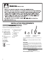
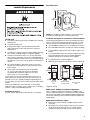
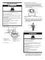
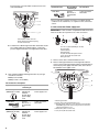
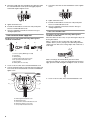
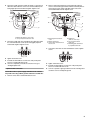
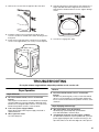
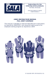
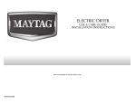
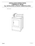
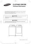
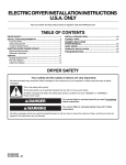
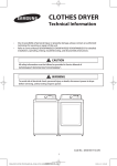
ELECTRIC DRYER INSTALLATION INSTRUCTIONS
U.S.A. ONLY
Para una version de estas instrucciones en español, visite www.Whirlpool.com
TABLE OF CONTENTS
TABLE OF CONTENTS ..................................................................1
DRYER SAFETY..............................................................................1
INSTALLATION REQUIREMENTS ................................................2
Tools and Parts ............................................................................2
Optional Equipment .....................................................................2
Location Requirements................................................................3
ELECTRIC DRYER POWER HOOKUP .........................................4
Electrical Requirements ...............................................................4
Electrical Connection ...................................................................5
VENTING........................................................................................10
Venting Requirements................................................................10
Plan Vent System .......................................................................11
Install Vent System.....................................................................12
INSTALL LEVELING LEGS...........................................................12
CONNECT VENT...........................................................................12
CONNECT INLET HOSE (STEAM MODELS)..............................13
LEVEL DRYER ..............................................................................13
COMPLETE INSTALLATION .......................................................13
Reverse Door Swing...................................................................14
TROUBLESHOOTING .................................................................15
Dryer Operation ..........................................................................15
Dryer Results ..............................................................................16
DRYER SAFETY
Your safety and the safety of others are very important.
We have provided many important safety messages in this manual and on your appliance. Always read and obey all safety
messages.
This is the safety alert symbol.
This symbol alerts you to potential hazards that can kill or hurt you and others.
All safety messages will follow the safety alert symbol and either the word “DANGER” or “WARNING.”
These words mean:
DANGER
WARNING
You can be killed or seriously injured if you don't immediately
follow instructions.
You can be killed or seriously injured if you don't follow
instructions.
All safety messages will tell you what the potential hazard is, tell you how to reduce the chance of injury, and tell you what can
happen if the instructions are not followed.
W10267633A
INSTALLATION REQUIREMENTS
Steam Models
Tools and Parts
Gather the required tools and parts before starting installation. Read
and follow the instructions provided with any tools listed here.
■
Flat-blade screwdriver
■
#2 Phillips screwdriver
■
Adjustable wrench that
opens to 1" (25 mm) or
hex-head socket wrench
(for adjusting dryer feet)
■
Level
■
Wire stripper (direct wire
installations)
■
Vent clamps
Parts supplied:
■
Caulking gun and compound
(for installing new exhaust
vent)
■
Tin snips (new vent
installations)
■
¼" nut driver
(recommended)
■
Tape measure
■
Pliers
A
B
A. Leveling legs (4)
B. “Y” connector
C. Short inlet hose
C
D
E
D. Inlet hose with right-angle
connector
E. Rubber washer
Remove parts package from dryer drum. Check that all parts are
included.
NOTE: Do not use leveling legs supplied with dryer if installing
on a pedestal.
Non-Steam Models
Parts needed
4 Leveling legs
Check local codes. Check existing electrical supply and venting.
See “Electrical Requirements” and “Venting Requirements” before
purchasing parts.
Mobile home installations require metal exhaust system hardware
available for purchase from the dealer from whom you purchased
your dryer. For further information, please refer to the “Assistance
or Service” section in your Use and Care Guide.
Optional Equipment
Refer to your Use and Care guide for information about the
accessories available for your dryer.
2
Location Requirements
Dryer Dimensions
431/2"
(1105 mm)
291/4"
(743 mm)
29"
(737 mm)
221/4"
(565 mm)
NOTE: Most installations require minimum 5" (127 mm) clearance
for exhaust vent with elbow. See “Venting Requirements.”
You will need
Installation spacing for recessed area or closet installation
■
A location that allows proper exhaust installation. See “Venting
Requirements.”
■
A separate 30-amp circuit.
■
If using a power supply cord, a grounded electrical outlet
within 2 ft (610 mm) of either side of dryer. See “Electrical
Requirements.”
The following spacing dimensions are recommended for this dryer.
Dryer has been tested for spacing of 0" (0 mm) clearance on sides
and rear. Consider recommended spacing for following reasons:
■ Consider additional spacing for ease of installation and service.
■
A sturdy floor to support total dryer weight of 200 lbs. (90.7 kg).
Also consider combined weight of a companion appliance.
■
A level floor with maximum slope of 1" (25 mm) under entire
dryer. If slope is greater than 1" (25 mm), install Extended Dryer
Feet Kit, Part Number 279810. Clothes may not tumble properly
and automatic sensor cycles may not operate correctly if dryer is
not level.
■
■
■
May need additional clearance for wall, door, and floor moldings.
■
Consider additional spacing on all sides of dryer to reduce noise
transfer.
■
For closet installation, with a door, minimum ventilation openings
in the top and bottom of the door are required. Equivalent
ventilation openings in louvered doors are acceptable.
■
Consider spacing for companion appliance.
■
Additional space required for rear exhaust of dryer to right or left.
For a garage installation, place dryer at least 18" (457 mm)
above floor. If using a pedestal, you will need 18" (457 mm) to
bottom of dryer.
Steam models only: Cold water faucets located within
4 ft. (1.2 m) of dryer, and water pressure of 20-100 psi
(137.9-689.6 kPa). Cold water supply may come from
washer using “Y” connector provided.
Do not operate your dryer at temperatures below 45ºF (7ºC). At
lower temperatures, the dryer may not shut off at the end of an
automatic sensor cycle, possibly resulting in longer drying times.
Do not install or store dryer where it will be exposed to water and/or
weather.
Check code requirements. Some codes limit, or do not permit,
installation of dryer in garages, closets, mobile homes, or sleeping
quarters. Contact your local building inspector.
14" máx.*
(356 mm)
18"*
(457 mm)
48" 2*
(310 cm2)
3"*
(76 mm)
3"*
(76 mm)
24" 2*
(155 cm2)
1"
(25 mm)
29"
(737 mm)
Recessed
area
1"
(25 mm)
291/4"
(743 mm)
Side view- closet
or confined area
5"
(127 mm)
Closet door with
vents
*Required spacing
Mobile home - Additional installation requirements
Installation clearances
Location must be large enough to allow dryer door to open fully.
Dryer is suitable for mobile home installations. Installation must
conform to Manufactured Home Construction and Safety Standard,
Title 24 CFR, Part 3280 (formerly Federal Standard for Mobile Home
Construction and Safety, Title 24, HUD Part 280) or Standard CAN/
CSA-Z240 MH.
Mobile home installations require:
■
Metal exhaust system hardware, available for purchase from
your dealer.
■
Special provisions must be made in mobile homes to introduce
outside air into dryer. Openings (such as a nearby window)
should be at least twice as large as dryer exhaust opening.
3
ELECTRIC DRYER POWER HOOKUP
Electrical Requirements
It is your responsibility
■
To contact a qualified electrical installer.
■
To be sure that the electrical connection is adequate and
in conformance with the National Electrical Code, ANSI/NFPA
70-latest edition and all local codes and ordinances.
The National Electrical Code requires a 4-wire power supply
connection for homes built after 1996, dryer circuits involved in
remodeling after 1996, and all mobile home installations.
A copy of the above code standards can be obtained from:
National Fire Protection Association, One Batterymarch Park,
Quincy, MA 02269.
■
To supply the required 3 or 4 wire, single phase, 120/240 volt,
60 Hz., AC only electrical supply (or 3 or 4 wire, 120/208 volt
electrical supply, if specified on the serial/rating plate) on
a separate 30-amp circuit, fused on both sides of the line.
A time-delay fuse or circuit breaker is recommended. Connect
to an individual branch circuit. Do not have a fuse in the neutral
or grounding circuit.
■
Do not use an extension cord.
■
If codes permit and a separate ground wire is used, it is
recommended that a qualified electrician determine that
the ground path is adequate.
Electrical Connection
To properly install your dryer, you must determine the type of
electrical connection you will be using and follow the instructions
provided for it here.
■ This dryer is manufactured ready to install with a 3-wire
electrical supply connection. The neutral ground conductor
is permanently connected to the neutral conductor (white wire)
within the dryer. If the dryer is installed with a 4-wire electrical
supply connection, the neutral ground conductor must be
removed from the external ground connector (green screw),
and secured under the neutral terminal (center or white wire)
of the terminal block. When the neutral ground conductor
is secured under the neutral terminal (center or white wire)
of the terminal block, the dryer cabinet is isolated from
the neutral conductor.
■
If local codes do not permit the connection of a neutral ground
wire to the neutral wire, see “Optional 3-wire connection”
section.
■
A 4-wire power supply connection must be used when
the appliance is installed in a location where grounding through
the neutral conductor is prohibited. Grounding through
the neutral is prohibited for (1) new branch-circuit installations,
(2) mobile homes, (3) recreational vehicles, and (4) areas where
local codes prohibit grounding through the neutral conductors.
If using a power supply cord:
Use a UL listed power supply cord kit marked for use with clothes
dryers. The kit should contain:
■ A UL listed 30-amp power supply cord, rated 120/240 volt
minimum. The cord should be type SRD or SRDT and be at least
4 ft. (1.22 m) long. The wires that connect to the dryer must end
in ring terminals or spade terminals with upturned ends.
■
4
A UL listed strain relief.
If your outlet looks like this:
Then choose a 4-wire power supply cord
with ring or spade terminals and UL listed strain
relief. The 4-wire power supply cord, at least 4 ft.
(1.22 m) long, must have four 10-gauge copper
wires and match a 4-wire receptacle of NEMA
Type 14-30R. The ground wire (ground
4-wire receptacle
conductor) may be either green or bare.
(14-30R)
The neutral conductor must be identified
by a white cover.
If your outlet looks like this:
Then choose a 3-wire power supply cord with
ring or spade terminals and UL listed strain relief.
The 3-wire power supply cord, at least 4 ft
(1.22 m) long, must have three 10-gauge copper
wires and match a 3-wire receptacle of NEMA
Type 10-30R.
3-wire receptacle
(10-30R)
If connecting by direct wire:
Power supply cable must match power supply (4-wire or 3-wire)
and be:
■ Flexible armored cable or nonmetallic sheathed copper cable
(with ground wire), protected with flexible metallic conduit. All
current-carrying wires must be insulated.
■
10-gauge solid copper wire (do not use aluminum) at least
5 ft. (1.52 m) long.
Style 1: Power supply cord strain relief
Electrical Connection
■
WARNING
Remove screws from a 3/4" (19 mm) UL listed strain relief
(UL marking on strain relief). Put tabs of the two clamp
sections into hole below terminal block opening so that
one tab is pointing up and the other is pointing down, and
hold in place. Tighten strain relief screws enough to hold two
clamp sections together.
A
B
Fire Hazard
C
D
Use a new UL listed 30 amp power supply cord.
Use a UL listed strain relief.
Disconnect power before making electrical connections.
Connect neutral wire (white or center wire) to center
terminal (silver).
Ground wire (green or bare wire) must be connected to
green ground connector.
A. Strain relief tab pointing up
B. Hole below terminal block
opening
■
Connect remaining 2 supply wires to remaining
2 terminals (gold).
C. Clamp section
D. Strain relief tab pointing down
Put power supply cord through strain relief. Be sure that wire
insulation on power supply cord is inside strain relief. Strain
relief should have a tight fit with the dryer cabinet and be in
a horizontal position. Do not further tighten strain relief
screws at this point.
Securely tighten all electrical connections.
Failure to do so can result in death, fire, or
electrical shock.
1. Disconnect Power.
2. Remove hold-down screw and terminal block cover.
D
AB
C
Style 2: Direct wire strain relief
WARNING
E
F
A. Terminal block cover
B. Hold-down screw
C. External ground conductor
screw
3. Install strain relief.
D. Center, silver-colored terminal
block screw
E. Neutral ground wire
F. Hole below terminal block
opening
Fire Hazard
Use 10 gauge solid copper wire.
Use a UL listed strain relief.
Disconnect power before making electrical connections.
Connect neutral wire (white or center wire) to center
terminal (silver).
Ground wire (green or bare wire) must be connected to
green ground connector.
Connect remaining 2 supply wires to remaining
2 terminals (gold).
Securely tighten all electrical connections.
Failure to do so can result in death, fire, or
electrical shock.
■
Unscrew removable conduit connector and any screws from
a 3/4" (19 mm) UL listed strain relief (UL marking on strain
relief). Put threaded section of strain relief through hole
below terminal block opening. Reaching inside terminal
5
block opening, screw removable conduit connector onto
strain relief threads.
If your home has:
And you will be
connecting to:
Go to Section
3-wire direct
A fused
disconnect or
circuit breaker
box*
3-wire connection:
Direct Wire
(89 mm)
A
B
*If local codes do not permit connection of a cabinet-ground
conductor to the neutral wire, see “Optional 3-wire connection”
section.
4-wire connection: Power supply cord
C
IMPORTANT: A 4-wire connection is required for mobile homes and
where local codes do not permit use of 3-wire connections.
F
B
A
A. Removable conduit connector
B. Hole below terminal block opening
C. Strain relief threads
C
■
Put direct wire cable through strain relief. Strain relief should
have a tight fit with dryer cabinet and be in a horizontal
position. Tighten strain relief screw against direct wire cable.
D
E
G
A. 4-wire receptacle (NEMA type 14-30R)
B. 4-prong plug
C. Ground prong
D. Neutral prong
E. Spade terminals with upturned ends
F. 3/4" (19 mm) UL listed strain relief
G. Ring terminals
1. Remove center, silver-colored terminal block screw.
2. Remove neutral ground wire from external ground conductor
screw. Connect neutral ground wire and the neutral wire (white or
center wire) of power supply cord under center, silver-colored
terminal block screw. Tighten screw.
4. Now complete installation following instructions for your type
of electrical connection:
4-wire (recommended)
B
C
3-wire (if 4-wire is not available)
D
Electrical Connection Options
A
If your home has:
And you will be
connecting to:
Go to Section
4-wire receptacle
(NEMA Type 14-30R)
A UL listed,
120/240-volt
minimum,
30-amp, dryer
power supply
cord*
4-wire connection:
Power supply cord
4-wire direct
A fused
disconnect or
circuit breaker
box*
4-wire connection:
Direct Wire
A UL listed,
120/240-volt
minimum,
30-amp, dryer
power supply
cord*
3-wire connection:
Power supply cord
5"
(127 mm)
3-wire receptacle
(NEMA type 10-30R)
6
E
A. Neutral ground wire.
B. Center, silver-colored terminal block screw
C. External ground conductor screw - Dotted line shows position
of NEUTRAL ground wire before being moved to center silvercolored terminal block screw
D. Neutral wire (white or center wire)
E. 3/4" (19 mm) UL listed strain relief
When connecting to the terminal block, place the hooked end of the
wire under the screw of the terminal block (hook facing right),
squeeze hooked end together and tighten screw, as shown.
r wire)
sc
3. Connect ground wire (green or bare) of power supply cord to
external ground conductor screw. Tighten screw.
1. Remove center, silver-colored terminal block screw.
2. Remove neutral ground wire from external ground conductor
screw. Connect neutral ground wire and place the hooked end
(hook facing right) of the neutral wire (white or center wire) of direct
wire cable under the center screw of the terminal block. Squeeze
hooked ends together. Tighten screw.
C
A. External ground conductor screw
B. Neutral ground wire
C. Ground wire (green or bare) of power supply cord
D. 3/4" (19 mm) UL listed strain relief
E. Center, silver-colored terminal block screw
F. Neutral wire (white or center wire)
B
4. Connect the other wires to outer terminal block screws. Tighten
screws.
A
D
E
5. Tighten strain relief screws.
6. Insert tab of terminal block cover into slot of dryer rear panel.
Secure cover with hold-down screw.
7. You have completed your electrical connection. Now go to
“Venting Requirements.”
4-wire connection: Direct wire
IMPORTANT: A 4-wire connection is required for mobile homes and
where local codes do not permit the use of 3-wire connections.
Direct wire cable must have 5 ft. (1.52 m) of extra length so dryer can
be moved if needed.
Strip 5" (127 mm) of outer covering from end of cable, leaving bare
ground wire at 5" (127 mm). Cut 11/2" (38 mm) from 3 remaining
wires. Strip insulation back 1" (25 mm). Shape ends of wires into a
hook shape.
A. Neutral ground wire.
B. External ground conductor screw - Dotted line shows
position of NEUTRAL ground wire before being moved to
center, silver-colored terminal block screw
C. Center, silver-colored terminal block screw
D. Neutral wire (white or center wire)
E. 3/4" (19 mm) UL listed strain relief
3. Connect ground wire (green or bare) of direct wire cable to
external ground conductor screw. Tighten screw.
E
A
B
C
F
1" )
mm
(25
D
5"
(127 m
m)
A. External ground conductor screw
B. Neutral ground wire
C. Ground wire (green or bare) of power supply cable
D. 3/4" (19 mm) UL listed strain relief
E. Center, silver-colored terminal block screw
F. Neutral wire (white or center wire)
7
4. Place the hooked ends of the other direct wire cable wires under
the outer terminal block screws (hooks facing right). Squeeze
hooked ends together. Tighten screws.
5. Tighten strain relief screw.
6. Insert tab of terminal block cover into slot of dryer rear panel.
Secure cover with hold-down screw.
7. You have completed your electrical connection. Now go to
“Venting Requirements.”
Use where local codes permit connecting cabinet-ground
conductor to neutral wire.
D
4. Tighten strain relief screws.
5. Insert tab of terminal block cover into slot of dryer rear panel.
Secure cover with hold-down screw.
6. You have completed your electrical connection. Now go to
“Venting Requirements.”
3-wire connection: Direct wire
Use where local codes permit connecting cabinet-ground
conductor to neutral wire.
Direct wire cable must have 5 ft. (1.52 m) of extra length so dryer can
be moved if needed.
Strip 31/2" (89 mm) of outer covering from end of cable. Strip
insulation back 1" (25 mm). If using 3-wire cable with ground wire,
cut bare wire even with outer covering. Shape ends of wires into a
hook shape.
3-wire connection: Power supply cord
B
3. Connect the other wires to outer terminal block screws. Tighten
screws.
E
A
1"
C
F
G
A. 3-wire receptacle (NEMA type 10-30R)
B. 3-wire plug
C. Neutral prong
D. Spade terminals with up turned ends
E.3/4" (19 mm) UL listed strain relief
F. Ring terminals
G. Neutral (white or center wire)
(25
)
mm
3½"
m)
(89 m
When connecting to the terminal block, place the hooked
end of the wire under the screw of the terminal block (hook facing
right), squeeze hooked end together and tighten screw, as shown.
1. Loosen or remove center, silver-colored terminal block screw.
2. Connect neutral wire (white or center wire) of power supply cord
to the center, silver-colored terminal screw of the terminal block.
Tighten screw.
1. Loosen or remove center, silver-colored terminal block screw.
A
C
B
D
E
A. External ground conductor screw
B. Neutral ground wire
C. Center, silver-colored terminal block screw
D. Neutral wire (white or center wire)
E. 3/4" (19 mm) UL listed strain relief
8
2. Place the hooked end of the neutral wire (white or center wire) of
direct wire cable under the center screw of terminal block (hook
facing right). Squeeze hooked end together. Tighten screw.
2. Remove neutral ground wire from external ground conductor
screw. Connect neutral ground wire and the neutral wire (white or
center wire) of power supply cord/cable under center, silvercolored terminal block screw. Tighten screw.
C
A
A
B
D
C
B
D
E
E
F
D. Neutral wire (white or center wire)
E. 3/4" (19 mm) UL listed strain relief
3. Place the hooked ends of the other direct wire cable wires under
the outer terminal block screws (hooks facing right). Squeeze
hooked ends together. Tighten screws.
A. External ground conductor
screw
B. Neutral ground wire
C. Center, silver-colored terminal
block screw
D. Neutral wire
(white or center wire)
E. 3/4" (19 mm) UL listed
strain relief
F. Grounding path determined
by a qualified electrician
3. Connect the other wires to outer terminal block screws. Tighten
screws.
4. Tighten strain relief screw.
5. Insert tab of terminal block cover into slot of dryer rear panel.
Secure cover with hold-down screw.
6. You have completed your electrical connection. Now go to
“Venting Requirements.”
Optional 3-wire connection
4. Tighten strain relief screws.
5. Insert tab of terminal block cover into slot of dryer rear panel.
Secure cover with hold-down screw.
6. Connect a separate copper ground wire from the external ground
conductor screw to an adequate ground.
Use for direct wire or power supply cord where local codes do
not permit connecting cabinet-ground conductor to neutral wire.
1. Remove center, silver-colored terminal block screw.
9
VENTING
Venting Requirements
WARNING
Fire Hazard
Use a heavy metal vent.
Flexible metal vent
■ Flexible metal vents are acceptable only if accessible
for cleaning.
■
Flexible metal vent must be fully extended and supported when
the dryer is in its final location.
■
Remove excess flexible metal vent to avoid sagging and kinking
that may result in reduced airflow and poor performance.
■
Do not install flexible metal vent in enclosed walls, ceilings,
or floors.
■
The total length of flexible metal vent should not exceed 7¾ ft.
(2.4 m).
Elbows
45° elbows provide better airflow than 90° elbows.
Do not use a plastic vent.
Do not use a metal foil vent.
Failure to follow these instructions can result in death
or fire.
WARNING: To reduce the risk of fire, this dryer MUST BE
EXHAUSTED OUTDOORS.
IMPORTANT: Observe all governing codes and ordinances.
The dryer exhaust must not be connected into any gas vent,
chimney, wall, ceiling, attic, crawlspace, or a concealed space
of a building. Only rigid or flexible metal vent shall be used for
exhausting.
Good
Clamps
■ Use clamps to seal all joints.
■
If using an existing vent system
■
Clean lint from the entire length of the system and make sure
exhaust hood is not plugged with lint.
■
Replace any plastic or metal foil vent with rigid or flexible heavy
metal vent.
■
Review vent system chart. Modify existing vent system if
necessary to achieve the best drying performance.
Exhaust vent must not be connected or secured with screws or
other fastening devices that extend into the interior of the duct
and catch lint. Do not use duct tape.
Clamp
Exhaust
If this is a new vent system
B
Vent material
■
Use a heavy metal vent. Do not use plastic or metal foil vent.
■
4" (102 mm) heavy metal exhaust vent and clamps must be
used.
4"
(102 mm)
A
4"
(102 mm)
4"
(102 mm)
4"
102 mm
Recommended:
A. Louvered hood style
B. Box hood style
4" (102 mm) heavy metal exhaust vent
Vent products can be purchased from your dealer or by calling
Whirlpool Service. For more information, see the “Assistance or
Service” section in your Use and Care Guide.
Rigid metal vent
■ For best drying performance, rigid metal vents are
recommended.
■
10
Rigid metal vent is recommended to avoid crushing and kinking.
Better
C
2½"
(64 mm)
Acceptable:
C. Angled hood style
■
An exhaust hood should cap the vent to keep rodents and
insects from entering the home.
■
Exhaust hood must be at least 12" (305 mm) from the ground or
any object that may be in the path of the exhaust (such as
flowers, rocks or bushes, snow line, etc.).
■
Do not use an exhaust hood with a magnetic latch.
Improper venting can cause moisture and lint to collect
indoors, which may result in:
Moisture damage to woodwork, furniture, paint, wallpaper,
carpets, etc.
Housecleaning problems and health problems.
A
B
C
A. Standard rear offset exhaust installation
B. Left or right side exhaust installation
C. Bottom exhaust installation
Plan Vent System
Choose your exhaust installation type
Alternate installations for close clearances
Recommended exhaust installations
Typical installations vent the dryer from the rear of the dryer.
B
Venting systems come in many varieties. Select the type best for
your installation. Two close-clearance installations are shown. Refer
to the manufacturer’s instructions.
C
D
E
A
F
G
B
A. Over-the-top installation (also available with one offset elbow)
B. Periscope installation
H
A. Dryer
B. Elbow
C. Wall
D. Exhaust hood
E. Clamps
F. Rigid metal or flexible metal vent
G. Vent length necessary to connect elbows
H. Exhaust outlet
NOTE: The following kits for close clearance alternate installations
are available for purchase. Please see the “Assistance or Service”
section in your Use and Care Guide to order.
■ Over-the-Top Installation:
Part Number 4396028
Optional exhaust installations
■
Periscope Installation (For use with dryer vent to wall vent
mismatch):
Part Number 4396037 - 0" (0 mm) to 18" (457 mm) mismatch
Part Number 4396011 - 18" (457 mm) to 29" (737 mm)
mismatch
Part Number 4396014 - 29" (737 mm) to 50" (1.27 m) mismatch
Special provisions for mobile home installations
The exhaust vent must be securely fastened to a noncombustible
portion of the mobile home structure and must not terminate
beneath the mobile home. Terminate the exhaust vent outside.
■
Exhaust Cover Kit (to cover unused exhaust holes):
Part Number W10186596 - all models
This dryer can be converted to exhaust out the right side, left side or
through the bottom. If you prefer, you may contact your local dealer
to have the dryer converted.
11
Determine vent path
INSTALL LEVELING LEGS
■
Select the route that will provide the straightest and most direct
path outdoors.
■
Plan the installation to use the fewest number of elbows and
turns.
■
When using elbows or making turns, allow as much room as
possible.
Use two or more people to move and install dryer.
■
Bend vent gradually to avoid kinking.
Failure to do so can result in back or other injury.
■
Use the fewest 90° turns possible.
Determine vent length and elbows needed for best
drying performance
■
Use the following vent system chart to determine type of vent
material and hood combinations acceptable to use.
WARNING
Excessive Weight Hazard
1. To avoid damaging the floor, use a large flat piece of cardboard
from the dryer carton. Place cardboard under the entire back
edge of the dryer.
2. Firmly grasp the body of the dryer (not the console panel). Gently
lay the dryer on the cardboard. See illustration.
NOTE: Do not use vent runs longer than those specified in the
Vent system chart.
Exhaust systems longer than those specified will:
■
Shorten the life of the dryer.
■
Reduce performance, resulting in longer drying times and
increased energy usage.
The vent system chart provides venting requirements that will help
to achieve the best drying performance.
3. Examine the leveling legs. Find the diamond marking.
Vent system chart
NOTE: Side and bottom exhaust installations have a 90º turn inside
the dryer. To determine maximum exhaust length, add one 90º turn
to the chart.
Number 90º
elbows
Type of vent
Box /louvered
hoods
Angled
hoods
0
Rigid metal
64 ft. (20 m)
58ft. (17.7 m)
1
Rigid metal
54 ft. (16.5 m)
48 ft. (14.6 m)
2
Rigid metal
44 ft. (13.4 m)
38 ft. (11.6 m)
3
Rigid metal
35 ft. (10.7 m)
29 ft. (8.8 m)
4
Rigid metal
27 ft. (8.2 m)
21 ft. (6.4 m)
Install Vent System
1. Install exhaust hood. Use caulking compound to seal exterior wall
opening around exhaust hood.
2. Connect vent to exhaust hood. Vent must fit inside exhaust hood.
Secure vent to exhaust hood with 4" (102 mm) clamp.
3. Run vent to dryer location. Use the straightest path possible. See
“Determine vent path” in “Plan Vent System.” Avoid 90º turns.
Use clamps to seal all joints. Do not use duct tape, screws or
other fastening devices that extend into the interior of the vent to
secure vent, which can catch lint.
4. Screw the legs into the leg holes by hand. Use a wrench to finish
turning the legs until the diamond marking is no longer visible.
5. Place a carton corner post from dryer packaging under each of
the 2 dryer back corners. Stand the dryer up. Slide the dryer on
the corner posts until it is close to its final location. Leave enough
room to connect the exhaust vent.
CONNECT VENT
1. Using a 4" (102 mm) clamp, connect vent to exhaust outlet in
dryer. If connecting to existing vent, make sure the vent is clean.
The dryer vent must fit over the dryer exhaust outlet and inside the
exhaust hood. Check that the vent is secured to exhaust hood
with a 4" (102 mm) clamp.
2. Move dryer into its final location. Do not crush or kink vent.
3. Once the exhaust vent connection is made, remove the corner
posts and cardboard.
CONNECT INLET HOSE
(STEAM MODELS)
The dryer must be connected to the cold water faucet using the new
inlet hoses. Do not use old hoses.
1. Turn cold water faucet off and remove washer inlet hose.
2. Remove old rubber washer from inlet hose and replace with new
rubber washer provided. If space permits, attach the brass female
end of the “Y” connector to the cold water faucet.
NOTE: If “Y” connector can be attached directly to cold water
faucet, go to Step 6. If “Y” connector cannot be attached
directly to the cold water faucet, the short hose must be used.
Continue with Step 3.
3. Attach short hose to cold water faucet. Screw on coupling by
hand until it is seated on faucet.
12
4. Using pliers, tighten the couplings with an additional two-thirds
turn.
LEVEL DRYER
Check the levelness of the dryer by first placing a level on the top
of the dryer near the console.
NOTE: Do not overtighten. Damage to the coupling can result.
5. Attach “Y” connector to brass male end of small hose. Screw on
coupling by hand until it is seated on connector.
6. Attach straight end of long hose to “Y” connector.
7. Attach washer cold inlet hose to other end of “Y” connector.
Screw on coupling by hand until it is seated on connector.
8. Using pliers, tighten the couplings an additional two-thirds turn.
Then, by placing a level in the crease on the side of the dryer
between the top of the dryer and the dryer cabinet, check
the levelness from front to back.
A
If the dryer is not level, prop up the dryer using a wood block. Use a
wrench to adjust the legs up or down and check again for levelness.
A. Inlet to cold water
NOTE: Do not overtighten. Damage to the coupling can result.
9. Attach angled end of long hose to fill valve at bottom of dryer
back panel. Screw on coupling by hand until it is seated on fill
valve connector.
10. Using pliers, tighten the coupling an additional two-thirds turn.
COMPLETE INSTALLATION
NOTE: Do not overtighten. Damage to the coupling can result.
11. Check that the water faucets are on.
12. Check for leaks around “Y” connector, faucet, and hoses.
1. Check that all parts are now installed. If there is an extra part,
go back through the steps to see which step was skipped.
2. Check that you have all of your tools.
3. Dispose of/recycle all packaging materials.
4. Check the dryer’s final location. Be sure the vent is not crushed
or kinked.
5. Check that the dryer is level. See “Level Dryer.”
6. Remove the blue film on the console and any tape remaining on
the dryer.
7. Wipe the dryer drum interior thoroughly with a damp cloth to
remove any dust.
8. Read “Dryer Use” in your Use and Care Guide.
9. For power supply cord installation, plug into a grounded outlet.
For direct wire installation, turn on power.
Steam Models Only:
10. Be sure the water faucets are on.
11. Check for leaks around “Y” connector, faucet, and hoses.
12. If you live in a hard water area, use of a water softener is
recommended to control the buildup of scale through the water
system in the dryer. Over time, the buildup of lime scale may clog
different parts of the water system, which will reduce product
performance. Excessive scale buildup may lead to the need for
certain part replacement or repair.
13
All Models:
13. Select a Timed Dry heated cycle, and start the dryer. Do not select
the Air Only Temperature setting.
If the dryer will not start, check the following:
5. Remove the 4 plastic plugs located outside the dryer door
opening.
■
Controls are set in a running or “On” position.
Start button has been pushed firmly.
■ Dryer is plugged into an outlet and/or electrical supply
is connected.
■ Household fuse is intact and tight, or circuit breaker has
not tripped.
■ Dryer door is closed.
This dryer automatically runs an installation diagnostic routine at the
start of its first cycle.
If you receive an L2 code, there may be a problem with your
home power supply keeping the dryer’s heater from turning on.
See “Troubleshooting.”
If you receive an AF code, your dryer vent may be crushed or
blocked. See “Troubleshooting.”
NOTE: You may notice an odor when the dryer is first heated.
This odor is common when the heating element is first used.
The odor will go away.
■
REVERSE DOOR SWING
You can change your door swing from a right-side opening to a
left-side opening, if desired.
1. Place a towel or soft cloth on top of dryer or work space to
avoid damaging the surface.
Remove the door assembly
1. Open the dryer door.
2. Remove the bottom screw from each of the 2 hinges that
attach dryer door to front panel of dryer.
3. Loosen the top screw from each of the 2 hinges in Step 2.
6. Install 4 plastic plugs into screw holes in the dryer left where
the hinges were removed in Step 4.
Reverse the strike
1. Remove the door strike from the dryer door opening.
2. Remove the cosmetic screw opposite the door strike.
A
B
A. Door strike
B. Cosmetic screw
A
B
3. Reinstall the door strike and cosmetic screw on the opposite
side of the dryer door opening from where they were
removed.
NOTE: Door strike and plugs must be on the same side of the
dryer door opening.
Reinstall the door
A
B
A. Loosen these screws.
B. Remove these screws.
4. Remove the dryer door and the hinges by lifting upward on
the door. Lay the door on a flat, protected surface, with the
inside of the door facing up. Remove remaining 2 loose
screws from dryer front panel.
14
1. Remove the 4 screws and 2 hinges from the dryer door.
2. Replace the 4 screws in the same holes.
3. Remove the 4 screws from the opposite side of the door.
4. Install the 2 hinges to the front panel of the dryer using
4 screws. Use the non-slotted side to attach the hinge to the
front panel.
5. Install screws in top hinge holes in the door. Do not tighten
screws. Leave approximately 1/4" (5 mm) of screw exposed.
6. Hang door by placing screw heads into top slotted holes of
hinges and slide door down. Align bottom screw holes in
hinge and door. Install two bottom screws. Tighten all hinge
screws.
7. Close door to engage door strike.
TROUBLESHOOTING
First try the solutions suggested here and possibly avoid the cost of a service call...
No heat
Dryer Operation
Dryer will not run
■
■
Has a household fuse blown, or has a circuit breaker
tripped?
There may be 2 household fuses or circuit breakers for the dryer.
Check that both fuses are intact and tight, or that both circuit
breakers have not tripped. Replace the fuse or reset the circuit
breaker. If the problem continues, call an electrician.
Has a household fuse blown, or has a circuit breaker
tripped?
The drum may be turning, but you may not have heat. Electric
dryers use 2 household fuses or circuit breakers. Replace the
fuse or reset the circuit breaker. If the problem continues, call an
electrician.
Dryer displaying code message
■
Is the correct power supply available?
Electric dryers require 240-volt power supply. Check with a
qualified electrician.
■
“PF” (power failure), check the following:
Was the drying cycle interrupted by a power failure?
Press and hold START to restart the dryer.
■
Was a regular fuse used?
Use a time-delay fuse.
■
“L2” Diagnostic Code (low or no line voltage condition):
The drum will turn, but there may be a problem with your home
power supply keeping the dryer's heater from turning on. The
dryer will continue to run when this diagnostic code is present.
15
Press any key to clear the code from the display and return to
the estimated time remaining.
Try the following:
Check to see if a household fuse has blown or circuit breaker
has tripped. Electric dryers use two household fuses or
breakers. Replace the fuse or reset the circuit breaker.
Confirm the power cord is properly installed. Refer to “Electrical
Connection” for details.
■
■
Select a Timed Dry heated cycle, and restart the dryer.
If the message persists, consult a qualified electrician.
■
“AF” (low airflow condition):
The dryer will continue to run when this diagnostic code is
present. Press any key to clear the code from the display and
return to the estimated time remaining.
■
Try the following:
Clean lint screen.
■
Check to see if the vent run from the dryer to the wall is
crushed or kinked.
■
Confirm the vent run from the dryer to the wall is free of lint
and debris.
■
Confirm the exterior vent exhaust hood is free of lint and
debris.
■
Confirm your vent system falls within the recommended run
length and number of elbows for the type of vent you are
using. Refer to “Plan Vent System” for details.
■
Select a Timed Dry heated cycle, and restart the dryer.
If the message persists, have your entire home venting run
cleaned.
■
■
Is the dryer located in a room with temperature below 45ºF
(7ºC)?
Proper operation of dryer cycles requires temperatures above
45ºF (7ºC).
■
Is the dryer located in a closet?
Closet doors must have ventilation openings at the top and
bottom of the door. The front of the dryer requires a minimum of
1" (25 mm) of airspace, and, for most installations, the rear of the
dryer requires 5" (127 mm). See the Installation Instructions.
“E” Variable (E1, E2, E3) service codes:
Call for service.
Dryer Results
Clothes are not drying satisfactorily, drying times are too
long, or load is too hot
■
■
outside exhaust hood to check air movement. If you do not feel
air movement, clean exhaust system of lint or replace exhaust
vent with heavy metal or flexible metal vent. See the Installation
Instructions.
Are fabric softener sheets blocking the grille?
Use only one fabric softener sheet, and use it only once.
Is the exhaust vent the correct length?
Check that the exhaust vent is not too long or has too many
turns. Long venting will increase drying times. See the
Installation Instructions.
Is the exhaust vent diameter the correct size?
Use 4" (102 mm) diameter vent material.
Is the lint screen clogged with lint?
Lint screen should be cleaned before each load.
WARNING
Fire Hazard
Use a heavy metal vent.
Do not use a plastic vent.
Do not use a metal foil vent.
Failure to follow these instructions can result in death
or fire.
■
Is the exhaust vent or outside exhaust hood clogged with
lint, restricting air movement?
Run the dryer for 5-10 minutes. Hold your hand under the
W10267633A
© 2009 Whirlpool Corporation.
All rights reserved.
11/09
Printed in U.S.A.