1
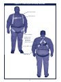
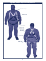
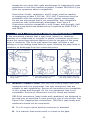
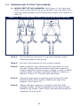
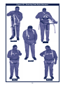
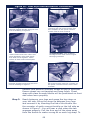
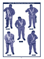
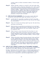
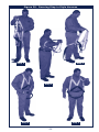
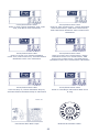
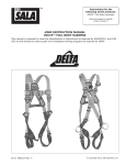
Instructions for the
following series products:
Full Body Harnesses
(See back pages for specific
model numbers.)
User Instruction Manual
Full Body Harness
This manual is intended to meet the Manufacturer’s Instructions
as required by ANSIZ359.1 and should be used as part of an
employee training program as required by OSHA
© Copyright 2007, DB Industries, Inc.
Figure 1 - WorkVest Style Full Body Harness
Shoulder Strap
Chest Strap
Leg
Strap
Attachment
Element for
Fall Arrest
(D-ring or
Web Loop)
Labels and
RFID Tag
Figure 2 - Vest Style Full Body Harness
Shoulder Strap
Chest Strap
Leg Strap
Attachment
Element for
Fall Arrest
(D-ring or
Web Loop)
D-ring Pad
Labels and
RFID Tag
Figure 3 - Cross-over Style Full Body Harness
Shoulder Strap
Front Attachment Element
(D-ring or Web Loop)
Leg Strap
Attachment
Element for
Fall Arrest
(D-ring or
Web Loop)
D-ring Pad
Labels and
RFID Tag
Figure 4 - Step-in Style Full Body Harness
Shoulder Strap
Front D-ring
Leg Strap
Attachment
Element for
Fall Arrest
(D-ring or
Web Loop)
D-ring Pad
Labels and
RFID Tag
WARNING: This product is part of a personal fall arrest, restraint,
work positioning, personnel riding, climbing, or rescue system. The
user must follow the manufacturer’s instructions for each component
of the system. These instructions must be provided to the user of this
equipment. The user must read and understand these instructions
before using this equipment. Manufacturer’s instructions must be
followed for proper use and maintenance of this equipment. Alterations
or misuse of this product or failure to follow instructions may result in
serious injury or death.
IMPORTANT: If you have questions on the use, care, or suitability of
this equipment for your application, contact DBI‑SALA.
IMPORTANT: Before using this equipment, record the product
identification information from the ID label in the inspection and
maintenance log in section 9.0 of this manual.
DESCRIPTIONS
Work Vest Style Full Body Harness: See Figure 1.
Vest Style Full Body Harness: See Figure 2.
Cross-Over Style Full Body Harness: See Figure 3.
Step-In Style Full Body Harness: See Figure 4.
OPTIONS:
DBI‑SALA Full Body Harnesses are available with options and
accessories. Following is a partial list of commonly used options
and accessories (some options may not be available on all
harnesses):
•
•
•
•
•
•
•
•
•
•
•
•
•
•
•
•
Shoulder D-rings
Side D-rings
Hip pad with side D-rings
Quick Connect buckles
Tongue buckle body belt
Loops on harness for body belt
Kevlar® webbing
High visibility webbing
Non-sparking/Nonconductive PVC coated hardware
Shoulder pads
Tool belt support straps
Seat sling
Lanyard attached directly to D-ring or attachment element
Snap fastener on shoulder strap for retaining lanyard
Work Vest
Tool holders
1.0APPLICATIONS
1.1 PURPOSE: DBI‑SALA full body harnesses are to be used as
components in personal fall arrest, restraint, work positioning, or
rescue systems. See Figures 1, 2, 3, and 4 for harness styles.
arnesses included in this manual are full body harnesses and
H
meet ANSI Z359.1 and OSHA requirements. See Figure 5 for
application illustrations.
• Full body harnesses with Kevlar web should be used when
working with tools, materials, or environments of high
temperature (foundries, chemical manufacturing, steel
fabrication, emergency rescue services, fire services, welders,
oil industry, nuclear industry, explosives).
• Harnesses with PVC coated hardware should be used when
working in explosive or electrically conductive environments, or
where surfaces must be protected from the hardware.
• Harnesses with high visibility webbing should be used when
increased visibility of the user is required.
A. PERSONAL FALL ARREST: The full body harness is used as a
component of a personal fall arrest system. Personal fall arrest
systems typically include a full body harness and a connecting
subsystem (energy absorbing lanyard). Maximum arresting
force must not exceed 1,800 lbs.
B. RESTRAINT: The full body harness is used as a component
of a restraint system to prevent the user from reaching a fall
hazard. Restraint systems typically include a full body harness
and a lanyard or restraint line.
C. WORK POSITIONING: The full body harness is used as a
component of a work positioning system to support the user at
a work position. Work positioning systems typically include a
full body harness, positioning lanyard, and a back-up personal
fall arrest system.
D. PERSONNEL RIDING: The full body harness is used as
a component of a personnel riding system to suspend or
transport the user vertically. Personnel riding systems typically
include a full body harness, boatswains’s chair or seat board,
and a back-up personal fall arrest system.
E. CLIMBING: The full body harness is used as a component of a
climbing system to prevent the user from falling when climbing
a ladder or other climbing structure. Climbing systems typically
include a full body harness, vertical cable or rail attached to
the structure, and climbing sleeve.
F. RESCUE: The full body harness is used as a component of a
rescue system. Rescue systems are configured depending on
the type of rescue.
Figure 5 - Applications
Anchorage
Anchorage Connector
Anchorage
Anchorage Connector
Restraint Lanyard
Connecting Subsystem
(Self Retracting Lifeline
Shown)
Full Body Harness
Full Body Harness
Restraint
Fall Arrest
Anchorage
Anchorage
Connector
Anchorage
Back-up Fall
Arrest System
Restraint Lanyard
Anchorage
Full Body
Harness
Anchorage
Connector
Work Positioning
Anchorage
Connector
Back-up Fall
Arrest System
Anchorage
Anchorage
Connector
Suspension
Line
Full Body
Harness
Seat Board
Personnel Riding
Ladder
Cable Sleeve
Cross-over
Full Body
Harness
Cable
Climbing
1.2 LIMITATIONS: Consider the following application limitations
before using this equipment:
A. CAPACITY: These full body harnesses are designed for use
by persons with a combined weight (clothing, tools, etc.) of no
more than 420 lbs. Make sure all of the components in your
system are rated to a capacity appropriate to your application
B. FREE FALL: Personal fall arrest systems used with this
equipment must be rigged to limit the free fall to 6 feet
(ANSI Z359.1). Restraint systems must be rigged so that no
vertical free fall is possible. Work positioning systems must be
rigged so that free fall is limited to 2 feet or less. Personnel
riding systems must be rigged so that no vertical free fall
is possible. Climbing systems must be rigged so that free
fall is limited to 18 inches or less. Rescue systems must be
rigged so that no vertical free fall is possible. See subsystem
manufacturer’s instructions for more information.
C. FALL CLEARANCE: See Figure 6. There must be sufficient
clearance below the user to arrest a fall before the user strikes
the ground or other obstruction. The clearance required is
dependent on
Figure 6 - Fall Clearance
the following
Connecting Subsystem
(Energy Absorbing Lanyard
factors:
shown)
• Elevation of
anchorage
• Connecting
subsystem
length
• Deceleration
distance
• Free fall
distance
• Worker height
• Movement
of harness
attachment
element
Free Fall
6 ft. max
(ANSI Z359.1)
Working Level
Total Fall Distance
(Free Fall +
Deceleration)
Deceleration
Distance
Lower Level or Obstruction
See subsystem manufacturer’s instructions for more information.
D. SWING FALLS: See Figure 7.
Swing falls occur when the
anchorage point is not directly
above the point where a fall
occurs. The force of striking an
object in a swing fall may cause
serious injury or death. Minimize
swing falls by working as close to
the anchorage point as possible.
Do not permit a swing fall if
injury could occur. Swing falls
will significantly increase the
clearance required when a selfretracting lifeline or other variable
length connecting subsystem is used.
Figure 7 - Swing Fall
Swing
Fall
Hazard
E. EXTENDED SUSPENSION: A full body harness is not
intended for use in extended suspension applications. If the
user is going to be suspended for an extended length of time
it is recommended that some form of seat support be used.
DBI‑SALA recommends a seat board, suspension workseat,
seat sling, or a boatswain chair. Contact DBI‑SALA for more
information on these items.
F. ENVIRONMENTAL HAZARDS: Use of this equipment in areas
with environmental hazards may require additional precautions
to prevent injury to the user or damage to the equipment.
10
Hazards may include, but are not limited to; heat, chemicals,
corrosive environments, high voltage power lines, gases,
moving machinery, and sharp edges.
G. HARNESSES FOR HIGH TEMPERATURE ENVIRONMENTS:
Harnesses with Kevlar webbing are designed for use in high
temperature environments, with limitations: Kevlar webbing
begins to char at 800° to 900° Fahrenheit. Kevlar webbing
can withstand limited contact exposure to temperatures up to
1,000° F. Polyester webbing loses strength at 300° to 400° F.
PVC coating on hardware has a melting point of approximately
350° F.
imPORTANT: When working with tools, materials, or in high
temperature environments, ensure that associated fall protection
equipment can withstand high temperatures, or provide protection for
those items.
IMPORTANT: Although PVC coated, cadmium, or zinc plated hardware
exhibit excellent corrosion resistance in chemical, acidic, alkaline, and
atmospheric conditions, frequent inspections may be required. Consult
with DBI‑SALA if you question the use of this equipment in hazardous
environments.
H. TRAINING: This equipment must be installed and used by
persons trained in its correct application and use. See section
4.0.
1.3 APPLICABLE STANDARDS: Refer to national standards, including
ANSI Z359.1 and local, state, and federal requirements for
more information on personal fall arrest systems and associated
components.
IMPORTANT: Harnesses with Kevlar webbing do not meet ANSI
Z359.1. Kevlar does not have equivalent abrasion resistance of
polyamides. Kevlar harnesses meet all other requirements of this
standard.
2.0SYSTEM REQUIREMENTS
2.1 COMPATIBILITY OF COMPONENTS: DBI‑SALA equipment
is designed for use with DBI‑SALA approved components and
subsystems only. Substitutions or replacements made with nonapproved components or subsystems may jeopardize compatibility
of equipment and may effect the safety and reliability of the
complete system.
2.2 COMPATIBILITY OF CONNECTORS: Connectors are considered
to be compatible with connecting elements when they have been
designed to work together in such a way that their sizes and
11
shapes do not cause their gate mechanisms to inadvertently open
regardless of how they become oriented. Contact DBI‑SALA if you
have any questions about compatibility.
Connectors (hooks, carabiners, and D-rings) must be capable
of supporting at least 5,000 lbs. (22.2 kN). Connectors must be
compatible with the anchorage or other system components.
Do not use equipment that is not compatible. Non-compatible
connectors may unintentionally disengage. See Figure 8.
Connectors must be compatible in size, shape, and strength. Selflocking snap hooks and carabiners are required by ANSI Z359.1
and OSHA.
Figure 8 - Unintentional Disengagement (Roll-out)
If the connecting element that a snap hook (shown) or carabiner
attaches to is undersized or irregular in shape, a situation could occur
where the connecting element applies a force to the gate of the snap
hook or carabiner. This force may cause the gate (of either a selflocking or a non-locking snap hook) to open, allowing the snap hook or
carabiner to disengage from the connecting point.
Small ring or other
non-compatibility
shaped connector
1. Force is applied to the
snap hook.
2. The gate presses against
the connecting ring.
3. The gate opens allowing
the snap hook to slip off.
2.3 Making Connections: Use only self-locking snap hooks and
carabiners with this equipment. Use only connectors that are
suitable to each application. Ensure all connections are compatible
in size, shape and strength. Do not use equipment that is not
compatible. Ensure all connectors are fully closed and locked.
DBI‑SALA connectors (snap hooks and carabiners) are designed to
be used only as specified in each product’s user’s instructions. See
Figure 9 for inappropriate connections. DBI‑SALA snap hooks and
carabiners should not be connected:
A. To a D-ring to which another connector is attached.
B. In a manner that would result in a load on the gate.
12
NOTE: Large throat opening snap hooks should not be connected
to standard size D-rings or similar objects which will result in a load
on the gate if the hook or D-ring twists or rotates. Large throat snap
hooks are designed for use on fixed structural elements such as rebar
or cross members that are not shaped in a way that can capture the
gate of the hook.
C. In a false engagement, where features that protrude from the
snap hook or carabiner catch on the anchor, and without visual
confirmation seems to be fully engaged to the anchor point.
D. To each other.
E. Directly to webbing or rope lanyard or tie-back (unless the
manufacturer’s instructions for both the lanyard and connector
specifically allows such a connection).
F. To any object which is shaped or dimensioned such that the
snap hook or carabiner will not close and lock, or that roll-out
could occur.
Figure 9 - Inappropriate Connections
2.4 CONNECTING SUBSYSTEMS: Connecting subsystems (selfretracting lifeline, lanyard, rope grab and lifeline, cable sleeve)
must be suitable for your application. See section 1.1. See
subsystem manufacturer’s instructions for more information. Some
harness models have web loop connection points. Do not use
snap hooks to connect to web loops. Use a self-locking carabiner
to connect to a web loop. Ensure the carabiner cannot cross-gate
load (load against the gate rather than along the backbone of the
carabiner). Some lanyards are designed to choke onto a web loop
to provide a compatible connection. See Figure 10. Lanyards may
be sewn directly to the web loop forming a permanent connection.
Do not make multiple connections onto one web loop, unless
choking two lanyards onto a properly sized web loop.
13
2.5 ANCHORAGE
STRENGTH: The
anchorage strength
required is dependent
on the application.
Following are
anchorage strength
requirements for
specific applications:
Figure 10 - Web Loop Connection
Insert lanyard web loop through
web loop or D-ring on harness
Harness Web Loop
or D-ring
Web Loop on
Energy Absorbing Lanyard
A. FALL ARREST:
The structure
Insert appropriate end of lanyard
to which the
through the lanyard web loop
personal fall
arrest system is
attached must
sustain static
loads applied in
Pull the lanyard through the
the directions
conecting web loop to secure
permitted by the
fall arrest system
of at least: 3,600 lbs. with certification of a qualified person,
or 5,000 lbs. without certification. See ANSI Z359.1 for
certification definition. When more than one personal fall arrest
system is attached to an anchorage, the strengths stated
above must be multiplied by the number of personal fall arrest
systems attached to the anchorage.
From OSHA 1926.500 and 1910.66: Anchorages used
for attachment of a personal fall arrest system shall be
independent of any anchorage being used to support or
suspend platforms, and must support at least 5,000 lbs. per
user attached; or be designed, installed, and used as part of a
complete personal fall arrest system which maintains a safety
factor of at least two, and is supervised by a qualified person.
B. RESTRAINT: The structure to which the restraint system is
attached must sustain static loads applied in the directions
permitted by the restraint system of at least 3,000 lbs. When
more than one restraint system is attached to an anchorage,
the strengths stated above must be multiplied by the number
of restraint systems attached to the anchorage.
C. WORK POSITIONING: The structure to which the work
positioning system is attached must sustain static loads
applied in the directions permitted by the work positioning
system of at least 3,000 lbs., or twice the potential impact
load, whichever is greater. See OSHA 1926.502. When more
than one work positioning system is attached to an anchorage,
the strengths stated above must be multiplied by the number
of work positioning systems attached to the anchorage.
14
D. PERSONNEL RIDING: The structure to which the personnel
riding system is attached must sustain static loads applied in
the directions permitted by the personnel riding system of at
least 2,500 lbs. When more than one personnel riding system
is attached to an anchorage, the strengths stated above must
be multiplied by the number of personnel riding systems
attached to the anchorage.
E. RESCUE: The structure to which the rescue system is attached
must sustain static loads applied in the directions permitted
by the rescue system of at least 2,500 lbs. When more than
one rescue system is attached to an anchorage, the strengths
stated above must be multiplied by the number of rescue
systems attached to the anchorage.
3.0DONNING AND USE
WARNING: Do not alter or intentionally misuse this equipment. Consult
DBI‑SALA when using this equipment in combination with components or
subsystems other than those described in this manual. Some subsystem
and component combinations may interfere with the operation of this
equipment. Use caution when using this equipment around moving
machinery, electrical and chemical hazards, and sharp edges.
WARNING: Consult your doctor if there is reason to doubt your
fitness to safely absorb the shock from a fall arrest. Age and fitness
seriously affect a worker’s ability to withstand falls. Pregnant women
or minors must not use any DBI‑SALA full body harness.
3.1 BEFORE EACH USE of this equipment inspect it according to
section 5.0 of this manual.
3.2 PLAN your system before use. Consider all factors that will affect
your safety during use of this equipment. The following list gives
important points to consider when planning your system:
A. ANCHORAGE: Select an anchorage that meets the
requirements specified in sections 1.2 and 2.5.
B. SHARP EDGES: Avoid working where system components
may be in contact with, or abrade against, unprotected sharp
edges.
C. AFTER A FALL: Components which have been subjected to
the forces of arresting a fall must be removed from service and
destroyed.
D. RESCUE: The employer must have a rescue plan when using
this equipment. The employer must have the ability to perform
a rescue quickly and safely.
15
3.3 DONNING AND FITTING THE HARNESS:
A. Work Vest Style Harness: See Figure 11 for front and
back views of the Work Vest style harness. Don the Work Vest
style full body harness by following these steps (see Figures 12
and 13).
Figure 11 - Front and Back View of Work Vest Style Harness
Step 1. Lift harness by the back D-ring and untangle straps.
Allow leg straps to hang free.
Step 2. Don the Vest Harness as you would a jacket.
Step 3. Reach between legs and grasp blue leg strap on your
left side. Bring strap up between legs and connect to
buckle attached to yellow strap (orange on high visibility
models, black on flame resistant models) as shown in
Figures 12 and 13. Connect right leg strap.
Step 4. Connect chest strap by passing male buckle through
female buckle. Pass excess webbing through loop
keepers. See Figure 13.
Step 5. Adjust shoulder straps to a snug fit. Left and right
shoulder straps should be adjusted to the same length.
Readjust leg straps, chest strap, and shoulder straps as
necessary to a snug fit.
16
Figure 12 - Donning WorkVest Style Harness
Step 1
Step 2
Step 3
Step 4
Step 5
17
Figure 13 - WorkVest Style Harness Buckle Connections
Chest Strap: Pass male buckle
through female buckle and pull free
end of webbing to tighten.
Tongue Buckle: Pass webbing
through buckle and insert tongue
through grommet.
Parachute Buckle: Pass webbing
under buckle and over roller and
down between roller and frame.
Pull web end to tighten. Three
inches of web must extend past
buckle.
Pass Buckle: Pass male buckle
through female buckle and pull free
end of webbing to tighten.
B. Vest Style
Figure 14 - Removable Waist Belt
Harness: If your
& Hip Pad
harness incorporates
loops for a removable
waist belt, the belt
should be installed
through the four loops
in the harness as shown
in Figure 14. The hip
pad, if used, is secured
to the belt by passing
the belt through the hip
pad loops. Don the vest
style full body harness
by following these steps
(see Figures 15 and
16):
Step 1. Locate back D-ring held in position by the D-ring pad;
lift up harness and hold by this D-ring. Ensure the straps
are not twisted.
Step 2. Grasp the shoulder straps and slip harness onto one
arm. D-ring will be located on your back side. Ensure
straps are not tangled and hang freely. Slip free arm into
18
Figure 15 - Donning Vest Style Harness
Step 1
Step 2
Step 3
Step 4
Step 5
19
Figure 16 - Vest Style Harness Buckle Connections
Chest Strap: Attach chest strap by
inserting the tab of the buckle into
the receptor of the quick connect
buckle until a click is heard.
Chest Strap: Pass male buckle
through female buckle and pull free
end of webbing to tighten.
Parachute Buckle: Pass webbing
under buckle and over roller and
down between roller and frame.
Pull web end to tighten. Three
inches of web must extend past
buckle.
Tongue Buckle: Pass webbing
through buckle and insert tongue
through grommet.
Pass Buckle: Pass male buckle
through female buckle and pull free
end of webbing to tighten.
Quick Connect Buckle: Insert the
tab of the buckle into the receptor of
the quick connect buckle until a click
is heard.
harness and position shoulder straps on top of shoulder.
Ensure straps are not tangled and hang freely. Chest
strap with pass through buckle will be positioned on front
side when worn properly.
Step 3. Reach between your legs and grasp the leg strap on
your left side. Bring the strap up between your legs
and connect it by inserting the tab of the buckle into
the receptor of quick connect buckle on the left side as
shown in Figure 1. You will hear a click when the tab
engages properly. Pull the free end of the strap away
from the buckle to make a snug fit on each leg strap. To
20
loosen the leg strap, grasp the yellow plastic portion of
the buckle and pull away from your leg to allow the strap
to pull through the buckle. A plastic end keeper on the
end of the strap will stop it from pulling completely out
of the buckle. To release the buckle, press the silvercolored tabs on the buckle towards each other with one
hand, while pulling on the tab portion to the buckle with
the other hand. Repeat this procedure for the right side.
Step 4. Attach the chest strap by inserting the tab of the buckle
into receptor of quick connect buckle. See Figure 1.
You will hear a click when the tab engages properly.
Chest strap should be six inches down from the top of
shoulders. Pass excess strap through the loop keepers.
The strap may be tightened to a snug fit by pulling the
free strap end to the left (away from the buckle). To
loosen the chest strap, grasp the yellow plastic portion
of the buckle and pull away from the body to allow the
strap to pull through the buckle. A plastic end keeper on
the end of the strap will stop it from pulling completely
out of the buckle. To release the buckle, press the silvercolored tabs on the buckle towards each other with one
hand, while pulling on the tab portion to the buckle with
the other hand.
Step 5. Adjust shoulder straps to a snug fit by pulling excess
strap through the parachute buckles on each side of the
harness. Left and right sides of shoulder straps should be
adjusted to the same length and the chest strap should
be centered on your lower chest, six inches down from
shoulder. The front D‑ring on vest style harness is moved
up or down by adjusting the shoulder straps and leg
straps. Center the back D-ring between shoulder blades.
Adjust leg straps
Figure 17 - Removable Waist Belt
to a snug fit. At
and Hip Pad
least three inches
of webbing must
extend past
buckle on leg
straps. Adjust
the waist belt (if
present).
C. CROSS-OVER STYLE
HARNESS: If your
harness incorporates
loops for a removable
waist belt, the belt
should be installed
through the four loops
in the harness as
shown in Figure 17.
21
Figure 18 - Donning Cross-over Style Harness
Step 2
Step 1
Step 3
Step 4
Step 5
22
The hip pad, if used, is secured to the belt by passing the belt
through the hip pad loops. Don the cross-over style full body
harness by following these steps (see Figures 18 and 19):
Step 1. Locate back D-ring held in position by the D-ring pad;
lift up harness and hold by this D-ring. Ensure the straps
are not twisted.
Step 2. Grasp shoulder straps between back and front D-ring and
slip harness over your head from the left side. Position
shoulder straps on top of shoulder. Ensure straps are not
tangled and hang freely. The D-ring will be positioned on
your back when worn properly.
Step 3. Grasp male pass-through buckle located on yellow
strap (orange on high visibility models, black on flame
resistant models) below front D-ring and connect to
female pass-through buckle (attached to blue or strap on
right hip). Male end of buckle must pass through female
end. Ensure straps are not tangled or crossed.
Step 4. Reach between legs and grasp blue leg strap on your
left side. Bring strap up between legs and connect to
buckle attached to yellow strap (orange on high visibility
Figure 19 - Cross-over Style Harness Buckle Connections
Tongue Buckle: Pass webbing
through buckle and insert tongue
through grommet.
Pass Buckle: Pass male buckle
through female buckle and pull free
end of webbing to tighten.
Parachute Buckle: Pass webbing
under buckle and over roller and
down between roller and frame.
Pull web end to tighten. Three
inches of web must extend past
buckle.
Quick Connect Buckle: Insert the
tab of the buckle into the receptor of
the quick connect buckle until a click
is heard
23
models, black on flame resistant models). Connect right
leg strap.
Step 5. Adjust shoulder straps to a snug fit. Left and right sides
of shoulder straps should be adjusted to the same length
and the front D-ring should be centered on your lower
chest. The back D-ring should be centered between your
shoulder blades. Adjust leg straps to a snug fit. At least
three inches of webbing must extend past parachute
adjuster buckle when used on leg straps. Adjust the
waist belt (if present). Center retrieval D-rings (if
present) on top of each shoulder.
D. STEP-IN STYLE HARNESS: Don the step-in style full body
harness by following these steps (see Figures 20 and 21):
Step 1. Locate back D-ring held in position by the D-ring pad;
lift up harness and hold by this D-ring. Ensure the straps
are not twisted.
Step 2. Step into harness by placing right leg over the seat sling
and then your left leg.
Step 3. Raise harness up and slip arms between front and back
shoulder straps. Slip the back D-ring pad over your head
with your head between the front shoulder straps and
the adjuster links.
Step 4. Reach between legs and grasp blue leg strap on your
left side. Bring strap up between legs and connect to
buckle attached to yellow strap (orange on high visibility
models, black on flame resistant models). Connect right
leg strap.
Step 5. Tighten shoulder straps through adjuster links and front
D-ring. Adjustment slack should be given out or taken
up through the buckle on the lower left shoulder strap.
Left and right shoulder straps should be adjusted to the
same length, and the front D-ring should be centered on
your lower chest. The back D-ring should be centered
between your shoulder blades. Adjust leg straps to a
snug fight.
3.4 USE OF FALL ARREST D-RING OR ATTACHMENT ELEMENT:
For fall protection applications connect to the D-ring or attachment
element on your back, between your shoulder blades. Side
D‑rings, if present, are for positioning or restraint applications only.
Shoulder retrieval D-rings are for rescue or retrieval applications
only. Front D-ring is for ladder climbing or positioning. D-rings on
seat sling are for suspension or positioning applications only.
24
Figure 20 - Donning Step-in Style Harness
Step 2
Step 1
Step 3
Step 5
Step 4
25
Figure 21 - Step-in Style Harness Buckle Connections
Pass Buckle: Pass male buckle
through female buckle and pull free
end of webbing to tighten.
Tongue Buckle: Pass webbing
through buckle and insert tongue
through grommet.
Parachute Buckle: Pass webbing
under buckle and over roller and
down between roller and frame. Pull
web end to tighten. Three inches of
web must extend past buckle.
3.5 MAKING CONNECTIONS: When using a hook to connect to an
anchorage or when coupling components of the system together,
ensure roll-out cannot occur. Roll-out occurs when interference
between the hook and mating connector causes the hook gate
to unintentionally open and release. Self-locking snap hooks and
carabiners should be used to reduce the possibility of roll-out. Do
not use hooks or connectors that will not completely close over the
attachment object. See subsystem manufacturer’s instructions for
more information on making connections.
3.6 CONNECTING SYSTEM COMPONENTS: After fitting the full body
harness the user may then connect to other system components.
Follow the guidelines in section 3.4 on selecting the correct
attachment element.
4.0TRAINING
4.1 It is the responsibility of the user and the purchaser of this
equipment to assure that they are familiar with these instructions,
trained in the correct care and use of, and are aware of the
operating characteristics, application limits, and the consequences
of improper use of this equipment.
IMPORTANT: Training must be conducted without exposing the user
to a fall hazard. Training should be repeated on a periodic basis.
26
5.0
INSPECTION
5.1 The i-Safe™ RFID tag on this harness can be used in conjunction
with the i-Safe handheld reading device and the web based portal
to simplify inspection and inventory control and provide records for
your fall protection equipment See Figure 22.
5.2 FREQUENCY: Before each use inspect the full body harness
according to sections 5.3 and 5.4. The harness must be inspected
by a competent person, other than the user, at least annually.
Record the results of each formal inspection in the inspection and
maintenance log in section 9.0, or use the i-Safe™ inspection web
portal to maintain your inspection records. If you are a first-time
user, contact a Customer Service representative in the US at 800328‑6146 or in Canada at 800‑387‑7484 or if you have already
registered, go to: www.capitalsafety.com/isafe.html. Follow
instructions provided with your i-Safe handheld reader or on the
web portal to transfer your data to your web log.
Figure 22 - i-Safe™ RFID tag
i-Safe
RFID Tag
Labels
Wrap
around
cover
Detail of Label Packet with
i-Safe RFID Tag
27
IMPORTANT: If the full body harness has been subjected to fall
arrest or impact forces it must be immediately removed from service
and destroyed.
IMPORTANT: Extreme working conditions (harsh environments,
prolonged use, etc.) may require increasing the frequency of inspections.
5.3 INSPECTION STEPS:
Step 1. Inspect harness hardware (buckles, D-rings, back pad,
loop keepers); These items must not be damaged,
broken, distorted, and must be free of sharp edges,
burrs, cracks, worn parts, or corrosion. PVC coated
hardware must be free of cuts, rips, tears, holes, etc. in
the coating to ensure non-conductivity. Ensure buckles
work smoothly.If present, inspect the quick connect
buckles by ensureing that the release tabs work freely
and that a click is heard when the buckle engages.
Inspect parachute buckle spring.
Step 2. Inspect webbing; material must be free of frayed, cut, or
broken fibers. Check for tears, abrasions, mold, burns, or
discoloration. Inspect stitching; Check for pulled or cut
stitches. Broken stitches may be an indication that the
harness has been impact loaded and must be removed
from service.
Step 3. Inspect labels; All labels should be present and fully
legible. See section 8.0.
Step 4. Inspect each system component or subsystem according
to manufacturer’s instructions.
Step 5. Record the inspection date and results in the inspection
and maintenance log in section 9.0, or use the i-Safe™
inspection web portal.
Note: Some harnesses are equiped with a “stand up D-ring” in the
dorsal (back) D-ring location. If the spring in the D-ring is damaged or
lost and the D-ring no longer stands up, this does not compromise the
harness integrity. As long as the D-ring passes inspection criteria in
Step 1, it is safe to use.
5.4 If inspection reveals a defective condition, remove unit from
service immediately and destroy.
NOTE: Only DBI‑SALA or parties authorized in writing may make
repairs to this equipment.
5.5 Product Life: The functional life of DBI-SALA harnesses is
determined by work conditions and maintenance. As long as the
28
product passes inspection criteria, it may remain in service.
6.0
MAINTENANCE, SERVICING, STORAGE
6.1 Washing Instructions:
A. Full body harness: Clean full body harness with water and
a mild soap solution. Do not use bleach or bleach solutions.
Wipe off hardware with a clean, dry cloth, and hang to air
dry. Do not force dry with heat. An excessive buildup of dirt,
paint, etc. may prevent the full body harness from working
properly, and in severe cases degrade the webbing to a point
where it weakens and should be removed from service. More
information on cleaning is available from DBI‑SALA. If you
have questions concerning the condition of your harness, or
have any doubt about putting it into service contact DBI‑SALA.
B. Fire Resistant Padding:
• Remove pads from harness for laundering. Place the
harness in the supplied laundry bag. The bag is designed
to prevent entanglement of harness and to protect the
washing machine from damage. Use of the laundry bag to
wash the pads is optional.
• Launder flame resistant pads separately from harness
or other non-flame resistant garments. Lint from other
garments may affect flame resistance.
• Use a bleach-free detergent when washing both the harness
and the pads. Do not use soap; soap may leave a residue
which could affect flame resistance.
• Do not use chlorine bleach. Bleach may weaken fabric and
reduce product life.
• Oily or greasy stains may be pre-treated and washed in hot
water 140°F max (60°C max).
• Use delicate, permanent press, or cotton sturdy wash cycle
with cold or warm water. Hot water can be used on heavily
soiled items as long as it does not exceed 140°F (60°C).
Use extra rinse cycle to be sure all residual wash chemicals
are removed.
• Air dry or tumble dry using permanent press cycle and low
heat. Drying temp should not exceed 200°F (93°C). These
fabrics dry quickly, for lowest shrinkage, do not over dry.
6.2 Additional maintenance and servicing procedures must be
completed by a factory authorized service center. Authorization
must be in writing. Do not attempt to disassemble the unit.
6.3 Store full body harnesses in a cool, dry, clean environment out
of direct sunlight. Avoid areas where chemical vapors may exist.
Thoroughly inspect the full body harness after extended storage.
29
7.0SPECIFICATIONS
7.1 Performance
Maximum Free Fall Distance: No greater than 6 feet, per federal
law and ANSI Z359.1.
Maximum Arresting Force: 1,800 lbs.
Capacity: 420 lbs.
Approximate Weight:
Harness only: 3 lbs.
Harness with Side D-rings: Add 1/2 lb.
Harness with Back Pad or Belt: Add 1 lb.
Cross-over Style Harness Patent numbers:
United States: 5,203,829
Canada: 2,080,643
All harnesses, excluding Kevlar harnesses, meet ANSI Z359.1 and
OSHA requirements.
7.1 MATERIALS
Standards: All harnesses marked with ASTM F887-2004 meet all
testing requirements of the standard.
Webbing Materials: 7000 lbs. Tensile strength Nylon
7000 lbs. Tensile strength Nomex* covered Kevlar*
Pad and Label Cover Materials:
• All outer fabric is Nomex and Kevlar blend fabric
• Fire resistant hook and loop fasteners
Optional Accessories:
• Hip Pad with side D-rings
• Nomex covered Kevlar webbing
• Non-sparking/ Non-conductive PVC coated hardware
• Arc-rated hip, leg, and back pads
• Polyurethane coated, arc-rated dorsal web loop
8.0LABELING
8.1 The following labels must be present and completely legible:
Warning Label
Used on Nylon ASTM F887-2004
Compliant Harnesses
30
8.1 Labeling, continued:
Warning Label
Used on Nomex/Kevlar
ASTM F887-2004 Compliant Harnesses
ID/Inspection Label
Used on all Harnesses
Warning Label
Used on Vest, Vest Construction,
Work Vest, Cross-over, Crossover
Construction, and
Step-in Style Harnesses
Warning Label
Used on Flame Resistant Vest, Flame
resistant Cross-over, Flame Resistant Vest
Construction, Flame Resistant Cross-over
Constructions, and
Flame Resistant Step-in Harnesses
Warning Label
Used on CSA Flame Resistant Vest, CSA
Flame resistant Cross-over, CSA Flame
Resistant Vest Construction, CSA Flame
Resistant Cross-over Construction, and
CSA Flame Resistant Step-in Harnesses
Warning Label
Used on CSA Vest, CSA Cross-over, CSA
Vest Construction, and CSA Cross-over
Construction Harnesses
31
Cover/Instruction Label
Used on Vest, Flame Resistant Vest, CSA
Vest, and Work Vest Harnesses
Cover/Instruction Label
Used on Vest Construction, Flame Resistant
Vest Construction, CSA Vest Construction,
and CSA Flame Resistant Vest Construction
Harnesses
Cover/Instruction Label
Used on Cross-over, Flame Resistant
Cross-over, CSA Cross-over, and CSA Flame
Resistant Cross‑over Harnesses
Cover/Instruction Label
Used on Cross-over Construction, Flame
Resistant Cross-over Construction, CSA
Cross-over Construction, and CSA Flame
Resistant Cross-over Construction Harnesses
Cover/Instruction Label
Used on Step‑in, Flame Resistant Step‑in,
and CSA Flame Resistant Step‑in Harnesses
Cover/Instruction Label
Used on Vest Style Harnesses With Front
D-ring
01 23
0
34
Harnesses With Web Loops
4
12
5
678 9
RFID Serial Number Label
32
9.0
INSPECTION AND MAINTENANCE LOG
SERIAL NUMBER:
MODEL NUMBER:
DATE PURCHASED:
INSPECTION
DATE
INSPECTION
ITEMS NOTED
CORRECTIVE
ACTION
Approved By:
Approved By:
Approved By:
Approved By:
Approved By:
Approved By:
Approved By:
Approved By:
Approved By:
Approved By:
Approved By:
Approved By:
Approved By:
Approved By:
33
MAINTENANCE
PERFORMED
This instruction applies to the following models:
1100092
1100137
1100181
1100195
1100230
1100231
1100232
1100233
1100245
1100246
1100247
1100299
1100406
1100482
1100520
1100521
1100522
1100540
1100541
1100542
1100543
1100550
1100675
1100676
1100700
1100701
1100702
1100703
1100704
1100725
1100726
1100727
1100750
1100756
1100762
1100767
1100768
1100769
1100775
1100776
1100777
1100778
1100779
1100780
1100781
1100840
1100841
1100842
1100925
1100926
1100927
1100928
1100929
1101021
1101022
1101023
1101069
1101100
1101116
1101117
1101118
1101119
1101120
1101121
1101214
1101215
1101216
1101217
1101218
1101219
1101240
1101241
1101250
1101251
1101252
1101253
1101254
1101255
1101256
1101257
1101258
1101259
1101260
1101261
1101262
1101263
1101264
1101265
1101266
1101267
1101268
1101269
1101270
1101271
1101272
1101273
1101274
1101340
1101436
1101437
1101438
1101439
1101440
1101441
1101450
1101451
1101452
1101453
1101454
1101455
1101456
1101457
1101458
1101459
1101460
1101461
1101462
1101463
1101464
1101465
1101466
1101467
1101468
1101469
1101470
1101471
1101472
1101473
1101474
1101511
1101512
1101513
1101514
1101515
1101516
1101554
1101611
1101612
1101613
1101625
1101626
1101627
1101628
1101629
1101630
1101631
1101632
1101633
1101634
1101635
1101636
1101637
1101638
1101639
1101640
1101641
1101642
1101643
1101644
1101645
1101646
1101647
1101649
1101650
1101651
1101652
1101653
1101654
1101655
1101656
1101657
1101658
1101659
1101660
1101661
1101662
1101663
1101664
1101665
1101666
1101667
1101668
1101669
1101670
1101671
1101672
1101673
1101775
1101776
1101777
1101778
1101779
1101780
1101781
1101782
1101783
1101784
1101785
1101786
1101787
34
1101789
1101790
1101791
1101792
1101793
1101794
1101795
1101796
1101797
1101798
1101799
1101800
1101801
1101802
1101803
1101804
1101805
1101806
1101807
1101808
1101809
1101810
1101811
1101812
1101813
1101814
1101815
1101816
1101817
1101818
1101819
1101820
1101821
1101822
1101823
1101824
1101826
1101827
1101828
1101829
1101830
1101831
1101832
1101833
1101834
1101835
1101836
1101837
1101838
1101839
1101840
1101841
1101842
1101843
1101844
1101845
1101846
1101847
1101849
1101851
1101852
1101853
1101854
1101855
1101856
1101857
1101858
1101859
1101860
1101861
1101862
1101863
1101864
1101866
1101867
1101869
1101870
1101871
1101872
1101873
1101874
1101909
1101910
1101911
1101912
1101975
1101976
1101977
1101978
1101979
1101980
1101981
1102000
1102001
1102008
1102009
1102010
1102025
1102026
1102027
1102028
1102029
1102030
1102031
1102032
1102033
1102034
1102035
1102036
1102037
1102038
1102039
1102040
1102041
1102042
1102043
1102053
1102200
1102201
1102205
1102206
1102207
1102525
1102526
1102527
1102528
1102529
1102530
1102531
1102532
1102533
1102534
1102535
1102536
1102537
1102538
1102539
1102540
1102541
1102542
1102543
1102546
1102548
1102549
1102556
1102557
1102558
1102559
1102560
1102625
1102875
1102876
1102877
1102878
1102879
1102880
1102881
1102900
1102901
1102903
1102904
1102905
1102907
1102908
1102911
1102912
1102925
1102926
1102927
1102928
1102929
1102930
1102950
1102951
1102952
1102953
1102954
1102955
1102956
1102957
1102962
1102963
1102964
1102965
1102966
1102972
1102973
1103251
1103252
1103253
1103254
1103255
1103256
1103257
1103258
1103259
1103260
1103261
1103262
1103263
1103264
1103265
1103266
1103267
1103270
1103321
1103350
1103351
1103352
1103353
1103354
1103355
1103356
1103357
1103358
1103359
1103360
1103361
1103375
1103376
1103377
1103378
1103379
1103380
1103382
1103383
1103384
1103385
1103386
1103393
1103394
1103395
1103510
1103511
1103512
1103513
1103575
1103576
1103577
1103610
1103611
1103800
1103801
1103802
1103803
1103804
1103805
1103806
1103807
1103808
1103809
1103810
1103811
1103812
1103813
1103814
1103825
1103826
1103827
1103828
1103829
1103836
1103837
1103850
1103851
1103852
1103853
1103854
1103855
1103856
1103860
1103861
1103875
1103876
1103877
1103878
1103879
1103880
1103882
1103884
1103885
1103886
1103888
1104125
1104126
1104625
1104626
1104627
1104628
1104629
1104630
1104631
1104632
1104633
1104635
1104636
1104650
1104725
1104726
1104727
1104728
1104729
1104730
1104731
1104732
1104733
1104734
1104735
35
1104736
1104737
1104739
1104740
1104741
1104742
1104743
1104744
1104745
1104746
1104747
1104748
1104749
1104775
1104776
1104777
1104778
1104779
1104780
1104781
1104782
1104783
1104800
1104801
1104802
1104803
1104804
1104805
1104806
1104850
1104851
1104852
1104853
1104854
1104855
1104856
1104857
1104858
1104859
1104860
1104861
1104863
1104866
1104871
1104872
1104873
1104874
1104875
1104876
1104877
1104878
1104879
1104880
1104881
1104882
1104885
1104886
1104887
1104888
1104889
1104890
1104891
1104892
1104893
1104894
1104900
1104901
1104902
1104903
1104904
1104905
1104906
1104907
1104908
1104909
1104910
1104911
1104912
1104914
1104915
1104916
1104917
1104918
1104919
1104920
1104921
1104924
1104950
1104951
1104952
1104953
1104954
1104955
1105000
1105001
1105002
1105003
1105004
1105005
1105300
1105301
1105325
1105326
1105327
1105328
1105329
1105330
1105331
1105350
1105375
1105376
1105377
1105378
1105382
1105383
1105384
1105400
1105401
1105402
1105403
1105404
1105405
1105406
1105407
1105408
1105409
1105410
1105411
1105450
1105475
1105476
1105477
1105478
1105479
1105480
1105481
1105482
1105483
1105484
1105485
1105487
1105488
1105489
1105490
1105491
1105500
1105555
1105556
1105577
1105650
1105651
1105652
1105653
1105675
1105676
1105677
1105678
1105679
1105680
1105681
1105682
1105683
1105725
1105726
1105727
1105728
1105729
1105730
1105732
1105733
1105734
1105735
1105750
1105751
1105752
1105753
1105754
1105755
1105800
1105801
1105802
1105803
1105825
1105826
1105827
1105828
1105829
1105830
1105831
1105832
1105833
1105834
1105835
1105836
1105837
1105838
1105839
1105840
1105850
1105851
1105852
1105853
1105854
1105900
1105901
1105925
1105926
1105950
1105951
1105952
1105953
1105954
1105975
1106000
1106001
1106002
1106003
1106004
1106005
1106006
1106007
1106008
1106009
1106010
1106011
1106012
1106013
1106015
1106016
1106017
1106018
1106019
1106020
1106021
1106022
1106023
1106024
1106025
1106028
1106029
1106030
1106031
1106032
1106033
1106034
1106035
1106036
1106037
1106039
1106040
1106041
1106048
1106055
1106056
1106057
1106058
1106059
1106063
1106064
1106065
1106066
1106067
1106068
1106069
1106070
1106071
1106072
1106074
1106100
1106101
1106102
1106103
1106104
1106105
1106106
1106107
1106108
1106109
1106110
1106111
1106112
1106113
1106114
1106115
1106125
1106126
1106127
1106150
1106151
1106152
1106175
1106180
1106200
1106201
1106203
1106204
1106205
1106207
1106208
1106209
1106210
1106211
1106275
1106276
1106277
1106278
1106279
1106300
1106301
1106302
1106303
1106304
36
1106305
1106306
1106307
1106308
1106309
1106310
1106325
1106326
1106327
1106328
1106329
1106330
1106331
1106332
1106333
1106350
1106351
1106352
1106353
1106354
1106355
1106356
1106357
1106365
1106366
1106367
1106368
1106369
1106370
1106375
1106376
1106377
1106378
1106379
1106380
1106381
1106382
1106383
1106384
1106385
1106386
1106400
1106401
1106402
1106403
1106404
1106405
1106406
1106407
1106408
1106409
1106410
1106411
1106414
1106425
1106426
1106427
1106450
1106451
1106452
1106453
1106454
1106455
1106456
1106475
1106476
1106477
1106478
1106479
1106480
1106550
1106575
1106576
1106675
1106676
1106677
1106679
1106680
1106681
1106682
1106683
1106684
1106687
1106688
1106700
1106701
1106702
1106703
1106704
1106750
1106751
1106752
1106753
1106754
1106755
1106800
1106801
1106802
1106900
1106901
1106902
1106903
1106904
1106905
1106950
1106951
1106952
1106953
1106954
1106975
1106976
1106977
1106978
1107000
1107001
1107002
1107003
1107004
1107005
1107025
1107026
1107075
1107125
1107126
1107127
1107128
1107129
1107150
1107151
1107152
1107153
1107154
1107200
1107201
1107202
1107203
1107204
1107205
1107206
1107207
1107225
1107250
1107251
1107252
1107275
1107276
1107277
1107278
1107279
1107400
1107401
1107402
1107403
1107404
1107405
1107406
1107407
1107408
1107409
1107410
1107425
1107426
1107427
1107428
1107429
1107430
1107450
1107451
1107452
1107453
1107454
1107455
1107475
1107476
1107477
1107478
1107479
1107480
1107500
1107501
1107525
1107526
1107550
1107551
1107552
1107575
1107576
1107577
1107578
1107579
1107580
1107600
1107625
1107626
1107627
1107628
1107629
1107630
1107650
1107651
1107652
1107653
1107656
1107658
1107659
1107725
1107726
1107727
1107775
1107776
1107777
1107778
1107779
1107780
1107781
1107782
1107783
1107784
1107800
1107801
1107802
1107803
1107804
1107805
1107806
1107807
1107808
1107809
1107810
1107811
1107812
1107813
1107814
1107815
1107816
1107817
1107818
1107819
1107820
1107821
1107822
1107823
1107824
1107825
1107826
1107827
1107828
1107829
1107830
1107831
1107832
1107833
1107834
1107836
1107850
1107851
1107875
1107900
1107901
1107902
1107903
1107905
1107906
1107926
1107950
1107951
1107952
1107954
1107957
1107958
1107959
1107960
1107962
1108000
1108001
1108002
1108003
1108025
1108026
1108029
1108033
1108034
1108100
1108101
1108102
1108103
1108104
1108105
1108106
1108107
1108108
1108109
1108125
1108126
1108127
1108128
1108129
1108130
1108131
1108132
1108133
1108134
1108175
1108176
1108177
1108178
1108179
1108180
1108181
1108183
1108184
1108185
37
1108186
1108187
1108188
1108189
1108190
1108225
1108226
1108227
1108228
1108229
1108252
1108300
1108301
1108302
1108305
1108307
1108308
1108309
1108310
1108311
1108375
1108376
1108377
1108378
1108379
1108380
1108400
1109000
1109002
1109040
1109050
1109060
1109062
1109075
1109076
1109077
1109078
1109079
1109080
1109102
1109105
1109106
1109107
1109108
1109109
1109110
1109111
1109121
1109125
1109126
1109127
1109128
1109129
1109130
1109150
1109151
1109152
1109400
1109425
1109426
1109427
1109429
1109430
1109431
1109441
1109446
1109447
1109448
1109450
1109451
1109475
1109500
1109501
1109502
1109503
1109550
1109551
1109552
1109553
1109554
1109555
1109575
1109650
1109651
1109652
1109653
1109654
1109675
1109676
1109677
1109678
1109850
1109851
1109852
1109853
1109854
1109885
1109886
1109975
1110025
1110026
1110027
1110028
1110029
1110050
1110051
1110052
1110570
1110575
1110576
1110577
1110578
1110582
1110586
1110587
1110588
1110600
1110601
1110602
1110603
1110604
1110605
1110606
1110608
1110618
1110625
1110626
1110627
1110650
1110675
1110700
1110701
1110702
1110704
1110725
1110727
1110750
1110751
1110752
1110753
1110760
1110761
1110762
1110770
1110771
1110772
1110773
1110780
1110781
1110782
1110783
1110784
1110785
1110786
1110787
1110788
1110790
1110791
1110792
1110793
1110800
1110801
1110802
1110803
1110810
1110811
1110812
1110813
1110814
1110820
1110830
1110831
1110832
1110850
1110851
1110852
1110853
1110854
1110855
1110856
1110857
1110858
1110859
1110930
1110935
1110940
1110941
1110942
1110950
1110951
1110952
1110953
1110954
1110955
1110956
1110990
1110992
1110994
1110995
1111000
1111001
1111002
1111003
1111004
1199999
1310065
3103300
3103301
3103330
3103331
3103332
3103333
3103334
3103335
3103336
3103337
3103350
3103351
3103375
3103377
3103385
3103386
3103387
3103388
3103389
3103390
3103395
3103420
3103450
3103451
3103452
3103453
3103471
3103490
3103491
3103495
3103496
3103515
3103520
3103521
3103522
3103523
3103524
3103525
3103540
3103541
3103542
3103543
3103544
3103545
3103546
3103547
3103548
3103549
3103550
3103551
3103552
3103553
1100890C
1100891C
1100892C
1100893C
1101252H
1101462C
1101627C
1101628C
1101629C
1101630C
1101631C
1101632C
1101637C
1101639C
1101641C
1101642C
1101643C
1101644C
1101791C
1101796C
1101827C
1101828C
1101851C
1101854C
1101855C
1101856C
1101858C
1101860C
1101871C
1102000H
1102001C
1102009C
Additional model numbers may appear on the next printing.
38
WARRANTY
Equipment offered by DBI‑SALA are warranted against factory
defects in workmanship and materials for a period of two years
from date of installation or use by the owner, provided that this
period shall not exceed two years from the date of shipment.
Upon notice in writing, DBI‑SALA will promptly repair or replace
all defective items. DBI‑SALA reserves the right to elect to have
any defective item returned to its plant for inspection before
making a repair or replacement. This warranty does not cover
equipment damages resulting from abuse, damage in transit, or
other damage beyond the control of DBI‑SALA. This warranty
applies only to the original purchaser and is the only one
applicable to our products, and is in lieu of all other warranties,
expressed or implied.
A Capital Safety Company
USA
3833 SALA Way
Red Wing, MN 55066-5005
Toll Free: 800-328-6146
Phone: (651) 388-8282
Fax: (651) 388-5065
www.capitalsafety.com
Canada
260 Export Boulevard
Mississauga, Ontario L5S 1Y9
Toll Free: 800-387-7484
Phone: (905) 795-9333
Fax: (905) 795-8777
www.capitalsafety.com
This manual is available for download at www.capitalsafety.com.
I S O
9001
Certificate No. FM 39709
Form: 5908231
Rev: J