1
Gas Dryer
PRODUCT MODEL NUMBERS
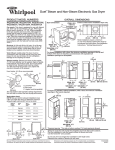
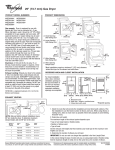
PRODUCT DIMENSIONS
MGDE900V
Electrical: 120 Volt, 60 Hz., AC only, 15- or 20-amp
fused electrical supply is required. A time-delay fuse or
circuit breaker is recommended. It is also recommended
that a separate circuit serving only this dryer be provided.
Exhaust venting: Exhaust your dryer to the outside.
4" (10.16 cm) diameter vent is required. Rigid or flexible
heavy metal exhaust vent must be used. Do not use
plastic or metal foil vent. Exhaust outlet hood must be at
least 12" (30.5 cm) from the ground or any object that
may be in the path of the exhaust.
Gas supply: This dryer is equipped for use with
Natural gas. It is design-certified by CSA International for
LP (propane or butane) gases with appropriate
conversion.
No attempt shall be made to convert the appliance from
the gas specified on the model/serial rating plate for use
with a different gas without consulting your gas
company.
Must include 1/8" NPT minimum plugged tapping
accessible for test gauge connection, immediately
upstream of the gas connection to the dryer.
1/2" IPS pipe is recommended.
3/8" approved aluminum or copper tubing is acceptable
for lengths under 20 ft (6.1 m) if local codes and gas
supplier permit.
If you are using Natural gas, do not use copper tubing.
Lengths over 20 ft (6.1 m) should use larger tubing and
a different size adapter fitting.
If your dryer has been converted to use LP gas, 3/8" LP
compatible copper tubing can be used. If the total length
of the supply line is more than 20 ft (6.1 m), use larger
pipe.
NOTE: Pipe joint compounds that resist the action of LP
gas must be used. Do not use TEFLON® tape.*
Use an elbow and a 3/8" flare x 3/8" NPT adapter fitting
between the flexible gas connector and the dryer gas
pipe, as needed to avoid kinking.
This dryer must be connected to the gas supply line with
a listed flexible gas connector that complies with the
standard for connectors for gas appliances, ANSI Z21.24
or CSA 6.10.
An individual manual shutoff valve must be installed
within six (6) feet (1.8m) of the dryer in accordance with
the National Fuel Gas Code, ANSI Z223.1. The location
should be easy to reach for opening and closing.
*®TEFLON is a registered trademark of E.I. Dupont De
Nemours and Company
Dryer gas pipe: The gas pipe that comes out through
the rear of your dryer has a 3/8" male thread.
*6¼"
(15.9 cm)
* Most installations require a minimum 5”
(12.7 cm) clearance behind the dryer for the
exhaust vent with elbow. See Use and Care
Guide, “Venting Requirements.”
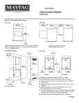
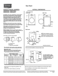
RECESSED AREA AND CLOSET INSTALLATION
For closet installation, with a door, the minimum ventilation openings in the top and bottom of the door
are required. Louvered doors with equivalent air ventilation openings in the top and bottom are
acceptable.
Dryer on pedestal
Dryer only
A. Side view – closet or confined area
B. Closet door with vents
* Required spacing
** Side or bottom venting – 0" (0 cm) spacing is allowed
A. Recessed area
B. Side view – closet or confined area
* Required spacing
** Side or bottom venting – 0" (0 cm) spacing is allowed
RECOMMENDED INSTALLATION SPACING FOR CABINET INSTALLATION
For cabinet installation, with a door, the
minimum ventilation openings in the top
of the cabinet are required.
B
1½"
(3.8 cm)
A
A. ½" NPT gas supply line
B. 3/8” NPT dryer pipe
NOTE: If the dryer is mounted on a pedestal, the gas pipe
height must be an additional 10" (25.4 cm) or 15.5"
(39.4 cm) from the floor, depending on the pedestal
model. For a garage installation, the gas pipe height must
be an additional 18" (46 cm) from the floor.
* Required spacing
** Side or bottom venting – 0" (0 cm) spacing is allowed
Page 1 of 2
Because Whirlpool Corporation policy includes a continuous commitment to improve
our products, we reserve the right to change materials and specifications without notice.
Dimensions are for planning purposes only. For complete details, see Installation
Instructions packed with product. Specifications subject to change without notice.
Ref. W10057354
07-29-08
Gas Dryer
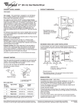
RECOMMENDED INSTALLATION SPACING FOR RECESSED OR CLOSET
INSTALLATION, WITH STACKED WASHER AND DRYER
PRODUCT MODEL NUMBERS
MGDE900V
Dimensions shown are for recommended spacing.
EXHAUST VENTING
48 in.2 *
(310 cm2)
6"* (15.2 cm)
Recommended hood styles
3"* (7.6 cm)
B
Angled hood style is
acceptable.
A
4"
(10.2 cm)
76"
(193 cm)
4"
(10.2 cm)
2-1/2"
(6.4 cm)
4"
(10.2 cm)
3"* (7.6 cm)
A. Louvered hood style
B. Box hood style
Number of
90° turns
or elbows
2
24 in. *
(155 cm2)
Type of
vent
Box or
Louvered
hoods
Angled
hoods
0
Rigid metal
Flexible metal
64 ft (20 m)
36 ft (11 m)
58 ft (17.7 m)
28 ft (8.5 m)
1
Rigid metal
Flexible metal
54 ft (16.5 m)
31 ft (9.4 m)
48 ft (14.6 m)
23 ft (7 m)
2
Rigid metal
Flexible metal
44 ft (13.4 m)
27 ft (8.2 m)
38 ft (11.6 m)
19 ft (5.8 m)
3
Rigid metal
Flexible metal
35 ft (10.7 m)
25 ft (7.6 m)
29 ft (8.8 m)
17 ft (5.2 m)
Rigid metal
Flexible metal
27 ft (8.2 m)
23 ft (7 m)
21 ft (6.4 m)
15 ft (4.6 m)
4
1"* (2.5 cm)
5"*
(12.7 cm)
1"
(2.5 cm)
27"
(68.6 cm)
1"
(2.5 cm)
* Required spacing
UNDERCOUNTER INSTALLATION
Dimensions shown are for minimum spacing.
0"
(0 cm)
38" min.
(96.52 cm)
1"*
(2.5 cm)
NOTE: Side and bottom exhaust installations have a 90° turn
inside the dryer. To determine maximum exhaust length, add one
90° turn to the chart.
27"
(68.6 cm)
1"*
(2.5 cm)
* Required spacing
Select the route that will provide the straightest and most
direct path outdoors. Plan the installation to use the fewest
number of elbows and turns. Use the fewest 90° turns
possible.
Do not use vent runs longer than specified in vent length
chart.
Determine the number of elbows you will need.
Page 2 of 2
Because Whirlpool Corporation policy includes a continuous commitment to improve
our products, we reserve the right to change materials and specifications without notice.
Dimensions are for planning purposes only. For complete details, see Installation
Instructions packed with product. Specifications subject to change without notice.
Ref. W10057354
07-29-08