Transcript
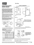
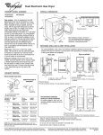
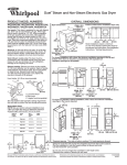
29" and 27" Wide Model Gas Dryer
PRODUCT MODEL NUMBERS
MGDC200X, MGDC300X, MGDX500X,
MGDX550X, MGDX600X, MGDX700X
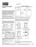
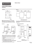
OVERALL DIMENSIONS
29" Wide Model Dryer dimensions
For closet installation, with a door,
the minimum ventilation openings in
the top and bottom of the door are
required. Louvered doors with
equivalent air ventilation openings
are acceptable.
Gas supply: This dryer is equipped for use with Natural gas. Dryer
can be converted to L.P. gas. When rigid pipe is used it should be
1/2" IPS. When acceptable to the gas supplier and local codes, 3/8"
approved tubing may be used for lengths under 20 ft (6.1 m).
For lengths over 20 ft (6.1 m), larger tubing should be used. Pipejoint compounds resistant to the action of L.P. gas must be used.
An individual manual shutoff valve must be installed within 6 ft (1.8
m) of the dryer in accordance with the National Fuel Gas Code ANSI
Z223.1.
A. Large opening side-swing door
B. Large opening side-swing door
C. Wide opening side-swing door
D. Wide opening hamper door
Electrical: A 120-volt, 60 Hz, AC-only, 15 or 20 amp fused electrical
supply is required. A time-delay fuse or circuit breaker and a
separate circuit are recommended.
Water (Steam models only): The dryer must be connected to the
cold water faucet using new inlet hoses. Do not use old hoses. Do
not overtighten. Damage to the coupling can result.
Exhaust venting: Exhaust your dryer to the outside. 4" (102 mm)
diameter vent is required. Rigid or flexible metal exhaust vent must
be used. Do not use plastic or metal foil vet. Exhaust hood must be
at least 12" (305 mm) from the ground or any object that may be in
the path of the exhaust.
Hood styles: A & B are recommended.
Installation Spacing
C
4"
(102 mm)
B
14" max.*
(356 mm)
18"*
(457 mm)
A
A. Recessed area
B. Side view - closet or confined area
C. Closet door with vents
2½"
(64 mm)
4"
(102 mm)
24 in.2 * 2
(155 cm )
A. Louvered hood
B. Box hood
C. Angled hood (acceptable)
4"
(102 mm)
1"
(25 mm)
The vent system chart provides venting requirments that will help to
achieve the best drying performance.
Vent system chart:
NOTE: Side and bottom exhaust installations for 27" have a 90° turn
inside the dryer. To determine maximum exhaust length, add one 90°
turn to the chart.
Vent System Chart
Number of
90° turns or
elbows
Type
of vent
Box/louvered
hoods
Angled
hoods
0
Rigid metal
64 ft. (20 m)
58 ft. (17.7 m)
1
Rigid metal
54 ft. (16.5 m)
48 ft. (14.6 m)
2
Rigid metal
44 ft. (13.4 m)
38 ft. (11.6 m)
3
Rigid metal
35 ft. (10.7 m)
29 ft. (8.8 m)
4
Rigid metal
27 ft. (8.2 m)
21 ft. (6.4 m)
29"
(737 mm)
A
Number of
90° turns
or elbows
Type
of vent
0
Rigid metal
23¾"
(603 mm)
43 "
(1092 mm)
43 "
(1092 mm)
*29 1/2"
(749 mm)
27"
(687 mm)
100 ft. (30.5 m)
Rigid metal
90 ft. (27.4 m)
4
Rigid metal
80 ft. (24.4 m)
5
Rigid metal
70 ft. (21.3 m)
27"
(687 mm)
B
14" max.*
(356 mm)
18"*
(457 mm)
(310 cm )
2
2
1"
(25 mm)
27"
(686 mm)
A
A. Large opening side-swing door
B. Wide opening hamper door
3"*
(76 mm)
2
48 in.*
24 in.* 2
(155 cm )
110 ft. (33.5 m)
Rigid metal
*29 1/2"
(749 mm)
Installation Spacing
120 ft. (36.6 m)
3
13¾"
(349 mm)
A
Box/louvered, or
Angled hoods
2
*Required spacing
C
27" Wide Model Dryer dimensions
Installation Spacing
Rigid metal
3"*
(76 mm)
27¾"
1"*
1"
(25 mm) (25 mm) (705 mm)
B
Vent System Chart
(29" Wide Long Vent Models Only)
1
3"*
(76 mm)
48 in.2*
2
(310 cm )
1"* 29¼" 5½"*
1"
(25 mm) (25 mm) (743 mm) (140 mm)
B
*Required spacing
3"*
(76 mm)
C
A. Recessed area
B. Side view - closet or confined area
C. Closet door with vents
Select the route that will provide the straightest and most direct path outdoors. Plan the installation to use
the fewest number of elbows and turns. Use the fewest 90° turns possible.
Do not use vent runs longer than specified in vent length chart.
Determine the number of elbows you will need.
Because Whirlpool Corporation policy includes a continuous commitment to improve
our products, we reserve the right to change materials and specifications without notice.
Dimensions are for planning purposes only. For complete details, see Installation
Instructions packed with product. Specifications subject to change without notice.
Ref. W10096984A
05/2010