1
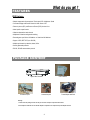
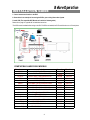
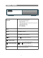
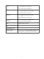
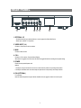
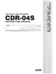
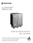
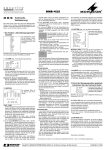
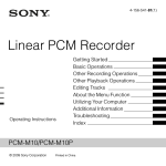
4 CH Digital Video Recorder
User’s Manual
Please read this instructions thoroughly before operation and keep the manual in a safe
place for further reference.
771-A V 1.0
WARNING
All the safety and operating instructions should be read before operation. The improper operation may cause
permanent damage.
• This adaptor is only for this machine. Do not use it for other electronic products or it may damage other products.
• Please lift and place this equipment gently.
• Do not expose this equipment from direct sunlight and keep it away from sources of intense heat.
• Do not use this equipment near water or in contact with water.
• Avoid dusty or humid place.
• Do not switch the Power On & Off within short period of time (within 3 seconds).
• Do not block the ventilation holes at the top and bottom of the unit.
• Do not attempt to service this equipment by yourself.
• Installation should be made by qualified service personnel.
• Do not try to retrieve the HDD data by PC.
The lightning flash with arrowhead symbol, within an equilateral triangle, is intended to alert
the user to the presence of uninsulated "dangerous voltage" within the product's enclosure that
may be of sufficient magnitude to constitute a risk of electric shock to persons.
The exclamation point within an equilateral triangle is intended to alert the user to the presence
of important operating and maintenance-(servicing) instructions in the literature accompanying
the appliance.
1
TABLE OF CONTENTS
What do you get ?
• FEATURES ---------------------------------------------------------------------------------------- 3
• PACKAGE CONTENT --------------------------------------------------------------------------
3
Before Operation
• INSTALLATION GUIDE ------------------------------------------------------------------------
4
• FRONT PANEL -----------------------------------------------------------------------------------
5
• REAR PANEL -------------------------------------------------------------------------------------
7
Basic Operation
• GETTING STARTED------------------------------------------------------------------------------ 8
• OPERATION ---------------------------------------------------------------------------------------- 8
Detailed Menu Setup
• MAIN MENU ---------------------------------------------------------------------------------------
10
• MENU OPTIONS ---------------------------------------------------------------------------------
10
Advanced Operation
• OPERATION OPTIONS ------------------------------------------------------------------------ 16
• KEY LOCK ---------------------------------------------------------------------------------------- 17
• RS-232 PROTOCOL ---------------------------------------------------------------------------- 17
• TROUBLE SHOOTING--------------------------------------------------------------------------- 17
• SPECIFICATIONS--------------------------------------------------------------------------------- 18
APPENDIX #1 – INSTALL THE HDD ---------------------------------------------------------- 19
APPENDIX #2 – REPLACE THE HDD -------------------------------------------------------- 19
APPENDIX #3 – PIN CONFIGURATIONS --------------------------------------------------- 20
APPENDIX #4 – RECORDING SPEED---------------------------------------------------------- 22
APPENDIX #5 – NETWORK APPLICATION-------------------------------------------------- 23
2
What do you get ?
FEATURES
DVR Features
• Wavelet compression format replaces Time-Lapse VCR + Multiplexer / Quad
• On Screen Display and Remote Control via Video Server & PC
• Picture-in-picture (PIP) and Picture-on-Picture (POP) function in live
• Alarm input & output function
• Video loss detected on each channel
• Multiplexer & Quad recording mode switching
• Recording rate up to full size 30 fields/sec. or Quad size 240 fields/sec.
• Support 1 HDD, IDE TYPE (over 250 GB)
• Multiple quick search by date/time, alarm, full list
• Security password protection
• RS-232, RS-485 communication protocol
PACKAGE CONTENT
User’s Manual
Digital Video Recorder
Accessories pack
Accessories pack
Power Adapter and Cord
Warning:
1. Please check the package to make sure that you receive the complete components shown above.
2. This adaptor is DC19V 2A. User can find the adaptor for replacement at a computer shop if the adaptor is broken.
3
INSTALLATION GUIDE
Before Operation
1. Connect cameras and monitor to the DVR.
2. Shown below is an example of connecting the DVR to your existing Observation System.
3. Install HDD (The compatible HDD Brands are listed in the following table.)
Please refer to page 19. Appendix #1 for installation instructions.
*The HDD must be installed before turning on the DVR. If HDD is not installed, the DVR would function as a 4 CH multiplexer.
COMPATIBLE HARD DISK MODELS
Manufacturer
Capacity
Rotation
HITACHI
HITACHI
HITACHI
Deskstar 180 GXP (120 GB)
Deskstar 7K250, HDS722516VLAT20
Deskstar 7K250, HDS722525VLAT80
Model
120GB
160GB
250GB
7200 rpm
7200 rpm
7200 rpm
IBM
IBM
Maxtor
Deskstar 120GXP (80GB)
Deskstar 120GXP (120GB)
DiamondMax 536DX(60GB) 4W060H4
80GB
120GB
60GB
7200 rpm
7200 rpm
5400 rpm
Maxtor
Maxtor
Maxtor
Maxtor
Seagate
Seagate
DiamondMax Plus 9
DiamondMax Plus 9, Model#6Y120L
DiamondMax Plus 9, Model#6Y160L0
80GB
120GB
160GB
250GB
80GB
120GB
7200 rpm
7200 rpm
7200 rpm
7200 rpm
7200 rpm
7200 rpm
Seagate
Barracuda 7200.7 Plus, ST3160023A
Western Digital Caviar WD1200BB-00CAA1
160GB
120GB
7200 rpm
7200 rpm
Western Digital Caviar WD2000BB-00DWA0
Western Digital CaviarSE WD2500JB
200GB
250GB
7200 rpm
7200 rpm
MaxLine Plus Ⅱ, Model#7Y250P0
Barracuda ATA IV, ST380021A
Barracuda ATA V, ST3120023A
4
FRONT PANEL
LED LIGHT
The LED Light is ON under following condition.
•HDD : HDD is reading or recording.
•HDD Full : HDD is full
•ALARM : To turn off the ALARM LED light, please refer to page.13 and
set the ALARM mode as OFF.
•TIMER : When Timer is Enabled
•PLAY : Playing mode
•REC : Recording mode
MENU
Press MENU to enter main menu.
ENTER
Press ENTER for confirmation
SEARCH
Press SEARCH for searching recorded video.
/ POP
Press “
” button for Picture on Picture screen.
/+ Picture in Picture
PIP: Press “PIP” button for Picture in Picture screen.
+ : Press “+ ” button can change the setting in the menu.
/- 4-channel display mode
: Press “
” button for 4 CH display modes
- : Press “ - ” button can change the setting in the menu.
SLOW
To slow down the speed of playing mode.
5
FF / ►
•FF : Play video fast forward. (Press FF button again to
adjust speed from 1, 2, 4, 8, 16, 32 times)
• ► : Under setup mode, it works as Right button.
REW / ◄
•REW : Play video fast backward. (Press REW button
again to adjust speed as 1, 2, 4, 8, 16, 32 times)
• ◄ : Under setup mode, it works as Left button.
STOP / ▼
•STOP : Under DVR Record / Play mode, it can stop the
action.
• ▼ : Under setup mode, it works as Down button.
•Pause : Under DVR play mode, it can pause the action.
PAUSE / ▲
PLAY
REC
• ▲ : Under setup mode, it works as Up button.
Press PLAY to playback recorded video.
Press REC to start recording.
CAMERA SELECT (1-4)
Press the Camera Select (1-4) to select the channel.
ENTER + SEARCH
During the LIVE or PLAY mode, press both “ENTER” and “SEARCH” buttons
to switch the “NORMAL” or“SHARPNESS” display. (refer to page.9)
6
REAR PANEL
IN
1
2
OUT
3
4
MAIN
CALL
DC 19V
EXTERNAL I/O
1
2
4
5
6
1. EXTERNAL I/O
•Controlled remotely by an external device or control system like Video Web Server.
•Alarm input, external I / O expansion.
2. VIDEO INPUT (1-4)
Connect to video source, such as camera.
3. MAIN
Connect to Main monitor.
4. CALL
Connect to CALL monitor. Show the Switch Display.
When alarm is triggered, the call monitor will show the triggered channel according to the system setting.
5. POWER
Please use the provided power cord.
Warning:
1. This adaptor is only for this machine. Do not use it for other electronic product or it may damage other products.
2. This adaptor is DC19V 2A. User can find the adaptor for replacement at a computer shop if the adaptor is broken.
6. FAN (OPTIONAL)
For ventilation.
Note: If the ambient temperature is high or ambient ventilation is bad, we suggest to install a fan on the rear panel.
7
Basic Operation
GETTING STARTED
Before using the DVR, please have a HDD installed ready, or it will function as 4 CH multiplexer (refer to Appendix #1 for
installation or removal of a HDD).
1. Connect the AC power cord and plug into an electrical outlet. The POWER LED will turn into orange color, and other
red LED indicators will turn ON. It takes approximately 5 to 15 seconds to boot the system with the message : “ HDD
Detecting ”. Once successfully connected, the POWER LED will change to green color, and the Alarm LED will be ON.
2. Before operating the DVR, set the system time first. (refer to page.10).
NOTE : 1. If the HDD is not installed correctly or not installed, the “HDD not found” message will
appear for 3 seconds and then return to 4 CH Multiplexer display mode.
2. To switch the system, pull out the AC power cord, before you reconnect the power,
press “FF” to NTSC system or “REW” to PAL system and then reconnect the AC power
cord, the DVR will auto-detect the system.
OPERATION
RECORDING
The DVR offers 3 recording modes. Refer P.22 for advanced setting of recording speed and
resolution. Under the recording status, if power is off accidentally, recorded video will still be stored in the HDD. DVR will
return to original recording setting after power restores again.
While you press “REC” button, on the screen, you will find the date, time, recording type, the
available HDD space in GB and the letter “
” represents the recording mode.
(OW : HDD Overwrite)
NOTE : 1. When the HDD is full under O/W Recording mode, previous recorded files will be overwritten
without further warning notices.
2. If the HDD space is only 5 GB left, it will display “5 GB” on the up-right screen in
orange color, and it will buzz for seconds; so as in 4GB, 3GB, 2GB and 1GB. If the O/W
Recording mode (NOTE 1) is on, it won’t have the warning buzzer.
(OW : HDD Overwrite)
There are 3 recording modes: Alarm, Timer and Manual Recording.
1. ALARM RECORDING
DVR is triggered by an alarm input.
2002 – JAN –01 01:02:03
●OW
symbol will be shown on the triggered channel. (refer to page13)
2. TIMER RECORDING
Recording is scheduled by a Timer. It will indicate by the symbol
. (refer to page11)
3. MANUAL RECORDING
Recording is initiated manually by pressing the REC button. Symbol
8
will be shown.
PLAY BACK
Press “ PLAY ” button, the DVR will show the last recording.
1. FAST FORWARD (F.F.) & FAST REWIND (F.R.)
You can increase the speed of Fast Forward and Rewind on the DVR.
In the Play mode, press “ ► ” once to get 2X speed forward and press twice to get 4X speed,… and the maximum
speed can reach 32X.
Press “◄ ” once to get 1X speed rewind and press twice to get 2X speed, … and the maximum speed can reach
32X.
2. SLOW FORWARD (S.F.) & SLOW REWIND (S.R.)
You can also slow down the speed of Forward and Rewind on the DVR.
In the Play mode, press the SLOW button and you will enter Slow mode.
Press “ SLOW ” once to get 1/2X speed forward and press “ ► ” to get 1/4X speed,… and the slowest speed can
reach 1/32X.
Press “◄ ” once to get 1/2X speed rewind and press twice to get 1/4X speed, … and the slowest speed can reach
1/32X.
3. PAUSE
You can pause the playback and the image will be displayed on the screen.
4. STOP
Press “ STOP ” button under any circumstance, DVR will return to live monitoring mode.
5. IMAGE JOG DIAL
It will allow you to manually view video frame-by-frame, one image at a time.
While in PLAY mode, press “ PAUSE ”, it will pause the screen.
Press “ ► ” button advances the frozen screen one image forward.
Press “ ◄ ” button moves back one image.
Note: During the LIVE or PLAY mode, press both “ENTER” and “SEARCH” buttons to switch the “NORMAL” or
“SHARPNESS” display.
CAMERA SELECT (1-4)
Press Camera Select (1-4) to select the camera to display in full screen.
9
Detailed Menu Setup
MAIN MENU
There are 11 options available in the Main Menu:
(MENU)
TIMER
CAMERA
RECORD
ALARM
DWELL
PIP
DISPLAY
REMOTE
USER
SYSTEM
EVENT
TIMER ---------- Program Timer Recording
CAMERA ------- Camera Setup
RECORD ------- Recording Mode Setup
ALARM --------- Alarm Setup
DWELL --------- Dwell time Setup
PIP --------------- Picture in Picture Setup
DISPLAY ------- Display Mode Setup
REMOTE ------- Remote Control Setup
USER ----------- User Password Setup
SYSTEM ------- System Setup
EVENT --------- Event List
Outlined below are the buttons used for Menu setting :
•“▲” and “▼” : Scroll up and down within a menu option
•“◄” and “►” : Scroll sideways within a menu option that has been selected
•“ + ” and “ - ” : Increase and decrease the number or change values when an option is selected and is blinking
•ENTER : Select a submenu / an option under a submenu for browsing / modification
•MENU : Complete modification of a menu option; exit a menu
MENU OPTIONS
SYSTEM
1. BUZZER
Set the BUZZ “ON”, it will buzz by event occurrence.
2. EXT ALARM
To set the EXT ALARM. It will be trigged by event occurrence when the setting is ON.
3. VLOSS ALARM
To set the VLOSS ALARM. When the setting is “ON”, the alarm will start by the setting
of Buzzer, EXT alarm or Alarm Duration.
4. KEY MUTE
To set the KEY MUTE. When the setting is “YES”, there will be no sound when you press any key.
5. HDD OVERWRITE
To set the HDD OVERWRITE. When the HDD is full under O/W recording mode, previously recorded
files will be overwritten without further warning notices when the HDD OVERWRITE is ON.
10
(MENU)
TIMER
CAMERA
RECORD
ALARM
DWELL
PIP
DISPLAY
REMOTE
USER
SYSTEM
EVENT
6. MESSAGE LATCH
To select whether the DVR messages will disappear after 10
seconds or remain on screen. NO is the default setting which the
messages will disappear after 10 sec.
NOTE : Video loss, and Alarm messages will be shown
the same as Alarm Duration time.
7. DATE DISPLAY
To set the date Y/M/D, M/D/Y, D/M/Y and OFF on monitor or not.
8. DATE
To set the date on the DVR.
9. TIME
(SYSTEM)
BUZZER
ON
EXT ALARM
ON
VLOSS ALARM
ON
KEY MUTE
YES
HDD OVERWRITE
YES
MESSAGE LATCH
YES
DATE DISPLAY
D/M/Y
DATE
26-DEC-2003 [FRI]
TIME
22:55:34
CLEAR HDD
YES
SYSTEM RESET
YES
To set the time on the DVR.
10. CLEAR HDD
Delete all the contents of the HDD. When you choose “YES” on this option, press “ENTER” and you
will be prompted with the question shown: Press “→” to clear HDD or press ”←” to cancel.
11. SYSTEM RESET
Reset all system to the factory default settings. Select “YES” and press “ENTER” button.
TIMER
1. DAY
Select the day, or days of the week (Mon–Fri / Sat-Sun / Daily) that you wish to schedule
the DVR to automatically record.
NOTE :
1. Change the date by “+” and “-” buttons.
2. If you have selected the date and Timer recording set from that specific day
to a new day, then the Timer Recording Schedule will be set as whole week.
For specific date of Timer Recording Schedule, it is not recommended to set
Ending Time over 23:59. For example: If you set Timer Schedule Day as Sunday,
and START from 11:30, but End on 00:20, then Recording Timer Schedule is
set as from every Sunday's 11:30 to next Sunday‘s 00:20. If you only want to set
Recording Timer Schedule from every Sunday 11:30 to Monday 00:20, then you
should set Recording Timer Schedule as Sunday from 11:30 to 23:59, and Monday
from 00:00 to 00:20.
3. It is not suggested that users press “STOP” button or restart the system during setting
time. In doing so, the recording will stop, and users can resume recording by pressing
“ENTER” + “MENU”.
11
(MENU)
TIMER
CAMERA
RECORD
ALARM
DWELL
PIP
DISPLAY
REMOTE
USER
SYSTEM
EVENT
(TIMER)
DAY START END IPS
DAILY 01:00 22:00 30
OFF 00:00 00:00 30
OFF 00:00 00:00 30
OFF 00:00 00:00 30
OFF 00:00 00:00 30
OFF 00:00 00:00 30
OFF 00:00 00:00 30
OFF 00:00 00:00 30
TIMER ENABLE : YES
2. START
Set the time to start the recording.
3. END
Set the time to end the recording.
4. IPS (IMAGES PER SECOND)
NTSC-30、15、8、4、2、1
PAL-25、12、6、3、2、1
QLT MODE
BEST Q-FR
BEST Q-FI
BEST Q-FI
BEST Q-FR
BEST Q-FR
BEST Q-FR
BEST MUX
BEST Q-FI
5. QUALITY
Select the quality of recording image: BEST, HIGH, NORM and BASE.
6. MODE
There are three recording mode settings :
QUAD-FRAME, QUAD-FIELD, MULTIPLEX.
NOTE: To ensure the best recording quality, we don’t suggest
the users switch a different recording mode during
the period of recording.
7. TIMER ENABLE
When TIMER ENABLE is “YES”, press “menu” button, you
can see the timer diagram according to your setting.
CAMERA
1. TITLE
Assign a title to each camera. Initially each title is the camera’s number.
(Max: 8 characters)
2. ALARM
Select LOW / OFF / HIGH for alarm polarity. The default value is LOW.
(CAMERA)
ALARM
REC
BR
CT
CL
HUE
CAMERA01
LOW
ON
18
15
15
18
CAMERA02
OFF
OFF
18
15
15
18
CAMERA03
HIGH
OFF
18
15
15
18
CAMERA04
HIGH
ON
18
15
15
18
TITLE
12
(MENU)
TIMER
CAMERA
RECORD
ALARM
DWELL
PIP
DISPLAY
REMOTE
USER
SYSTEM
EVENT
3. REC (RECORD)
Set up which channel you want to record.
ON : when alarm input is triggered, DVR will record alarming channel more frequently.
For example : when CH01 is triggered, the record method will become 1-2-1-3-1-4….
OFF : DVR will not record.
4. BR (BRIGHTNESS)
Adjust the brightness of each channel. The level is from 0 to 63.
5. CT (CONTRAST)
Adjust the contrast of each channel. The level is from 0 to 63.
6. CL (COLOR)
Adjust the color of each channel. The level is from 0 to 63.
7. HUE (HUE)
Adjust the hue of each channel. The level is from 0 to 63.
(MENU)
TIMER
CAMERA
RECORD
ALARM
DWELL
PIP
DISPLAY
REMOTE
USER
SYSTEM
EVENT
RECORD
1. RECORD IPS
Select the recording speed. The options are
as following :
NTSC-30、15、8、4、2、1
PAL-25、12、6、3、2、1
2. QUALITY
There are four quality settings : BEST, HIGH, NORMAL, BASIC.
NOTE : The relationship of Record time, IPS and Record quality,
please refer to page.22 Recording Speed.
3. RECORD MODE
There are three recording settings : QUAD-FRAME, QUAD-FIELD,
MULTIPLEX.
(RECORD)
RECORD IPS
QUALITY
RECORD MODE
30
NORMAL
QUAD-FRAME
ALARM
1. ALARM ENABLE
Alarm will be triggered by event occurrence when the setting is
YES.
2. ALARM DURATION
Set the reaction time of the alarm mode responds to a buzzer.
Default setting is 10 Sec. Options are 10 Sec, 15 Sec, 20 Sec,
30 Sec, 1 MIN, 2 MIN, 3 MIN, 5 MIN, 10 MIN, 15 MIN, 30 MIN,
ALWAYS, AUTO.
NOTE : 1. Video loss, and Alarm messages will be shown the same as Alarm Duration time.
2. When the setting is AUTO, the alarm duration time is according to the setting of the
external alarm device.
3. During ALARM DURATION’S setting time, users can restart ALARM function by
pressing both “ENTER” + “STOP” buttons.
13
(MENU)
TIMER
CAMERA
RECORD
ALARM
DWELL
PIP
DISPLAY
REMOTE
USER
SYSTEM
EVENT
3. REC IPS
Select the images per second of recording during an ALARM. The options are as following:
NTSC-30、15、8、4、2、1
PAL-25、12、6、3、2、1
(ALARM)
ALARM ENABLE
YES
4. QUALITY
ALARM DURATION
15 MIN
There are four recording quality settings during an ALARM :
RECORD IPS
30
BASIC, BEST, HIGH, NORMAL.
QUALITY
NORMAL
5. RECORD MODE
RECORD MODE
QUAD-FRAME
There are three recording settings : QUAD-FRAME, QUAD-FIELD,
MULTIPLEX.
DWELL
1. NORM
To set up the DWELL time period that each channel auto sequentially shows on call
monitor. The level is from 1 to 15 Sec or OFF.
2. ALARM
To set up the DWELL time period when alarm input is triggered. The level is from 1 to
15 Sec or OFF.
PIP
(DWELL)
NORM ALARM
CAM1
01
01
CAM2
01
01
CAM3
01
01
CAM4
01
01
1. FULL SCREEN
To set up the full screen background picture display.
2. PIP SCREEN
To set up the picture with a 1/9 size screen “insert”.
3. POSITION
There are six position settings : D/L, D/M, D/R, U/L, U/M, U/R.
DISPLAY
(PIP)
FULL SCREEN
PIP SCREEN
POSITION
1. TITLE DISPLAY
To set the title shown on monitor or not.
2. OSD COLOR
Select the OSD (On Screen Display) color. The options are
YELLOW, GREEN, CYAN, BLUE, PINK, GRAY, WHITE, RED.
14
CAM 1
CAM 2
D/R
(MENU)
TIMER
CAMERA
RECORD
ALARM
DWELL
PIP
DISPLAY
REMOTE
USER
SYSTEM
EVENT
(MENU)
TIMER
CAMERA
RECORD
ALARM
DWELL
PIP
DISPLAY
REMOTE
USER
SYSTEM
EVENT
3. LOSS SCREEN
Retain the last picture or select the LOSS SCREEN color.
The options are GREEN, BLACK, BLUE and RETAIN.
4. TIME POSITION
To set the OSD POSITION shown on monitor.
The options are NORMAL or CENTER.
(DISPLAY)
TITLE DISPLAY
OSD COLOR
LOSS SCREEN
TIME POSITION
YES
YELLOW
GREEN
NORMAL
REMOTE
1. REMOTE MODE
Set the remote mode for connection with computer via RS-232 or RS-485.
(Please refer to page. 20& 21 for RS-232& RS-485 Remote Control).
2. BAUD RATE
Set the remote protocol transmitting baud rate. Available options are 115200,
57600, 19200, 9600, 4800, 3600, 2400, 1200.
3. ID
To control different DVR by setting
remote protocol. ID number can be set
from 000 to 255.
(REMOTE)
REMOTE MODE
BAUD RATE
ID
(MENU)
TIMER
CAMERA
RECORD
ALARM
DWELL
PIP
DISPLAY
REMOTE
USER
SYSTEM
EVENT
(MENU)
TIMER
CAMERA
RECORD
ALARM
DWELL
PIP
DISPLAY
REMOTE
USER
SYSTEM
EVENT
RS-485
9600
255
USER
1. USER
To set up the user account for controlling. It
allows 8 users setting.
Supervisor – Control all the functions.
Other Users – View all functions except the
menu setting.
2. PASSWORD
To set the security password for each account.
The maximum length of user’s password is 4
characters.
NOTE: To switch to different USER, press
“ENTER” + “MENU” buttons to “KEY
LOCK” and then enter the different user’s
password to UNLOCK.
(MENU)
TIMER
CAMERA
RECORD
ALARM
DWELL
PIP
DISPLAY
REMOTE
USER
SYSTEM
EVENT
15
(USER)
PASSWORD
SUPERVISOR
USER 1
USER 2
USER 3
USER 4
USER 5
USER 6
USER 7
0000
0000
0000
0000
0000
0000
0000
0000
EVENT
A single page can display 16 recorded events. Press “◄ ” or “► ” to change the
pages or press “▲ ” + “▼ ” to CLEAR the EVENT record.
DISK FULL: HDD is full
PWR REST : Power restored
M-HD REMS: HDD removal
M-HD REPL: HDD replace
(MENU)
TIMER
CAMERA
RECORD
ALARM
DWELL
PIP
DISPLAY
REMOTE
USER
SYSTEM
EVENT
M-HD ERR : HDD error
M-HD WARM: HDD warning
K UNLOCKS: Key is unlock
DMA ERROR: DMA error(Direct Memory Access)
C1 VLOSS : Video loss on Ch1
C2 ALARM : Channel 2 has been triggered by external I/O alarm
SYSTEM ERROR: System fail
POWER RESTORE : Power restored
OPERATION OPTIONS
C1 VLOSS
26-DEC-2002 03:00:00
C2 ALARM
26-DEC-2002 03:00:00
K UNLOCKS 26-DEC-2002 03:00:00
M-HD ERR
26-DEC-2002 03:00:00
M-HD WARM 26-DEC-2002 03:00:00
PWR REST
26-DEC-2002 03:00:00
DMA ERROR 26-DEC-2002 03:00:00
M-HD REPL 26-DEC-2002 03:00:00
↑+↓: CLEAR
Advanced Operation
VIDEO LOSS
Screen will display “VLOSS” in the center of display picture, if the video input is not connected properly.
SEARCH
1. LAST RECORD
Play the last recorded piece of video.
LAST RECORD
FULL LIST
ALARM LIST
TIME SEARCH
2. FULL LIST
List all recorded video on the HDD which sorted by time.
: Manual Recording
: Alarm Recording
: Timer Recording
M : Storage in Master HDD
S : Storage in Slave HDD
2003-JAN-01 01:02:03 M
2003-JAN-05 05:02:03 M
2003-MAR-12 04:02:03 M
2003-APR-02 03:02:04 M
2003-MAY-01 05:02:03 M
2003-AUG-09 01:02:01 M
← : PAGE UP → : PAGE DOWN
NOTE: It will display different color on each record list
mention above.
3. ALARM LIST
List all recorded video triggered by Alarm.
NOTE : If there are no Alarm in the record, the screen will
display “EMPTY”.
4. TIME SEARCH
Enter the specific time/date.
16
KEY LOCK
For advanced security, you can “Lock” the buttons on your DVR. Key-Lock prevents other people from using the system.
Press ENTER and MENU at the same time to enable Key Lock.
Press ENTER and MENU at the same time and key in password (Default : 0000), then press “ENTER“ to disable Key Lock.
NOTE: To switch to different USER, press “ENTER” + “MENU” buttons to “KEY LOCK” and then enter the different user’s
password to UNLOCK.
RS-232 REMOTE PROTOCOL
You can use the PC keyboard to simulate DVR keypad.
DATA: REMOTE PROTOCOL using 8 bit data、1 start bit、1stop bit
FUNCT ION CODE AS CII FUNCT ION CODE AS CII
KEY_MENU
KEY_SEARCH
KEY_ENTER
KEY_QUAD
KEY_POP
KEY_PIP
KEY_SLOW
KEY_REC
KEY_LEFT
KEY_UP
0x4D
0x73
0x0D
0x51
0x5A
0x70
0x53
0x72
0x4C
0x55
M
KEY_PLAY
s
KEY_DOWN
ENTER
KEY_RIGHT
Q
KEY_KEY_LOCK
Z
KEY_CH1
p
KEY_CH2
S
KEY_CH3
r
KEY_CH4
TIMER REC PROCEED
L
U
0x50
0x4E
0x52
0x4B
0x31
0x32
0x33
0x34
0X54
P
N
R
K
1
2
3
4
T
TROUBLESHOOTING
When malfunction occurs, it may not be serious and can be corrected easily. The following table describes the most
common problems with their solutions. Please read thoroughly before calling your DVR dealer.
PROBLEM
No power
SOLUTION
l Check power cord connections.
l Confirm that there is power at the outlet.
Not working when press any
button
No recorded video
Timer Record enable does not
working
No live video
l Check if it is under Key Lock mode.
l Press "MENU" & "ENTER" to exist Key Lock mode.
l Check if the HDD is installed properly.
l Check if the Time Enable is set to YES
l Check camera video cable and connections.
l Check monitor video cable and connections.
l Confirm that the camera has power.
l Check camera lens setting.
NTSC & PAL System switch
To switch the system, press “FF” to NTSC system and
“REW” to PAL system. (Refer to Page 8 "Getting Started").
17
SPECIFICATIONS
NTSC/EIA or PAL/CCIR
Video format
Hard disk storage
IDE type, UDMA 66, supported 250 GB HDD
Manual / Alarm / Timer
Record mode
Camera Input Signal
Composite video signal 1 Vp-p 75Ω BNC, 4 channels
Main Monitor Output
Composite video signal 1 Vp-p 75Ω BNC
Call Monitor Output
Composite video signal 1 Vp-p 75Ω BNC
Video Loss Detection
Refresh Rate
Recording Rate
Yes
Up to 240 fields/sec. for NTSC / 200 fields/sec. for PAL
Multiplex: Up to 30 fields/sec. for NTSC / 25 fields/sec. for PAL
Quad-field: Up to 120 fields/sec. for NTSC / 100 fields/sec. for PAL *
Quad-frame: Up to 240 fields/sec. for NTSC / 200 fields/sec. for PAL**
Dwell Time
Programmable (1~15 Sec)
Picture in Picture
Yes (Movable)
Key Lock
Yes
Camera Title
Video Adjustable
8 letters
Hue/ Color/ Contrast/ Brightness Adjustable
Alarm Input
TTL input, Hi (5V), Low (GND)
Alarm Output
COM./N.O/N.C
Remote Control
Time Display Format
RS-232 or RS-485
YY/MM/DD, DD/MM/YY, MM/DD/YY, OFF
Power Source
DC 19V
Power Consumption
<32W
Operation Temperature
10 ~ 40℃
RS-232C / RS-485 (bps)
115200、57600、19200、9600、4800、3600、2400、1200
Dimension (mm)
343(W) x 223(L) x 59(H)
Net Weight
1.5 kgs
• Specifications are subject to change without notice.
*NTSC: 4CH x 30IPS = 120 fields/sec, PAL: 4CH x 25IPS = 100 fields/sec
**NTSC: 4CH x 60IPS = 240 fields/sec,PAL: 4CH x 50IPS= 200 fields/sec
18
APPENDIX #1 – INSTALL THE HDD
Follow these steps carefully in order to ensure correct installation.
HDD Bracket
HDD Power Cable
Fig.1
HDD Power Cable
Fig.2
Fig.3
Step 1 Remove the lid and unscrew the screws from HDD bracket module .
Step 2 Insert the HDD into the HDD bracket and screw the four screws.
The bottom side is power side as chart shows (refer to the Fig 1).
Step 3 Connect the HDD power cable to the HDD (refer to the Fig. 2).
Step 4 Attach the HDD connector to the 40-pin pinhead, and screw the HDD and
the DVR machine together (refer to the Fig. 3).
Step 5 Pull the sides of the lid apart slightly and push the lid down.
Note: Do not try to retrieve the HDD data by PC. The video file cannot be read by PC,
operation on PC would damage the FAT table of the hard disk.
APPENDIX #2 – REPLACE THE HDD
Follow these steps carefully in order to ensure correct installation.
Step 1 Remove the lid.
Step 2 Unscrew the screws and take out the HDD from DVR machine carefully
(refer to the Fig 3).
Step 3 Remove the HDD power cable from the HDD (refer to the Fig. 2).
Step 4 Unscrew the four screws connected the hard drive to the bracket and remove the
HDD bracket module. Repeat those steps according to the “Install the HDD” section for
resetting another HDD (refer to the Fig 1).
Step 5 Pull the sides of the lid apart slightly and push the lid down.
Note: When HDD works for a period of time, the surface temperature will be high, please notice it.
19
APPENDIX #3 – PIN CONFIGURATIONS
15 pin com port
•
•
DVR
•
•
9 pin com port
•
•
DVR
DQR
•
•
20
PIN 1. RS232-TX : RS-232
DVR can be controlled remotely by an external device or control system, such as a control keyboard, using RS232 serial communications signals.
PIN 2. RS232-RX : RS-232
DVR can be controlled remotely by an external device or control system, such as a control keyboard, using RS232 serial communications signals.
PIN 3, 4, 5, 6 ALARM INPUT
To connect wire from ALARM INPUT (PIN 3, 4, 5, 6) to GND ( PIN 9 ) connector, DVR will start recording and
buzzer will be on. When alarm has been triggered, signal becomes “Low”, and it will stop all alarm activities.
Under normal operation, signal remains “High”.
PIN 7. EXTERNAL ALARM NC
Under normal operation COM connect with NC and disconnect with NO. But when alarm triggered, COM
disconnect with NC, and connect with NO.
PIN 8. EXTERNAL ALARM NO
Under normal operation, COM will disconnect from NO. But when Alarm triggered, COM will connect with NO.
PIN 9. GND
GROUND
PIN 10. RS485-B
DVR can be controlled remotely by an external device or control system, such as a control keyboard, using
RS485 serial communications signals.
PIN 11. RS485-A
DVR can be controlled remotely by an external device or control system, such as a control keyboard, using
RS485 serial communications signals.
PIN 12. DISK FULL (OUTPUT)
When HDD is full, it sends a signal to trigger next DVR record mode, if you install another DVR. Under normal
operation, the signal remains “High”. But when disk full, DVR will send the “Low” signal.
PIN 14. ALARM RESET (INPUT)
To connect wire from ALARM RESET ( PIN 14 ) to GND ( PIN 9 ) connector, it can disable ALARM. An external
signal to ALARM RESET ( PIN 14 ) can be used to reset both ALARM OUTPUT signal and DVR’s internal buzzer.
When alarm has been triggered, signal becomes “Low”, and it will stop all alarm activities. Under normal operation,
signal remains “High”.
PIN 15. EXTERNAL ALARM COM
Under normal operation COM connect with NC and disconnect with NO. But when alarm triggered, COM
disconnect with NC, and connect with NO.
21
APPENDIX #4 – RECORDING SPEED
The Record Time is different based on Recording Speed, Recording Quality and Recording Mode. Please
refer to following table. The HDD capability is 250GB.
NTSC SYSTEM
IPS
MULTIP
LEX
QUADFIELD
QUADFRAME
30
15
8
4
2
1
Best
50hr
100hr
187hr
375hr
750hr
1500hr
High
62hr
125hr
235hr
468hr
937hr
1875hr
Normal
100hr
200hr
375hr
750hr
1500hr
2998hr
Basic
167hr
333hr
625hr
1250hr
2498hr
4996hr
Best
48hr
95hr
178hr
356hr
712hr
1425hr
High
59hr
118hr
223hr
445hr
890hr
1781hr
Normal
95hr
190hr
356hr
712hr
1425hr
2848hr
Basic
158hr
316hr
594hr
1187hr
2373hr
4746hr
Best
24hr
48hr
89hr
178hr
356hr
713hr
High
30hr
59hr
112hr
223hr
445hr
890hr
Normal
48hr
95hr
178hr
356hr
713hr
1424hr
Basic
79hr
158hr
297hr
594hr
1187hr
2373hr
250 GB
HDD Type
PAL SYSTEM
IPS
MULTIP
LEX
QUADFIELD
QUADFRAME
25
12
6
3
2
1
Best
50hr
104hr
210hr
423hr
633hr
1266hr
High
62hr
131hr
265hr
527hr
792hr
1583hr
Normal
102hr
210hr
422hr
844hr
1266hr
2542hr
Basic
168hr
350hr
704hr
1406hr
2110hr
4218hr
Best
48hr
98hr
200hr
400hr
600hr
1202hr
High
58hr
124hr
251hr
500hr
752hr
1503hr
Normal
98hr
200hr
400hr
800hr
1202hr
2414hr
Basic
160hr
332hr
668hr
1335hr
2004hr
4005hr
Best
24hr
50hr
100hr
200hr
300hr
600hr
High
30hr
62hr
125hr
250hr
376hr
751hr
Normal
49hr
100hr
200hr
400hr
601hr
1207hr
Basic
80hr
166hr
334hr
667hr
1002hr
2003hr
250 GB
HDD Type
Note: Above data is obtained from actual test of recording normal TV program. (For Reference Only)
22
APPENDIX #5 – NETWORK APPLICATION
Video Web Server Features
• Compatible with most of CCTV Products; empower any video output device watching and
controlling on the Internet or LAN
• Auto Network Reconnection (ANR)
• Upgrade firmware & AP from FTP site via Video Web Server
• Watch dog function supported
• Support Dynamic IP address
• 4 alarm inputs supported
• Duplex function, record and playback simultaneously at client site
• Auto e-mail warning system which will remind you if external alarm
happened
• Intelligent non-stoppable recording function after ANR
Video Web Server
• Multi AP screens supported
• Unique video player
DVR Control
1 ) Connect the Sub-D plug of Video Web
Server with our own brand DVR products.
1/4 CH DVR
2 ) Set the “Remote” function in the DVR
products.
NOTE : Remote mode : RS-485,
Baud rate : 2400, ID : same
as “I/O port setting” in the Video
Web Server.
3 ) Set the “I/O Port Setting” in the system
config of Video Web Server.
Port1 : DMR-4, Device ID : 20.
23