Download Maxtor CDR-04S User's Manual

Transcript
WARNING
1
DVR
WARNING
All the safety and operating instructions should be read before operation. The improper operation of this device may
cause permanent damage.
‧ Please use the provided adapter (Other adapter is not suitable for this machine).
‧ Please lift and place this equipment gently.
‧ Do not expose this equipment to open sunlight.
‧ Do not use this equipment near water or in contact with water.
‧ Do not spill liquid of any kind on the equipment.
‧ Please power down the unit before unplugging.
‧ Do not switch the Power On & Off within short period of time (within 3 seconds).
‧ Do not attempt to service this equipment by yourself.
‧ Installation should be made by qualified service personnel.
The lightning flash with arrowhead symbol, within an equilateral triangle, is intended to alert
the user to the presence of uninsulated "dangerous voltage" within the product's enclosure that
may be of sufficient magnitude to constitute a risk of electric shock to persons.
The exclamation point within an equilateral triangle is intended to alert the user to the presence
of important operating and maintenance-(servicing) instructions in the literature accompanying
the appliance.
1
TABLE OF CONTENTS
DVR
What do you get ?
‧ FEATURES ----------------------------------------------------------------------------------------
3
‧ PACKAGE CONTENTS -------------------------------------------------------------------------
3
Before Operation
‧ INSTALLATION GUIDE ------------------------------------------------------------------------
4
‧ FRONT PANEL -----------------------------------------------------------------------------------
5
‧ BACK PANEL -------------------------------------------------------------------------------------
7
Basic Operation
‧ START THIS UNIT --------------------------------------------------------------------------------
8
‧ OPERATION ----------------------------------------------------------------------------------------
8
Detailed Menu Setup
‧ ACCESS MENU ----------------------------------------------------------------------------------
10
‧ MAIN MENU ---------------------------------------------------------------------------------------
10
‧ MENU OPTIONS ---------------------------------------------------------------------------------
11
‧ MOTION DETECTION --------------------------------------------------------------------------
14
Advanced Operation
‧ OPERATION OPTIONS ------------------------------------------------------------------------
16
‧ KEY LOCK ----------------------------------------------------------------------------------------
17
‧ RS-232 PROTOCOL ----------------------------------------------------------------------------
17
Trouble Shooting ---------------------------------------------------------------------------------- 17
Specifications -------------------------------------------------------------------------------------- 18
APPENDIX #1 – INSTALLING THE HDD ---------------------------------------------------- 19
APPENDIX #2 – PIN CONFIGURATIONS --------------------------------------------------- 21
APPENDIX #3 – RACK MOUNT ---------------------------------------------------------------- 23
APPENDIX #4 – RECORDING SPEED ------------------------------------------------------- 24
2
What do you get ?
FEATURES
DVR Features
• Wavelet Compression Format replaces Time-Lapse VCR + Multiplexer
• 4 Audio inputs / 2 Audio outputs (selectable 1-channel recording)
• On Screen Display and RTC (Real time clock) Function
• Support from 1 channel to 4 channels of video inputs
• Picture-In-Picture (PIP) is available in live and DVR playback modes
• Motion detection function and 4 Level video quality adjustable on each channel
• Alarm Input & Output Function
• Video loss detection on each channel (can record up to 160 events)
• Power-loss memory function
• Support 1 Removable HDD, IDE Type
• Quick Multiple Search by date/time, alarm, full list
• Security password protection
• RS-232, RS-485 communication protocol
PACKAGE CONTENTS
Digital Video Recorder(with HDD cartridge)
Bracket
User Manual
Alarm block
2 Keys for Cartridge
Power Adapter and Cord
NOTE : Please check the package to make sure that you receive all of the components shown above.
3
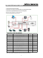
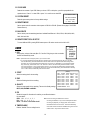
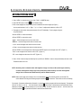
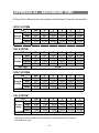
INSTALLATION GUIDE
Before Operation
1. Connect cameras and monitor with the DVR.
2. Shown below is one example for connecting the DVR to your existing Observation System.
3. Install HDD (The compatible HDD Brands are listed in the following table.)
Please refer to page.19 Appendix #1 for installation instructions.
The HDD must be installed before turning on the DVR.
COMPATIBLE HARD DISK BRANDS
HITACHI
Deskstar 180 GXP (120 GB)
120GB
7200 rpm
HITACHI
Deskstar 7K250, HDS722516VLAT20
7200rpm
HITACHI
Deskstar 7K250, HDS722525VLAT80
160GB
250GB
7200rpm
IBM
Deskstar 120GXP (80GB)
80GB
7200 rpm
IBM
Deskstar 120GXP (120GB)
120GB
7200 rpm
Maxtor
DiamondMax 536DX(60GB) 4W060H4
60GB
5400rpm
Maxtor
DiamondMax Plus 9
80GB
7200 rpm
Maxtor
DiamondMax Plus 9, Model#6Y120L
120GB
7200 rpm
Maxtor
DiamondMax Plus 9, Model#6Y160L0
160GB
7200rpm
Seagate
Barracuda ATA IV, ST380021A
80GB
7200rpm
Seagate
Barracuda ATA V, ST3120023A
120GB
7200 rpm
Seagate
Barracuda 7200.7 Plus, ST3160023A
160GB
7200 rpm
Western Digital
Caviar WD1200BB-00CAA1
120GB
7200rpm
Western Digital
Caviar WD2000BB-00DWA0
200GB
7200rpm
Note: This list changes constantly. Please contact local purchase point for the latest list.
4
DVR
FRONT PANEL
2
17
CDR-04S
HDD
1
1
2
3
MENU
ENTER
SEARCH
3 4 5
HDD FULL
TIMER
ALARM
4
SLOW
16
Z0 0M
6 7 8
REW
FF
14 12 13
1. REMOVABLE HDD CARTRIDGE
Please refer to page 19, Appendix #1.
2. LED LIGHT
The LED Light is ON under following conditions.
‧HDD Full : HDD is full
‧ALARM : If you want to turn off the ALARM LED light, please refer to page.13 and set the
Camera / ALARM item as OFF. (all of the cameras should be set as OFF.)
‧TIMER : When Timer is set as Enabled
‧PLAY : On Play mode
‧REC : On Recording mode
3. MENU
Press MENU to enter main menu.
4. ENTER
Press ENTER for confirmation.
5. SEARCH
Press SEARCH for searching recorded video.
6. ZOOM
Press ZOOM to enlarge the picture display.
7.
8.
Picture in Picture
Press PIP button for Picture in Picture screen.
4-Channel Display Mode
9. STOP / Down
.
‧STOP : Under DVR Record/Play mode, press 2~ 3 seconds then release it to stop recording.
‧DOWN : Under setup mode, it works as Down button.
10. PLAY
Press PLAY to playback recorded video.
5
STOP
9
PLAY
REC
POWER
10
15 11
11. POWER
Press Power to turn ON / OFF the DVR.
12. FF / Right
‧FF : It can play video forward at high speed, and press FF again to adjust speed from 1, 2, 4, 8, 16, 32 times.
‧Right : Under setup mode, it can work as Right button.
13. PAUSE / Up
‧Pause : Under DVR play mode, it can pause the action.
‧UP : Under setup mode, it works as Up button.
14. REW / Left
‧REW : Under DVR play mode, it can play video backward at different speeds. (Press REW again to adjust
speed as 1, 2, 4, 8, 16, 32 times)
‧Left : Under setup mode, it works as Left button.
15. REC
Press REC to start recording.
16. SLOW
To slow down speed of play mode.
17. CAMERA SELECT (1-4)
Press the Camera Select (1-4) to select specified camera.
6
DVR
BACK PANEL
9
8
MAIN
LOOP
IN
OUT
RISK OF ELECTRIC SHOCK
DO NOT OPEN
HI
POWER
1
EXTERNAL I/O
2
INPUT
75Ω
3
CALL
4
1
3
R
2
4
L
6
5
WARNING
: TO REDUCE THE RISK OF ELECTRIC SHOCK,
DO NOT REMOVE COVER (OR BACK).
NO USER-SERVICEABLE PARTS INSIDE.
REFER SERVICING TO QUALIFIED
SERVICE PERSONNEL.
7
1. POWER
Please use the provided adapter to connect power cord (Other adapter is not suitable for this machine).
2. EXTERNAL I/O
‧Controlled remotely by an external device or control system.
‧Alarm input, external I / O explanation.
3. 75Ω / HI
When using Loop function, please switch to HI. If you don’t use Loop function or disconnect the video
input, please set it as 75Ω.
4. VIDEO INPUT (1-4)
Connect to video source, such as camera.
5. CALL
Connect to CALL monitor. Show the Switch Display.
When alarm trigger happens, the call monitor will show the triggered channel for a period of time.
6. AUDIO IN (1-4)
Connect to audio source, such as microphone.
‧IPS should be set to 25A (for NTSC) or 18A (for PAL)
✻ 4 audio inputs, but only can select 1 during recording.
7. AUDIO OUT (R/L)
Connect to monitor or speaker.
‧IPS should be set to 25A (for NTSC) or 18A (for PAL)
✻ with 2 mono audio outputs from the same source.
8. MAIN
Connect to Main monitor
9. LOOP (1-4)
Connect video signal between Input port and Loop port to make a loop.
7
Basic Operation
START THIS UNIT
Before using the DVR, please have a HDD installed ready. (refer to Appendix #1 for installation or removal of a HDD).
1. Connect the AC Power Cord with Power Adapter and plug into an electrical outlet. The Red LED indicator light will be
ON and the DVR is in Standby mode.
2. Press the Power button. The POWER LED will turn from red to orange, and other red LED indicators will turn ON. It
takes approximately 5 to 15 seconds to boot the system with the message : “ HDD Detecting ”. Once connected, the
POWER LED will change to green color, and the Alarm LED will be ON.
3. Before operating the DVR, please set up the system time first. (for setting system time, please refer to page.11).
NOTE : When “HDD not found” message shows up, please refer to appendix # 1. This indicates that the HDD
is not installed correctly.
OPERATION
RECORDING
The DVR offers a variety of recording modes, such as record continuously, at scheduled time, and by events. You can set
up recording speed and resolution. You can set these options by selecting MENU / RECORD before recording, please
refer to page.13. Under the recording status, if power is off accidentally, recorded video will still store in the HDD. DVR
will return to original recording situation after power returns again.
On the screen, you will find the date, time, HDD recording type, the amount of available GB left in the HDD memory and
the letter “A” represents the method of recording that is occurring.
2002 – JAN –01 01:02:03
(OW : HDD Overwrite)
A●OW
NOTE : 1. When the HDD is full under O/W Recording mode, previous recorded files
may be overwritten without further warning notices.
2. If the HDDs’ capacity is only 5 GB left, it will buzz for 3 seconds; so as in 4GB, 3GB, 2GB and
1GB. If the O/W Recording mode(NOTE 1) is on, it won’t have the warning buzzer.
There are 4 recording modes in which Recording can occur : Alarm, Timer, Motion Trigger and Manual Record.
1. ALARM RECORD
DVR is triggered by an alarm input. Indicated by the letter “A” and show
diagram on the triggered channel.
2. TIMER RECORD
Recording is scheduled by a Timer. Indicated by the letter “T”.
3. MANUAL RECORD
Recording is initiated by manually pressing the REC button. Indicated by the letter “M”.
4. MOTION TRIGGER RECORD
Recording is triggered by motion detection. Indicated by the letter “D” and show
8
diagram on the triggered channel.
PLAY
Press “ PLAY ” button, the DVR will show the last recording.
1. FAST FORWARD (F.F. ) & FAST REWIND (F.R.)
You can increase the speeds of Fast Forward and Rewind on the DVR.
In the Play mode, press ” ►► ” once to get 2X speed forward and press twice to get 4X speed,… and the maximum
speed can reach 32X.
Press ”◄◄ ” once to get 1X speed rewind and press twice to get 2X speed, … and the maximum speed can reach
32X.
2. SLOW FORWARD (S.F.) & SLOW REWIND (S.R.)
You can also slow down the speeds of Forward and Rewind on the DVR.
In the Play mode, press the SLOW button and you will enter Slow mode.
Press ” ►► ” once to get 1/2X speed forward and press twice to get 1/4X speed,… and the slowest speed can reach
1/32X.
Press ”◄◄ ” once to get 1/2X speed rewind and press twice to get 1/4X speed, … and the slowest speed can reach
1/32X.
3. PAUSE
It will let you pause the current image displayed on the screen.
4. STOP
Press “ STOP ” under any circumstance, it will return DVR to live monitoring mode.
5. IMAGE JOG
It will allow you to manually view video frame-by-frame, one image at a time.
While in PLAY mode, press “ PAUSE ”, it will pause the screen.
Pressing “ ►► ” button advances the frozen screen one image forward.
Pressing “ ◄◄ ” button moves back one image.
CAMERA SELECT (1-4)
Press Camera Select (1-4) to select appointed camera to display on full screen mode.
9
Detailed Menu Setup
ACCESS MENU
The Menu allows you to configure your DVR settings. Please follow below
steps to access the Menu :
Password: 0000
Press the Menu button. The password screen will appear:
NOTE : The default Password is 0000. Simply press the Enter button to access the Menu.
To key-in the Password, press the “Right” and “Left” buttons to move between numbers, and use the “Up”
and “Down” buttons to input the number.
Press the ENTER button once the correct Password is entered. The MENU options screen will appear.
Note: If you get a message “Password Error”, you have entered an incorrect password.
MAIN MENU
There are 5 options available in the Main Menu:
(MENU)
►TIMER
RECORD
CAMERA
SYSTEM
EVENT
TIMER ---------- Scheduling Record
RECORD ------- Record Mode Setup
CAMERA ------- Camera Channel Setup
SYSTEM -------- System Setup
EVENT ---------- Event List
Outlined below are the buttons used for Menu setting :
‧“Up” and “Down” : Scroll up and down or change values when an option is selected and is blinking
‧“Left” and “Right” : Scroll sideways within a menu option that has been selected
‧ENTER : Selects a submenu / an option under a submenu for browsing / modification
‧MENU : Completes modification of a menu option; exits a menu
10
DVR
MENU OPTIONS
SYSTEM
1. AUDIO INPUT
To choose one of 4 channels to record. (only can select 1 during operation for recording)
2. INT AUDIBLE ALARM
To set the INTERNAL AUDIBLE ALARM. It will be triggered by event occurrence when
the setting is ON.
(MENU)
TIMER
RECORD
CAMERA
►SYSTEM
EVENT
3. EXT AUDIBLE ALARM
To set the EXTERNAL AUDIBLE ALARM. It will be triggered by event occurrence
when the setting is ON.
4. MOTION AUDIBLE ALARM
(SYSTEM)
To set the MOTION AUDIBLE ALARM. It will be triggered by motion detection
occurrence when the setting is ON.
► AUDIO INPUT : 1
INT AUDIBLE ALARM : ON
5. ALARM DURATION
Set the reaction time which was determined by how long the
alarm mode responded to a buzzer. Default setting is 10 sec.
Options are 10 SEC, 15 SEC, 20 SEC, 30 SEC, 1MIN, 2MIN,
3 MIN, 5 MIN, 10 MIN, 15 MIN, 30 MIN, ALWAYS.
EXT AUDIBLE ALARM : ON
MOTION AUDIBLE ALARM : ON
ALARM DURATION : 10 SEC
DWELL TIME : 02 SEC
MESSAGE LATCH : NO
6. DWELL TIME
DWELL TIME is the time period that each channel sequentially
shown on call monitor.
TITLE DISPLAY : ON
TIME DISPLAY : Y/M/D
2003-JAN-02(THU) 17:37:09
NEW PASSWORD : XXXX
7. MESSAGE LATCH
To select whether the DVR messages will disappear after 10
sec or remain on screen. NO is the default setting which the
messages will go away after 10 sec.
NOTE : Video loss, Alarm and Motion messages will be shown
the same as Alarm Duration time.
8. TITLE DISPLAY
To set the title shown on monitor or not.
9. TIME DISPLAY
To set the time format on the DVR.
10. TIME
To set the correct time on the DVR.
11. NEW PASSWORD : XXXX (Default password : 0000)
To set the new password.
11
CLEAR HDD : MASTER
SYSTEM RESET : NO
REMOTE MODE : RS-232
BAUD RATE : 9600
REMOTE ID : 000
12. CLEAR HDD
Delete all the contents of your HDD. When you choose “YES” on this option, you will be prompted with the
question shown : Press “►” to clear HDD or press ”◄” to confirm not to clear HDD.
ALL DATA IN HDD
13. SYSTEM RESET
WILL BE CLEARED
Reset all system settings back to factory default settings.
ARE YOU SURE?
(◄ : NO ► : YES )
14. REMOTE MODE
Set the remote mode for connection with computer via RS-232 or RS-485. (Please refer to page.17 for RS-232
Remote Protocol)
15. BAUD RATE
Set the remote protocol transmitting baud rate. Available Baud Rate are 115200, 57600, 19200, 9600, 4800,
3600, 2400 and 1200.
16. REMOTE PROTOCOL ID SETUP
To control different DVR by setting RS232 remote protocol. ID number can be set from 000 to 255.
TIMER
1. DAY
Select the day, or days of the week (Mon–Fri / Sat-Sun / Daily) that you wish to schedule
the DVR to automatically record.
(MENU)
►TIMER
RECORD
CAMERA
SYSTEM
EVENT
NOTE : 1.Special Date could be changed by “Enter”, “Up” and “Down” buttons.
2. If you have selected the specific date and recording timer set from that specific day to a new day,
then the Recording Timer Schedule will be set as whole week. For specific date of Recording Timer
Schedule, it is not recommended to set End Time over 23:59. For Example:If you set Timer Schedule
Day as Sunday, and START from 11:30, but End on 00:20, then Recording Timer Schedule is set as
from every Sunday's 11:30 to next Sunday's 00:20. If you only want to set Recording Timer Schedule
from every Sunday 11:30 to Monday 00:20, then you should set Recording Timer Schedule as Sunday
from 11:30 to 23:59, and Monday from 00:00 to 00:20.
2. START
Select the starting time for the recording.
3. END
Select the finishing time for the recording.
4. QUALITY
Select the image quality for the recording. There are four Quality settings :
BEST, HIGH, NORMAL and BASIC.
(TIMER)
DAY START END QUALITY
DAILY 00:00 00:00 BEST
TIMER ENABLE : YES
IPS
25A
25A
25A
25A
25A
25A
25A
25A
5. IPS
Stands for Images Per Second and it could let you see Record submenu
for more details.
NTSC-25A、15、8、4、2、1
Note: If timer recording is enabled then manual
PAL-18A、12、6、3、2、1
recording is disabled; so if you have interrupted the timer
NOTE : “A” means “ Record with Audio”.
recording to playback you simply press record and this
reinitiates the timer record mode. This would effectively
6. TIMER ENABLE
mean that manual record was disabled during timer record
Enables / disables Timer recording function
enable mode. Only timer would be active.
12
RECORD
(MENU)
TIMER
► RECORD
CAMERA
SYSTEM
EVENT
1. HDD OVERWRITE
Select “YES” to overwrite previously recorded video in HDD.
NOTE : When the HDD is full under O/W Recording mode, previous recorded files
may be overwritten without further warning notices.
2. RECORD IPS
(RECORD)
► HDD OVERWRITE: NO
RECORD IPS: 25A
RECORD QUALITY : NORMAL
ALARM REC IPS: 25A
ALARM REC QUALITY : HIGH
MOTION TRIGGER RECORD: ON
Select the images per second of recording. The options are
as following :
NTSC-25A、15、8、4、2、1
PAL-18A、12、6、3、2、1
NOTE : “A” means “Record with Audio”.
3. RECORD QUALITY
There are four quality settings : BEST, HIGH, NORMAL and BASIC.
NOTE : The relationship of Record time, IPS and record quality, please refer to page.24 Recording Speed.
4. ALARM REC IPS
Select the images per second of recording during an Alarm. The options are as following :
NTSC-25A、15、8、4、2、1
PAL-18A、12、6、3、2、1
NOTE : “A” means “Record with Audio”.
5. ALARM REC QUALITY
There are four quality settings during an Alarm : BEST, HIGH, NORMAL and BASIC.
NOTE : The relationship of Record time, IPS and record quality, please refer to page.24 Recording Speed.
6. MOTION TRIGGER RECORD
When you set up the MOTION DETECTION function (Please refer to Page.14 for MOTION DETECTION SETUP),
1. Select “ON” to set up the motion trigger record: It can automatically switch from stand-by mode to Record Mode. The
motion detection will change the scanning sequence and shows and “D” on the monitor.
NOTE: The trigger recording time will depend on ALARM DURATION mode setting (Please refer to page.11 for ALARM DURATION) and it will
record from the last trigger time. For example, when the alarm duration setting is 1 min, the recording time is from 9:00:00 to 9:01:00.
If the motion detection is triggered again at 9:00:40, the recording time will be from 9:00:00 to 9:00:40 and 9:00:40 to 9:01:40. The total
recording time is 00:01:40.
2. Select ”OFF”: The screen shows
“M”on the monitor.
, the motion detection will change the scanning sequence while in record mode and shows
CAMERA
(MENU)
TIMER
RECORD
► CAMERA
SYSTEM
EVENT
1. TITLE
Assign a title to each camera input. Initially each title is the camera’s number.
2. DWELL
Select “ON” to set up the channel auto switching on the call monitor.
3.
(Brightness) /
(Contrast) /
(Color)
TITLE DWELL
►
-------------
01
02
03
04
ON
ON
ON
ON
5
5
5
5
5
5
5
5
5
5
5
5
Have a video adjustment (Brightness / Contrast / Color) of each channel. The level is from 0 to 9.
4. ALARM
Select LOW / OFF / HIGH for alarm polarity. The default value is LOW.
5. RECORD
Set up which channel you want to record during alarm trigger. The DVR record methods are as below :
EVENT : when alarm input is triggered, DVR will record alarming channel more frequently.
For example : when CH01 is triggered, the record method will become 1-2-1-3-1-4….
NORMAL : when alarm input is triggered, DVR will record normally as set up.
OFF : DVR will not record.
13
ALARM
RECORD
LOW
LOW
LOW
LOW
EVENT
EVENT
EVENT
EVENT
MOTION DETECTION
DVR
MOTION DETECTION SETUP
1. Press “ MENU “ to enter the menu set up, then “ Down ” to CAMERA setup.
2. Press “ENTER” twice to enter the
Motion Detection Setup.
3. Each screen displays the current camera picture overlaid with the motion targets (as Figure 1).
You can push the button “ Left ” or “ Right ”, ” Up ” or “ Down ” to adjust motion detection in ON or OFF.
4. The targets on each motion setup can be turned to ON or OFF individually. To set up targets, using the
front panel buttons:
ÆPress “ENTER” to confirm the channel
ÆPress “ENTER” to enter motion mode
‧▲ Up -- moves the target cursor up one row at a time.
‧▼ Down -- moves the target cursor down one row at a time.
‧◄ Left -- moves the target cursor left one column at a time.
‧► Right -- moves the target cursor right one column at a time.
ÆPress “ENTER” to turn the target cursor ON and press “ENTER” again to turn the target cursor OFF. (Figure 1-1)
‧Zoom – turns all targets in the current row ON or OFF. (Figure 1-2)
‧PIP – turns all targets on the screen ON or OFF. (Figure 1-3)
5. Press “ SLOW “ button to setup the Sensitivity list up to 255 and “ SEARCH “ button to setup the Sensitivity list down to 000.
The default value is set on 32.
NOTE : Sensitivity value is related to motion and brightness change. Low value (as 001) means higher sensitivity
on motion and brightness change. High value (as 255) means lower sensitivity on motion and brightness
change. User can choose the suitable sensitivity value in different locations.
NOTE : When motion trigger record setting is ON, it can automatically switch from stand-by mode to record mode. The
motion detection will change the scanning sequence and shows on the monitor. There will be an action as following:
For example : If the motion is detected on Camera #1, its recording & scanning sequence will be more frequently. The sequence
will be as 1st, 2nd, 1st, 3rd, 1st, … 16th. And channel 1 will show on the screen. If 2nd camera and 3rd camera both motion
detection are activated, they will be scanning as 1st, 2nd, 3rd, 2nd, 2nd, 3rd, 3rd, 2nd, 3rd, 4th, 2nd, 3rd … and vice versa. And
CH2 & CH3 will show for a period of time which is same as Alarm Duration time.
14
Figure 1-1 MOTION DETECTION SETUP — 1~15
Figure 1 MOTION DETECTION SETUP
1
2
3
4
5
6
7
8
9
10
11
12
13
14
1
15
2
3
4
5
6
7
--
--
--
--
--
--
--
--
--
--
--
--
--
2
3
4
5
6
7
8
9
10
11
12
--
--
--
--
--
--
--
13
14
1
15
2
3
4
5
6
--
--
--
--
--
--
--
--
7
11
12
13
14
15
--
--
--
--
--
--
--
8
9
10
11
12
13
14
15
032
032
--
10
Figure 1-3 MOTION DETECTION SETUP-- ALL
Figure 1-2 MOTION DETECTION SETUP-- LINE
1
9
032
032
--
8
--
--
--
--
--
--
--
--
--
--
--
--
--
--
--
--
--
--
--
--
--
EVENT
There are only 16 recorded events shown on a single page. Press “◄ ” or “► ” to
change the pages or press ▲ + ▼ to CLEAR the EVENT record.
M-HDD WARNING: Master HDD might fail.
M-HDD LOSS: Master HDD does not exist. Now user can use the other HDD.
M-HDD ERROR: Master HDD might be error
(MENU)
TIMER
RECORD
CAMERA
SYSTEM
► EVENT
HDD FULL: HDD is full
M–HDD WARNING 2002-JAN-01 03:00:00
M–HDD LOSS
2002-JAN-01 03:00:00
----02 VLOSS: Channel: 2 Video loss
M–HDD ERROR 2002-JAN-01 03:00:00
----03 ALARM: Channel: 3 External I/O Alarm have triggered M–HDD WARNING 2002-JAN-01 03:00:00
HDD FULL
2002-JAN-01 03:00:00
POWER RESTORE : Power restored
SYSTEM ERROR 2002-JAN-01 03:00:00
----02 VLOSS
2002-JAN-01 03:00:00
----03 ALARM
2002-JAN-01 03:00:00
◄: PAGE UP ►: PAGE DOWN ▲+▼: CLEAR
SYSTEM ERROR: System might fail
15
--
--
Advanced Operation
OPERATION OPTIONS
PICTURE IN PICTURE (PIP)
Press PIP
button to enter PIP display screen. The PIP format displays a full screen “background” picture
with a 1 / 16 size screen “insert”.
ÆPress
button to move the insert screen.
ÆPress “Enter” button to confirm the camera selection.
ÆPress “Left” or “Right” to choose background or insert screen.
ÆPress camera select (1-4) to select appointed camera into screen.
ÆPress “Menu“ to exit
ZOOM
Press ZOOM button to enlarge the display of main picture. It displays zoomed picture on main picture and a
small window inserted. The inserted window contains a movable 1/4 view size of the appointed camera.
ÆPress the appointed “Camera Select (1-4)“.
ÆPress “Zoom“ button to select zoom mode.
ÆPress the “Zoom” button again to move the zoom pointer.
ÆPress “Menu“ to exit.
VIDEO LOSS
Screen will display
if the video input is not connected properly.
SEARCH
1. LAST RECORD
Play the last recorded piece of video.
2. FULL LIST
Show a listing of all recorded video on the HDD which sorted by time.
D : Motion Record
M : Manual Record time
A : Alarm Record time
T : Timer Record time
M-HDD : Stored on Master HDD
3. ALARM LIST
Show a listing of all recorded video triggered by an Alarm.
NOTE : If there are no Alarm in the record, the screen will
display “EMPTY”.
4. MOTION LIST
Show a listing of all motion detection triggered.
5. TIME SEARCH
Find video recorded on a specific date that is entered.
16
►LAST RECORD
FULL LIST
ALARM LIST
MOTION LIST
TIME SEARCH
►M 2002-JAN-02 01:02:03 M-HDD
M 2002-JAN-01 05:02:03 M-HDD
A 2002-JAN-01 04:02:03 M-HDD
T 2002-JAN-01 03:02:04 M-HDD
D 2002-JAN-01 02:02:03 M-HDD
M 2002-JAN-01 01:02:01 M-HDD
◄: PAGE UP►: PAGE DOWN
DVR
KEY LOCK
For added security, you can “Lock” the buttons on your DVR. Locking disables the buttons and prevents other people from
using the system.
Press ENTER and MENU at the same time to enable Key Lock.
Press ENTER and MENU at the same time and key in password (Default : 0000), then press “ENTER“ to disable Key Lock.
RS-232 REMOTE PROTOCOL
You can use the PC keyboard to simulate DVR keypad.
DATA: REMOTE PROTOCOL using 8 bit data、1 start bit、1stop bit
FUNCTION CODE ASCII FUNCTION CODE ASCII
KEY_MENU
KEY_SELECT
KEY_ENTER
KEY_4CUT
KEY_ZOOM
KEY_PIP
KEY_SLOW
KEY_REC
KEY_LEFT
KEY_UP
0x4D
0x73
0x0D
0x61
0x5A
0x70
0x53
0x72
0x4C
0x55
M
KEY_PLAY
s
KEY_DOWN
ENTER
KEY_RIGHT
a
KEY_POWER
Z
KEY_KEY_LOCK
p
KEY_CH1
S
KEY_CH2
r
KEY_CH3
L
KEY_CH4
U
0x50
0x4E
0x52
0x57
0x4B
0x31
0x32
0x33
0x34
P
N
R
W
K
1
2
3
4
TROUBLESHOOTING
When a malfunction occurs with the DVR, it may be not serious and can be corrected easily. The table below describes
some typical problems and their solutions. Please check them before calling your DVR dealer.
PROBLEM
HDD Not Found
z
SOLUTION
Please Insert HDD
z
Please use the Key to lock the HDD Cartridge
And press any key
No power
z
Check power cord connections.
z
Confirm that there is power at the outlet.
Not working when
press any button
z
z
Check if it is under Key Lock mode.
Press "MENU" & "ENTER" to exit Key Lock mode.
No recorded video
z
Check if the HDD is installed properly.
Timer Record enable
does not working
No live video
z
Check if the Record Enable is set to YES
z
Check camera video cable and connections.
z
Check monitor video cable and connections.
z
Confirm that the camera has power.
z
Check camera lens setting.
17
DVR
SPECIFICATIONS
Video format
Hard disk storage
Record mode
Camera Input Signal
Camera Loop Back
Main Monitor Output
Call Monitor Output
Audio input
Audio output
Motion Detect Area
Motion Detect Sensitivity
Video Loss Detection
Refresh Rate
Recording Rate
Dwell Time
Picture in Picture
Key Lock
Picture Zoom
Camera Title
Video Adjustable
Alarm Input
Alarm Output
Remote Control
Time Display Format
Power Source
Power Consumption
Operation Temperature
RS-232C / RS-485 (bps)
NTSC/EIA or PAL/CCIR
IDE type, UDMA 66, supported 250 GB HDD
Manual / Alarm / Timer / Motion
Composite video signal 1 Vp-p 75Ω BNC, 4 channels
Composite video signal 1 Vp-p 75Ω BNC
4 audio inputs, (RCA) *
2 audio outputs, (RCA) **
15 * 12 targets per camera (NTSC) / 15 * 14 targets per camera (PAL)
256 Levels
Yes
Up to 120 images/sec. for NTSC / 100 images/sec. for PAL
Up to 25 images/sec. for NTSC / 18 images/sec. for PAL
Programmable (1~10 Sec)
Yes (Movable)
Yes
2*2 (Movable)
6 letters
Color/ Contrast/ Brightness Adjustable
TTL input, Hi (5V), Low (GND)
COM,/N.O
RS-232 or RS-485
YY/MM/DD, DD/MM/YY, MM/DD/YY, OFF
AC100~240V + 10% switching adaptor
<32W
10 ~ 40 ℃
115200 、 57600 、 19200 、 9600 、 4800 、 3600 、 2400 、 1200
Dimension (mm)
430(W) x 300(D) x 65(H)
5.4 k gs
Net Weight
Specifications are subject to change without notice.
✻ 4 audio inputs, but only can select 1 during operation for recording
✻ ✻ with 2 mono audio outputs from the same source.
18
APPENDIX #1 – INSTALLING the HDD
Please follow the steps carefully in order to ensure correct installation.
The compartment located on the front panel of the DVR is the removable Cartridge Casing, in which you insert the HDD. The
various parts of the Cartridge Casing are labeled for your reference.
1.Remove the Cartridge Casing from the DVR
Keyhole
Cartridge Casing
LED indicator lights
Handle
2. Remove the Cover from the Cartridge Casing
Æ Unclip the release latch with the word “OPEN” printed beside it by gently pushing on the latch.
Æ Slide the cover off the Cartridge Casing.
3. Connect the HDD into the Cartridge Casing
Please take the Hard Disk Drive and Connect the two cables from the back of the Cartridge Casing to the HDD.
19
4. Secure the HDD in the Casing
Use the screws supplied to tighten them, place the HDD into correct position.
5.Slide the top Cover over the Cartridge Casing
Slide the Cover forward over the Cartridge Case. Ensure it is secured in place over the release latch.
6.Reinsert the Cartridge Casing into the DVR
Fully insert the Cartridge Case into the DVR.
7. Lock the Cabinet
Lock the cabinet by turning the key clockwise.
A
(locked)
B
(unlocked)
Note : If you do not lock the cabinet, the DVR system will not function properly.
20
APPENDIX #2 – PIN CONFIGURATIONS
25 pin com port
DVR
9 pin com port
DVR
21
PIN 1. GND
GROUND
PIN 4, 5, 17, 18 ALARM INPUT
To connect wire from ALARM INPUT (PIN 4, 5, 17, 18) to GND ( PIN 1 ) connector, DVR will start recording
and buzzer will be on.
When Menu/ Camera/ Alarm is set up to “Low” : When alarm input signal is “ Low ”, the unit starts to record
and buzzer.
When Menu/ Camera/ Alarm is set up to “High” : When alarm input signal is “ High ”, the unit starts to record
and buzzer.
PIN 2, 3, 6, 7, 8, 9, 10 PIN OFF
PIN 11. RS232-TX
DVR can be controlled remotely by an external device or control system, such as a control keyboard, using
RS-232 serial communications signals.
PIN 12. RS485-A
DVR can be controlled remotely by an external device or control system, such as a control keyboard, using
RS485 serial communications signals.
PIN 13. EXTERNAL ALARM NO
Under normal operation, COM will disconnect from NO. But when Alarm triggered, COM will connect with NO.
PIN 14, 15, 16, 19, 20, 21, 22 PIN OFF
PIN 23. RS232-RX
DVR can be controlled remotely by an external device or control system, such as a control keyboard, using
RS-232 serial communications signals.
PIN 24. RS485-B
DVR can be controlled remotely by an external device or control system, such as a control keyboard, using
RS485 serial communications signals.
PIN 25. EXTERNAL ALARM COM
Under normal operation COM disconnect with NO. But when alarm triggered, COM connect with NO.
22
APPENDIX #3 – RACK MOUNT
Screws and brackets for rack mounting applications can be purchased as an optional accessory.
Front Angle with Rock Mount
Side View with Rack Mount
23
APPENDIX #4 – RECORDING TIME
The Record Time is different based on Record Speed and Record Quality. Please refer to following table.
NTSC SYSTEM
IPS
Best
Record
High
Quality Normal
Basic
HDD Type
25A
32hr
40hr
64hr
107hr
15
64hr
80hr
128hr
213hr
8
4
120hr
240hr
151hr
300hr
240hr
480hr
400hr
800hr
160GB
2
480hr
600hr
960hr
1600hr
1
960hr
1200hr
1920hr
3200hr
18A
32hr
40hr
65hr
108hr
12
67hr
84hr
135hr
224hr
6
3
135hr
271hr
169hr
337hr
271hr
540hr
451hr
900hr
160GB
2
405hr
507hr
811hr
1351hr
1
811hr
1013hr
1627hr
2700hr
25A
50hr
63hr
100hr
167hr
15
100hr
125hr
200hr
333hr
8
4
188hr
375hr
235hr
469hr
375hr
750hr
625hr
1250hr
250GB
2
750hr
938hr
1500hr
2500hr
1
1500hr
1875hr
3000hr
5000hr
18A
50hr
63hr
102hr
169hr
12
104hr
131hr
210hr
350hr
6
3
210hr
423hr
265hr
527hr
423hr
844hr
704hr
1406hr
250GB
2
633hr
792hr
1267hr
2110hr
1
1267hr
1583hr
2542hr
4219hr
PAL SYSTEM
IPS
Best
Record
High
Quality Normal
Basic
HDD Type
NTSC SYSTEM
IPS
Best
Record
High
Quality Normal
Basic
HDD Type
PAL SYSTEM
IPS
Best
Record
High
Quality Normal
Basic
HDD Type
Note: Above data is obtained from actual test of recording normal TV program.
(For Reference Only)
24