1
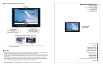
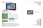
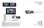
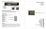
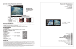
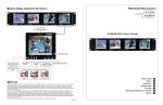
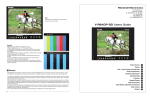
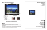
10 Switch Settings, Functions and Indicators
Marshall Electronics
Tally Indicators
1910 East Maple Ave.
El Segundo, CA 90245
Tel.: 800-800-6608 • Fax: 310-333-0688
www.LCDRacks.com
Email: [email protected]
V-R65P-HD
Users Guide
Power On/Off
selection switch
Illuminates Red
when power is applied.
Turns Green when
monitor is switched on
Input Source selectors.
Selected source will
illuminate the indicator.
Flashing indicates
no signal present.
Component button
toggles:
Tap 1-YPrPb interlace,
Tap 2-YprPb Progressive,
Tap 3-VGA
Function Control Table
BUTTON
FUNCTION
BARS
Bars On/Off
(overrides video input)
BARS + ZOOM
Sharpness
(Toggles 4 Settings plus off)
MARK
Frame Aspect Shaded
Overlay
Tap Once-14:9
Tap Twice –13:9
Tap Thrice – 4:3
Tap 4 times –1.85:1
Tap 5 times – 2.35:1
Hold MARK for
2 seconds
Center & Safe area display
(Toggle On/Off)
ZOOM
Tap once – Mono
Tap Twice-Zoom Mono
Tap Thrice-Zoom Color
Tap four times-Normal
Hold BARS for
2 seconds
Blue only display
(Toggle On/Off)
Hold ZOOM for
2 seconds
16:9/4:3 aspect toggle
Screen adjustments
TINT adjust is not
available for PAL, Digital,
or Component signal
standards.
11 Warranty
Marshall Electronics warranties to the first consumer, that this V-R65P-HD portable monitor will, under normal use, be free from defects in workmanship and materials, when received in its original container, for a period of one year from the purchase date.
This warranty is extended to the first consumer only and proof of purchase is necessary to honor the warranty. If there is no proof of purchase provided with a warranty claim, Marshall Electronics reserves the right, not to honor the warranty set forth above. Therefore, labor and parts may be
charged to you.
This warranty does not apply to product exterior and cosmetics. Misuse, abnormal service or handling, improper alterations or modifications in
design or construction, voids this warranty. No sales personnel of the seller, nor any other person is authorized to make any warranties other than
those described above, or to extend the duration of any warranties on behalf of Marshall Electronics, beyond the time period described above.
Prior to any warranty repair, a Return Material Authorization (RMA) must be issued by the dealer/distributor that sold the V-R65P-HD to the original
user. Returned products must be clearly identified with the RMA number on the outside packaging.
Marshall Electronics reserves the right to repair or replace warranted products after evaluation by the factory repair depot.
Due to constant effort to improve products and product features, specifications may change without notice.
© Marshall Electronics
• 1910 East Maple Avenue • El Segundo, CA • Product and features subject to change
Product Overview
1
Features
2
Standard Accessories
3
Optional Accessories
4
Electrical Specifications
5
Mechanical Specification
6
Faceplate Cleaning
7
Operational Setup
8
Input Connectors
9
Switch Settings, Functions and Indicators 10
Warranty 11
TABLE-1
1 Product Overview
The V-R65P-HD is the perfect solution for HDTV or SD Wide Screen portable monitor applications. The unit offers
a flexible input configuration without the need of special adapter boxes. There are Standard inputs with active loop
through on each connection for HDSDI/SDI (SMPTE259M, SMPTE-292M) and composite video with PAL/NTSC
automatic recognition. An HD-15 multiformat connector for HD or SD analog component signals (SMPTE274M) is
also included. For computer graphic applications, the HD-15 connector is also used for scalable XGA to SXGA input.
Additional features include Monochrome, Zoom function for camera focus, 6 Frame Marker Overlays, center and safe
area marks plus Blue only display for use with SMPTE color bars.
Analog Component High Definition Video, Standard Definition Video or Computer VGA to UGA Connector - Pin Assignment
Type
HD Analog color difference
YPbPr
SD Analog color difference
Y, R-Y, B-Y
HD or SD Analog RGB
(Sync on Green)
VGA to UXGA
Pin1
Pr
R-Y
Red
Red
Pin 2
Y
Y
Green
Green
Pin3
Pb
B-Y
Blue
Blue
Pin6
Ground
Ground
Ground
Ground
Pin7
Ground
Ground
Ground
Ground
Pin8
Ground
Ground
Ground
Ground
Pin4
Pin5
2 Features
Standard Inputs
Display Multiple Screen Formats and Frame Rates
On Screen Frame Markers in 16:9 Mode
B&W (Mono) Mode
Blue Screen
Zoom Function
Built-in color bars
Sharpness Function
Tally
•
•
•
•
•
•
•
•
•
•
•
•
•
HDSDI (SMPTE292M/296M) with active loop through
SDI (SMPTE259M) (ITU-R BT.601-5)
Component Analog HD/SD (SMPTE274M) (SMPTE/EBU N-10)
Composite Video PAL/NTSC (ITU-R BT.470/SMPTE170M) with loop through
SVGA, XGA, SXGA with Automatic Scaling
525 –60i / 625 - 50i (Interlaced)
480 x 640 - 23.973P, 24P, 25P, 29.97P, 30P, 59.94P, 60P (Progressive)
720 x 1280 - - 23.973P, 24P, 25P, 29.97P, 30P, 59.94P, 60P (Progressive)
1035 x 1920 - 59.94i, 60i (Interlaced)
1080 x 1920 – 50i, 59.94i, 60i / 23.973Psf, 24Psf, 25Psf, 29.97Psf, 30Psf
Center Frame Quad and Safe Area Mark(White and Black Super Imposed)
4:3, 13:9, 14:9, 15:9, 1.85:1, 2.35:1 Shaded Overlay
Luma only checks for green screen shadows, on set lighting, etc.
Pin9
Pin10
Pin11
Pin12
Pin13
Pin14
H Sync
Pin15
V Sync
TABLE-2
• Use for adjustment to SMPTE color Bars
• Use for screen center camera focus. Zoom available for all inputs
• For screen set up on VCR/DDR playback
• For enhanced viewing of interlaced images
• Three LEDs (Red, Green, Amber) produce 7 different tally indications
3 Standard Accessories
Accessories Supplied with the V-R65-HD:
1. 6 foot Component signals
hook up cable
2. “Brick” type 12vdc power
supply 5.0 Amp Max
3. Users manual
YPbPr/RGB Analog Component and Composite Video Systems Supported by the V-R65P-HD
Signal
Frames per Second
Aspect
Active Lines
Scanning Method
525-60i
30/29.97
4:3/16:9
483
Interlaced
625-50i
25
4:3/16:9
576
Interlaced
640 x 480P
60/59.94/30/29.97/24/23.97
4:3
483
Progressive
720x480P
60/59.94
16:9
483
Progressive
1280x720P
60/59.94
16:9
720
Progressive
1920x1035
60/59.94
4:3/16:9
1035
Interlaced
1920x1080
60/59.94/50
4:3/16:9
1080
Interlaced
1920x1080
30/29.97
4:3/16:9
1080
Progressive
Computer Display Systems Supported by the V-R65P-HD
Standard
4 Optional Accessories
Stand
V-LCD4-ST
Use for table top mount
Resolution (Frequency)
SVGA
800 x 600 (60 , 75 ,85 Hz)
XGA
1024 x 768 (60 ,75 ,85 Hz)
SXGA
1280 x 960 (60 Hz)
SXGA
1280 x 1024 (60 Hz)
TABLE-3
HDSDI/SDI Input BNC Connector Signals
Signal
Camera Hot Shoe Mount
Sun Hood
V-LCD4-MT
Attaches monitor to camera
V-H700P
Use for viewing in bright lighting or outdoors
Aspect
Active Lines
Scanning Method
Data Rate
525-60i
30/29.97
4:3/16:9
483
Interlaced
270Mb/s
625-50i
25
4:3/16:9
576
Interlaced
270Mb/s
640 x 480P
60/59.94/30/29.97/24/23.97
4:3
483
Progressive
540Mb/s
720x480P
60/59.94/30/29.97/24/23.97
16:9
483
Progressive
540Mb/s
1280x720P
60/59.94/30/29.97/24/23.97
16:9
720
Progressive
1.5Gb/s
1920x1035
60/59.94
4:3/16:9
1035
Interlaced
1.5Gb/s
1920x1080
60/59.94/50
4:3/16:9
1080
Interlaced
1.5Gb/s
1920x1080
30/29.97/25/24/23.97
4:3/16:9
1080
Progressive
1.5Gb/s
TABLE-4
Analog Composite Input BNC Connector Signals
Signal
V-R65P-HD Users Guide
Frames per Second
Frames per Second
Aspect
Active Lines
Scanning Method
Data Rate
525-60i
30/29.97
4:3/16:9
483
Interlaced
270Mb/s
625-50i
25
4:3/16:9
576
Interlaced
270Mb/s
Marshall Electronics
Optional Accessories (continued)
8 Operational Setup
1. Unpack the V-R65P-HD and accompanying V-PS12-5V-1 power supply. Physically inspect for any damage that may
have occurred during shipping. Should there be any damage, immediately contact Marshall Electronics at 800-8006608. If you are not located within the continental united states call +1 310-333-0606.
2. Connect required cables for signal input and output.
Please note that power must be applied to the V-R65P-HD for the HDSDI/SDI and composite outputs to be
activated. All BNC connectors should be rated for 75Ω.
3. Plug the V-PS12-5V-1 power supply into the A.C. source
Please note that power can be supplied from a variety of DC sources, such as batteries or Vehicle power.
Input power range is 10.7 to 15 Volt D.C. In operation, the V-R65P-HD will draw approx. 0.8 amp.
Attach twist lock power connection from V-PS12-5V-1 power supply to the back of the unit.
V-R65-RPS
Rack-mount kit A
Rack-mount kit B
V-R65-1M
V-R65-2M
Component input cable
RGB-5HD15-X
Power Adapter Cable
V-PAC-D
Power Adapter Cable
V-PAC-XLR
Use with 4 Pin XLR connections
Mount for IDX Batteries
V-R65-BA
Attaches to V-R65P-HD monitor
Sequential 2 channel
charger
IDX-VL-2Plus
2-channel sequential charger with a built-in 60W power supply. Charges 2 ENDURA E series batteries in fewer than 5
hours. One 10’ XLR cable included.only 2 lbs
Sequential 4 channel
charger
IDX-VL-4
Economically charges 4 ENDURA E series batteries in under
6 hours using Full Power Charge (FPC) method
Simultaneous 4 channel
charger
IDX-VL-4S
Charges 4 ENDURA E series batteries in 2.5 hours or less
55 W Lithium Battery
IDX-E50S
4. Turn on the V-R65P-HD by depressing the power switch located on the front of the unit.
9 Input Connectors
Use to replace damaged or scratched protective
cover for screen
Replacement
Protection Screen
(Image not available)
(Image not available)
Single monitor mount for 19” rack
Dual monitor mount for 19” rack
HD-15 to BNC break out cable
(X = Length in feet 6, 10, 15, 20)
Use with Anton Bauer D-type connection
* Tally lamps active when connected to ground
Tally IN DB-15 Female
HDSDI or SDI in.
270Mbs to 1.5Gbs
Automatically
terminates to 75Ω
Refer to Table 3
for signal types
Composite Video IN
NTSC/PAL
Automatically
terminates
to 75Ω
Component Video
or VGA INPUT
HD-15 Female refer
to Table 1 for signal
pin outs and Table 2
for Signal Types
Pin1- Green
Pin2- Red
Pin3-Amber
Pin4 Gnd Pin5Pin6Pin7-
Pin8Pin 9Pin10Pin11Pin12Pin13Pin14Pin15-
V-Mount battery pack with 3 LED power Indicator
Re-Clocked
HDSDI/SDI Output.
Signal in equals
signal out
Active
Composite
Output
10.7 to 15 VDC
V-PS12-5V-1 power supply is
included
Left Pin - Pos. Right Pin- Neg
55 W Lithium Battery
with Power Link
IDX-E50
82 W Lithium Battery
IDX-E80S
82 W Lithium Battery
with Power Link
IDX-E80
V-Mount Battery Pack with PowerLink includes accurate
Power Status Display and supports Digi-View
V-Mount battery pack with 3 LED power Indicator
V-R65P-HD Users Guide
V-Mount Battery Pack with PowerLink includes accurate
Power Status Display and supports Digi-View
Marshall Electronics
V-R65P-HD shown with side mount configuration of V-R65-BA adaptor
and IDX-E50S battery installed
5 Electrical Specifications
Display (Viewing Area)
Viewing Angles
Resolution (RGB Dots)
Contrast Ratio
Dot Pitch
Pixel Response
Brightness
System
IDX-E50S
V-R65-BA
Inputs
6.5” (5.67”H × 3.10”V) (144.0mm x 78.24mm)
130°H x 120°V
800H x RGBx480V (1.2 million pixels)
400:1
0.163 mm
<25ms
400 cd/m²
NTSC/PAL auto recognition for composite video
Composite with loop (BNC)
HDSDI/SDI with re-clocked output (BNC)
Multiple Analog Format HD-15
6 Mechanical Specification
V-R65P-HD shown with V-LCD4-MT camera hot shoe mount attached plus rear mount
configuration of V-R65-BA adaptor and IDX-E50S battery
Dimensions
Approx. Weight
Power Consumption
Display Viewing Area
7.25”W x 4.25”H x 2.5”D
3 lbs
12VDC, 5.0 Amps max - UL Class 2 (supply included)
6.5” (5.67”H x 3.10”V) (144.0mm x 78.24mm)
7 Faceplate Cleaning
When cleaning the faceplate it is very important to use non-abrasive and ammonia free cleaning agents and a clean
micro fiber clothe, or cheese clothe. Do not use paper towels. Paper towel fibers are too coarse and will scratch the
surface of the Plexiglas faceplate. Paper towels may also leave streaks on the surface.
Antistatic and fingerprint resistant Plexiglas cleaning agents are recommended.
IDX-E50S
V-R65-BA
V-LCD4-MT
V-R65P-HD shown with V-H700P hood attached plus side mount configuration of
V-R65-BA adaptor and IDX-E50S battery
V-R65P-HD Users Guide
Marshall Electronics