1
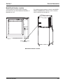
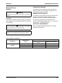
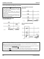
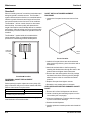
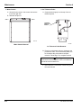
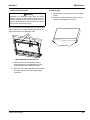
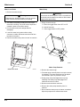
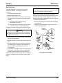
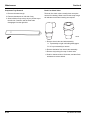
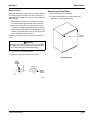
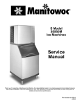
S0850M Model
Ice Machines
Installation
Use and Care
Manual
Thank you for selecting a Manitowoc Ice
Machine, the dependability leader in ice
making equipment and related products.
With proper installation, care and
maintenance, your new Manitowoc Ice
Machine will provide you with many years of
reliable and economical performance.
Part Number 80-1560-3
05/2005
Safety Notices
Procedural Notices
As you work on an S Model Series Ice Machine, be sure
to pay close attention to the safety notices in this
manual. Disregarding the notices may lead to serious
injury and/or damage to the ice machine.
As you work on an S Model Series Ice Machine, be sure
to read the procedural notices in this manual. These
notices supply helpful information which may assist you
as you work.
Throughout this manual, you will see the following types
of safety notices:
Throughout this manual, you will see the following types
of procedural notices:
! Warning
PERSONAL INJURY POTENTIAL
Do not operate equipment that has been misused,
abused, neglected, damaged, or altered/modified
from that of original manufactured specifications.
! Warning
Text in a Warning box alerts you to a potential
personal injury situation. Be sure to read the
Warning statement before proceeding, and work
carefully.
Important
Text in an Important box provides you with
information that may help you perform a procedure
more efficiently. Disregarding this information will
not cause damage or injury, but it may slow you
down as you work.
NOTE: Text set off as a Note provides you with simple,
but useful, extra information about the procedure you
are performing.
Read These Before Proceeding:
! Caution
! Caution
Text in a Caution box alerts you to a situation in
which you could damage the ice machine. Be sure
to read the Caution statement before proceeding,
and work carefully.
Proper installation, care and maintenance are
essential for maximum ice production and troublefree operation of your Manitowoc Ice Machine.
Read and understand this manual. It contains
valuable care and maintenance information. If you
encounter problems not covered by this manual, do
not proceed, contact Manitowoc Ice, Inc. We will be
happy to provide assistance.
Important
Routine adjustments and maintenance procedures
outlined in this manual are not covered by the
warranty.
! Warning
PERSONAL INJURY POTENTIAL
Remove all ice machine panels before lifting and
installing.
Table of Contents (continued)
Section 1
General Information
Model Numbers . . . . . . . . . . . . . . . . . . . . . . . . . . . . . . . . . . . . . . . . . . . . . . . . .
How to Read a Model Number . . . . . . . . . . . . . . . . . . . . . . . . . . . . . . . . . . . . .
Ice Cube Sizes . . . . . . . . . . . . . . . . . . . . . . . . . . . . . . . . . . . . . . . . . . . . . . . . . .
Accessories . . . . . . . . . . . . . . . . . . . . . . . . . . . . . . . . . . . . . . . . . . . . . . . . . . . .
Bin Caster . . . . . . . . . . . . . . . . . . . . . . . . . . . . . . . . . . . . . . . . . . . . . . . . . .
Ice Bagger . . . . . . . . . . . . . . . . . . . . . . . . . . . . . . . . . . . . . . . . . . . . . . . . . .
Guardian Sachet Packets . . . . . . . . . . . . . . . . . . . . . . . . . . . . . . . . . . . . . .
Arctic Pure Water Filter System . . . . . . . . . . . . . . . . . . . . . . . . . . . . . . . . .
Manitowoc Cleaner and Sanitizer . . . . . . . . . . . . . . . . . . . . . . . . . . . . . . . .
AuCS® Automatic Cleaning System . . . . . . . . . . . . . . . . . . . . . . . . . . . . . .
Dispenser . . . . . . . . . . . . . . . . . . . . . . . . . . . . . . . . . . . . . . . . . . . . . . . . . .
Model/Serial Number Location . . . . . . . . . . . . . . . . . . . . . . . . . . . . . . . . . . . . .
Owner Warranty Registration Card . . . . . . . . . . . . . . . . . . . . . . . . . . . . . . . . .
General . . . . . . . . . . . . . . . . . . . . . . . . . . . . . . . . . . . . . . . . . . . . . . . . . . . .
Warranty Coverage . . . . . . . . . . . . . . . . . . . . . . . . . . . . . . . . . . . . . . . . . . . . . .
General . . . . . . . . . . . . . . . . . . . . . . . . . . . . . . . . . . . . . . . . . . . . . . . . . . . .
Parts . . . . . . . . . . . . . . . . . . . . . . . . . . . . . . . . . . . . . . . . . . . . . . . . . . . . . .
Labor . . . . . . . . . . . . . . . . . . . . . . . . . . . . . . . . . . . . . . . . . . . . . . . . . . . . . .
Exclusions . . . . . . . . . . . . . . . . . . . . . . . . . . . . . . . . . . . . . . . . . . . . . . . . . .
Authorized Warranty Service . . . . . . . . . . . . . . . . . . . . . . . . . . . . . . . . . . .
1-1
1-1
1-1
1-2
1-2
1-2
1-2
1-2
1-2
1-2
1-2
1-3
1-4
1-4
1-4
1-4
1-4
1-4
1-4
1-4
Section 2
Installation Instructions
General . . . . . . . . . . . . . . . . . . . . . . . . . . . . . . . . . . . . . . . . . . . . . . . . . . . . . . . .
Ice Machine Dimensions . . . . . . . . . . . . . . . . . . . . . . . . . . . . . . . . . . . . . . . . . .
s0850M Ice Machines . . . . . . . . . . . . . . . . . . . . . . . . . . . . . . . . . . . . . . . . .
Location of Ice Machine . . . . . . . . . . . . . . . . . . . . . . . . . . . . . . . . . . . . . . . . . .
Ice Machine Heat of Rejection . . . . . . . . . . . . . . . . . . . . . . . . . . . . . . . . . . . . .
Electrical Service . . . . . . . . . . . . . . . . . . . . . . . . . . . . . . . . . . . . . . . . . . . . . . . .
General . . . . . . . . . . . . . . . . . . . . . . . . . . . . . . . . . . . . . . . . . . . . . . . . . . . .
Voltage . . . . . . . . . . . . . . . . . . . . . . . . . . . . . . . . . . . . . . . . . . . . . . . . . . . .
Fuse/Circuit Breaker . . . . . . . . . . . . . . . . . . . . . . . . . . . . . . . . . . . . . . . . . .
Minimum Circuit Ampacity . . . . . . . . . . . . . . . . . . . . . . . . . . . . . . . . . . . . .
Electrical Requirements . . . . . . . . . . . . . . . . . . . . . . . . . . . . . . . . . . . . . . .
Self-Contained Electrical Wiring Connections . . . . . . . . . . . . . . . . . . . . . . . .
Self Contained Ice Machine
115/1/60 or 208-230/1/60 . . . . . . . . . . . . . . . . . . . . . . . . . . . . . . . . . . . . . .
Self Contained Ice Machine
208-230/3/60 . . . . . . . . . . . . . . . . . . . . . . . . . . . . . . . . . . . . . . . . . . . . . . . .
Self Contained Ice Machine
230/1/50 . . . . . . . . . . . . . . . . . . . . . . . . . . . . . . . . . . . . . . . . . . . . . . . . . . .
For United Kingdom Only . . . . . . . . . . . . . . . . . . . . . . . . . . . . . . . . . . . . . . . . .
Water Supply and Drain Requirements . . . . . . . . . . . . . . . . . . . . . . . . . . . . . .
Water Supply . . . . . . . . . . . . . . . . . . . . . . . . . . . . . . . . . . . . . . . . . . . . . . .
Water Inlet Lines . . . . . . . . . . . . . . . . . . . . . . . . . . . . . . . . . . . . . . . . . . . . .
Drain Connections . . . . . . . . . . . . . . . . . . . . . . . . . . . . . . . . . . . . . . . . . . .
Cooling Tower Applications
(Water-Cooled Models) . . . . . . . . . . . . . . . . . . . . . . . . . . . . . . . . . . . . . . . . . . .
Water Supply and Drain Line Sizing/Connections . . . . . . . . . . . . . . . . . . .
Installation Check List . . . . . . . . . . . . . . . . . . . . . . . . . . . . . . . . . . . . . . . . . . . .
Before Starting the Ice Machine . . . . . . . . . . . . . . . . . . . . . . . . . . . . . . . . . . . .
Part No. 80-1560-3
2-1
2-1
2-1
2-2
2-2
2-3
2-3
2-3
2-3
2-3
2-3
2-4
2-4
2-4
2-4
2-4
2-5
2-5
2-5
2-5
2-5
2-6
2-7
2-8
1
Table of Contents (continued)
Section 3
Ice Machine Operation
Component Identification . . . . . . . . . . . . . . . . . . . . . . . . . . . . . . . . . . . . . . . . .
Sequence Of Operation . . . . . . . . . . . . . . . . . . . . . . . . . . . . . . . . . . . . . . . . . . .
Initial Start-Up or Start-Up After Automatic Shut-Off . . . . . . . . . . . . . . . . . .
Freeze Sequence . . . . . . . . . . . . . . . . . . . . . . . . . . . . . . . . . . . . . . . . . . . .
Harvest Sequence . . . . . . . . . . . . . . . . . . . . . . . . . . . . . . . . . . . . . . . . . . . .
Automatic Shut-Off . . . . . . . . . . . . . . . . . . . . . . . . . . . . . . . . . . . . . . . . . . .
Safety Timers . . . . . . . . . . . . . . . . . . . . . . . . . . . . . . . . . . . . . . . . . . . . . . . .
Warm Water Rinse Cycle . . . . . . . . . . . . . . . . . . . . . . . . . . . . . . . . . . . . . .
Operational Checks . . . . . . . . . . . . . . . . . . . . . . . . . . . . . . . . . . . . . . . . . . . . . .
General . . . . . . . . . . . . . . . . . . . . . . . . . . . . . . . . . . . . . . . . . . . . . . . . . . . .
Water Level . . . . . . . . . . . . . . . . . . . . . . . . . . . . . . . . . . . . . . . . . . . . . . . . .
Ice Thickness Check . . . . . . . . . . . . . . . . . . . . . . . . . . . . . . . . . . . . . . . . . .
Harvest Sequence Water Purge . . . . . . . . . . . . . . . . . . . . . . . . . . . . . . . . .
3-1
3-2
3-2
3-2
3-3
3-3
3-3
3-3
3-4
3-4
3-4
3-4
3-5
General . . . . . . . . . . . . . . . . . . . . . . . . . . . . . . . . . . . . . . . . . . . . . . . . . . . . . . . .
Ice Machine Inspection . . . . . . . . . . . . . . . . . . . . . . . . . . . . . . . . . . . . . . . . . . .
Exterior Cleaning . . . . . . . . . . . . . . . . . . . . . . . . . . . . . . . . . . . . . . . . . . . . . . . .
Water-Cooled Condenser
and Water Regulating Valve . . . . . . . . . . . . . . . . . . . . . . . . . . . . . . . . . . . . . . .
AlphaSan . . . . . . . . . . . . . . . . . . . . . . . . . . . . . . . . . . . . . . . . . . . . . . . . . . . . . . .
Guardianf . . . . . . . . . . . . . . . . . . . . . . . . . . . . . . . . . . . . . . . . . . . . . . . . . . . . . . .
Guardian Sachet Replacement Frequency . . . . . . . . . . . . . . . . . . . . . . . . .
Sachet Replacement Procedure . . . . . . . . . . . . . . . . . . . . . . . . . . . . . . . . .
Clean Up Procedure for Damaged Sachet Packet . . . . . . . . . . . . . . . . . . .
Interior Cleaning and Sanitizing . . . . . . . . . . . . . . . . . . . . . . . . . . . . . . . . . . . .
General . . . . . . . . . . . . . . . . . . . . . . . . . . . . . . . . . . . . . . . . . . . . . . . . . . . .
Cleaning Procedure . . . . . . . . . . . . . . . . . . . . . . . . . . . . . . . . . . . . . . . . . . .
Sanitizing Procedure . . . . . . . . . . . . . . . . . . . . . . . . . . . . . . . . . . . . . . . . . .
Removal of Parts For Cleaning/Sanitizing . . . . . . . . . . . . . . . . . . . . . . . . . .
Removing the Front Panels . . . . . . . . . . . . . . . . . . . . . . . . . . . . . . . . . . . . . . . .
Removal from Service/Winterization . . . . . . . . . . . . . . . . . . . . . . . . . . . . . . . .
General . . . . . . . . . . . . . . . . . . . . . . . . . . . . . . . . . . . . . . . . . . . . . . . . . . . .
Self-Contained Air-Cooled Ice Machines . . . . . . . . . . . . . . . . . . . . . . . . . . .
Water-Cooled Ice Machines . . . . . . . . . . . . . . . . . . . . . . . . . . . . . . . . . . . .
AuCS“ Accessory . . . . . . . . . . . . . . . . . . . . . . . . . . . . . . . . . . . . . . . . . . . . .
4-1
4-1
4-1
Section 4
Maintenance
4-1
4-1
4-2
4-2
4-2
4-2
4-3
4-3
4-3
4-4
4-5
4-11
4-12
4-12
4-12
4-12
4-12
Section 5
Before Calling For Service
Checklist . . . . . . . . . . . . . . . . . . . . . . . . . . . . . . . . . . . . . . . . . . . . . . . . . . . . . . .
Safety Limit Feature . . . . . . . . . . . . . . . . . . . . . . . . . . . . . . . . . . . . . . . . . . . . . .
2
5-1
5-2
Part No. 80-1560-3
Section 1
General Information
Section 1
General Information
Model Numbers
How to Read a Model Number
This manual covers the following models:
# CUBE SIZE
Self-Contained
Water-Cooled
SD0853WM
SY0855WM
3
5
PERSONAL INJURY POTENTIAL
Do not operate equipment that has been misused,
abused, neglected, damaged, or altered/modified
from that of original manufactured specifications.
DICE
WATER-COOLED
HALF-DICE WATER-COOLED
MARlNE MODEL
NOTE: Model numbers ending in 3 indicate a 3-phase
unit. Example: SY0855M3
! Warning
CONDENSER TYPE
S Y 0855 W M
ICE MACHINE
MODEL
ICE CUBE SIZE
D DICE
Y HALF DICE
ICE MACHINE
SERIES
CONDENSER TYPE
W SELF-CONTAINEDWATER-COOLED
Ice Cube Sizes
! Warning
PERSONAL INJURY POTENTIAL
Remove all ice machine panels before lifting and
installing.
Dice
Half Dice
7/8" x 7/8" x 7/8"
3/8" x 1-1/8" x 7/8"
2.22 x 2.22 x 2.22 cm 0.95 x 2.86 x 2.22 cm
Part Number 80-1560-3
1-1
General Information
Section 1
Accessories
MANITOWOC CLEANER AND SANITIZER
Contact your Manitowoc distributor for these optional
accessories:
Manitowoc Ice Machine Cleaner and Sanitizer are
available in convenient 16 oz. (473 ml) bottles. These
are the only cleaner and sanitizer approved for use with
Manitowoc products.
BIN CASTER
Replaces standard legs.
ICE BAGGER
Maximize profits from bagged ice sales with this
convenient accessory. This sturdy unit rests on the bin
door frame, and adapts for left or right side filling.
GUARDIAN™ SACHET PACKETS
Guardian sachet packets release chlorine dioxide on a
controlled basis to inhibit the growth of bacteria and
slime.
Guardian sachet packets are available through your
local Manitowoc Ice Machine dealer.
ARCTIC PURE™ WATER FILTER SYSTEM
Engineered specifically for Manitowoc ice machines,
This water filter is an efficient, dependable, and
affordable method of inhibiting scale formation, filtering
sediment, and removing chlorine taste and odor.
1-2
Cleaner Part Number
16 ounce Bottle - 94-0546-3
AuCS®-SO - 94-0546-3
AuCS®-SI - 40-1325-3
Sanitizer Part Number
16 ounce Bottle - 94-0565-3
AuCS®-SO - 94-0565-3
AuCS®-SI - 40-1236-3
AUCS® AUTOMATIC CLEANING SYSTEM
This accessory reduces equipment cleaning expense.
The AuCS® accessory monitors ice making cycles and
initiates cleaning procedures automatically.
DISPENSER
A counter-top dispenser is ideal for cafeterias and many
types of self-service facilities. Manitowoc auto-fill, floorstanding ice dispensers meet the strict sanitary
requirements of the food service, lodging and health
care industries.
Part Number 80-1560-3
Section 1
General Information
Model/Serial Number Location
These numbers are required when requesting
information from your local Manitowoc distributor, or
Manitowoc Ice, Inc.
The model and serial number are listed on the MODEL/
SERIAL NUMBER DECAL affixed to the ice machine,
remote condenser and storage bin.
SV13147
MODEL/SERIAL PLATE
LOCATION
Model/Serial Number Location
Part Number 80-1560-3
1-3
General Information
Section 1
Owner Warranty Registration Card
GENERAL
EXCLUSIONS
The packet containing this manual also includes
warranty information. Warranty coverage begins the day
your new ice machine is installed.
The following items are not included in the ice machine’s
warranty coverage:
Important
Complete and mail the OWNER WARRANTY
REGISTARATION CARD as soon as possible to
validate the installation date.
If you do not return your OWNER WARRANTY
REGISTRATION CARD, Manitowoc will use the date of
sale to the Manitowoc Distributor as the first day of
warranty coverage for your new ice machine.
Warranty Coverage
GENERAL
The following Warranty outline is provided for your
convenience. For a detailed explanation, read the
warranty bond shipped with each product.
Contact your local Manitowoc Distributor, Manitowoc Ice,
Inc. or visit our website at www.manitowocice.com if you
need further warranty information.
Important
This product is intended exclusively for commercial
application. No warranty is extended for personal,
family, or household purposes.
PARTS
1. Manitowoc warrants the ice machine against defects
in materials and workmanship, under normal use
and service for three (3) years from the date of
original installation.
2. The evaporator and compressor are covered by an
additional two (2) year (five years total) warranty
beginning on the date of the original installation.
LABOR
1. Labor required to repair or replace defective
components is covered for three (3) years from the
date of original installation.
2. The evaporator is covered by an additional two (2)
year (five years total) labor warranty beginning on
the date of the original installation.
1-4
1. Normal maintenance, adjustments and cleaning.
2. Repairs due to unauthorized modifications to the ice
machine or use of non-standard parts without prior
written approval from Manitowoc Ice, Inc.
3. Damage caused by improper installation of the ice
machine, electrical supply, water supply or drainage,
or damage caused by floods, storms, or other acts of
God.
4. Premium labor rates due to holidays, overtime,
etc.; travel time; flat rate service call charges;
mileage and miscellaneous tools and material
charges not listed on the payment schedule.
Additional labor charges resulting from the
inaccessibility of equipment are also excluded.
5. Parts or assemblies subjected to misuse, abuse,
neglect or accidents.
6. Damage or problems caused by installation,
cleaning and/or maintenance procedures
inconsistent with the technical instructions provided
in this manual.
7. This product is intended exclusively for commercial
application. No warranty is extended for personal,
family, or household purposes.
AUTHORIZED WARRANTY SERVICE
To comply with the provisions of the warranty, a
refrigeration service company qualified and authorized
by a Manitowoc distributor, or a Contracted Service
Representative must perform the warranty repair.
NOTE: If the dealer you purchased the ice machine from
is not authorized to perform warranty service, contact
your Manitowoc distributor or Manitowoc Ice, Inc. for the
name of the nearest authorized service representative.
Service Calls
Normal maintenance, adjustments and cleaning as
outlined in this manual are not covered by the warranty.
If you have followed the procedures listed on page 5-1 of
this manual, and the ice machine still does not perform
properly, call your authorized service company.
Part Number 80-1560-3
Section 2
Installation Instructions
Section 2
Installation Instructions
General
These instructions are provided to assist the qualified
installer. Check your local Yellow Pages for the name of
the nearest Manitowoc distributor, or call Manitowoc Ice,
Inc. for information regarding start-up services.
Important
Failure to follow these installation guidelines may
affect warranty coverage.
Ice Machine Dimensions
S0850M ICE MACHINES
ELECTRICAL
2.20" (5.58cm)
H
A
B
C
E
1.81"
(4.59cm)
2.61"
(6.62cm)
AUCS
CONNECTIONS
F
5.06" (12.85cm)
4.21" (10.69cm)
2.85" (7.30cm)
1.06 (2.7cm)
6.68" (16.96cm)
CONDENSER WATER
OUTLET 1/2"FPT
(Water-Cooled Only)
D
AUXILLARY BASE
DRAIN 1/2"CPVC
SOCKET
8.49" (21.56cm)
25.52" (64.82cm)
SV3143
W
WATER INLET
3/8"FPT
CONDENSER WATER
INLET 3/8"FPT
(Water-Cooled Only)
SV3143B
DRAIN 1/2"NPTF
Width, Depth, and Height Dimensions
Ice Machine
S850M
Dimension W
30 in. (76.2 cm)
Dimension D
24.50 in. (62.2 cm)
Dimension H
26.5 in (67.3 cm)
Electrical and AuCS Dimensions
Ice Machine
S850M
Electrical
Dimension A
Dimension B
23.82 in (60.5 cm) 22.32 in (56.69 cm)
Part Number 80-1560-3
Dimension C
8.5 in (21.6 cm)
AuCS
Dimension E
8.5 in (21.6 cm)
Dimension F
6.5 in (16.5 cm)
2-1
Installation Instructions
Section 2
Location of Ice Machine
Ice Machine Heat of Rejection
The location selected for the ice machine must meet the
following criteria. If any of these criteria are not met,
select another location.
•
The location must be free of airborne and other
contaminants.
•
The air temperature must be at least 35°F (1.6°C),
but must not exceed 110°F (43.4°C).
•
The location must not be near heat-generating
equipment or in direct sunlight.
•
The location must not obstruct air flow through or
around the ice machine. Refer to the chart below for
clearance requirements.
S0850M
Top/Sides
Back
Water-Cooled*
8" (20.3 cm)
5" (12.7 cm)
*There is no minimum clearance required. This value is
recommended for efficient operation and servicing only.
Series
Ice Machine
S0850M
Heat of Rejection
Air Conditioning
Peak
12,000
18,000
B.T.U./Hour
Because the heat of rejection varies during the ice making cycle,
the figure shown is an average.
Ice machines, like other refrigeration equipment, reject
heat through the condenser. It is helpful to know the
amount of heat rejected by the ice machine when sizing
air conditioning equipment where self-contained aircooled ice machines are installed.
This information is also necessary when evaluating the
benefits of using water-cooled or remote condensers to
reduce air conditioning loads. The amount of heat added
to an air conditioned environment by an ice machine
using a water-cooled or remote condenser is negligible.
Knowing the amount of heat rejected is also important
when sizing a cooling tower for a water-cooled
condenser. Use the peak figure for sizing the cooling
tower.
! Caution
The ice machine must be protected if it will be
subjected to temperatures below 32°F (0°C).
Failure caused by exposure to freezing
temperatures is not covered by the warranty. See
“Removal from Service/Winterization”.
2-2
Part Number 80-1560-3
Section 2
Installation Instructions
Electrical Service
FUSE/CIRCUIT BREAKER
GENERAL
A separate fuse/circuit breaker must be provided for
each ice machine. Circuit breakers must be H.A.C.R.
rated (does not apply in Canada).
! Warning
All wiring must conform to local, state and national
codes.
MINIMUM CIRCUIT AMPACITY
VOLTAGE
The minimum circuit ampacity is used to help select the
wire size of the electrical supply. (Minimum circuit
ampacity is not the ice machine’s running amp load.)
The maximum allowable voltage variation is ±10% of the
rated voltage at ice machine start-up (when the electrical
load is highest).
The wire size (or gauge) is also dependent upon
location, materials used, length of run, etc., so it must be
determined by a qualified electrician.
ELECTRICAL REQUIREMENTS
! Warning
The ice machine must be grounded in accordance
with national and local electrical codes.
Refer to Ice Machine Model/Serial Plate for voltage/
amperage specifications.
Important
Observe correct polarity of incoming line voltage.
S Series Marine Ice Machines
Ice Machine
Voltage Phase
Cycle
S0850M
208-230/1/60
208-230/3/60
230/1/50
Part Number 80-1560-3
Water Cooled
Maximum Fuse/Circuit
Minimum Circuit Amps
Breaker
20
10.3
15
6.8
20
9.1
2-3
Installation Instructions
Section 2
Self-Contained Electrical Wiring Connections
! Warning
These diagrams are not intended to show proper
wire routing, wire sizing, disconnects, etc., only the
correct wire connections.
SELF CONTAINED ICE MACHINE
208-230/3/60
All electrical work, including wire routing and
grounding, must conform to local, state and national
electrical codes.
Though wire nuts are shown in the drawings, the ice
machine field wiring connections may use either
wire nuts or screw terminals.
SELF CONTAINED ICE MACHINE
115/1/60 OR 208-230/1/60
L1
L1
L2
L2
L3
L3
GROUND
ICE MACHINE
CONNECTIONS
SV1190
L1
L1
N=115V
OR
L2=208-230V
GROUND
SV1258
GROUND
TO SEPARATE
FUSE/BREAKER
ICE MACHINE
CONNECTIONS
SELF CONTAINED ICE MACHINE
230/1/50
L1
GROUND
L1
TO SEPARATE
FUSE/BREAKER
N
N
GROUND
GROUND
ICE MACHINE
CONNECTIONS
SV1191
TO SEPARATE
FUSE/BREAKER.
DISCONNECT ALL
POLES.
For United Kingdom Only
As the colors of the wires in the mains lead of the appliance may not correspond with the colored markings
identifying the terminals in your plug, proceed as follows:
•
The wire which is colored green and yellow must be connected to the terminal in the plug which is marked with
the letter E or by the earth ground symbol
or colored green or green and yellow.
•
The wire colored blue must be connected to the terminal which is marked with the letter N or colored black.
•
The wire colored brown must be connected to the terminal which is marked with the letter L or colored red.
2-4
Part Number 80-1560-3
Section 2
Installation Instructions
Water Supply and Drain Requirements
DRAIN CONNECTIONS
WATER SUPPLY
Follow these guidelines when installing drain lines to
prevent drain water from flowing back into the ice
machine and storage bin:
Local water conditions may require treatment of the
water to inhibit scale formation, filter sediment, and
remove chlorine odor and taste.
Important
If you are installing a Manitowoc Arctic Pure™ water
filter system, refer to the Installation Instructions
supplied with the filter system for ice making water
inlet connections.
•
Drain lines must have a 1.5 inch drop per 5 feet of
run (2.5 cm per meter), and must not create traps.
•
The floor drain must be large enough to
accommodate drainage from all drains.
•
Run separate bin and ice machine drain lines.
Insulate them to prevent condensation.
•
Vent the bin and ice machine drain to the
atmosphere. Do not vent the condenser drain on
water-cooled models.
AIR GAP
An air gap is incorporated into the design of the ice
machine. Maximum water level is the top of the water
trough, which allows a minimum 1 inch air gap.
WATER INLET LINES
Follow these guidelines to install water inlet lines:
•
•
Do not connect the ice machine to a hot water
supply. Be sure all hot water restrictors installed for
other equipment are working. (Check valves on sink
faucets, dishwashers, etc.)
If water pressure exceeds the maximum
recommended pressure, obtain a water pressure
regulator from your Manitowoc distributor.
Cooling Tower Applications
(Water-Cooled Models)
A water cooling tower installation does not require
modification of the ice machine. The water regulator
valve for the condenser continues to control the
refrigeration discharge pressure.
It is necessary to know the amount of heat rejection, and
the pressure drop through the condenser and water
valves (inlet and outlet) when using a cooling tower on
an ice machine.
•
Water entering the condenser must not exceed 90°F
(32.2°C).
•
Install a water shut-off valve for both the ice making
and condenser water lines.
•
Water flow through the condenser must not exceed 5
gallons (19 liters) per minute.
•
Insulate water inlet lines to prevent condensation.
•
Allow for a pressure drop of 7 psi (48 kPA) between
the condenser water inlet and the outlet of the ice
machine.
•
Water exiting the condenser must not exceed 110°F
(43.3°C).
! Caution
Do not apply heat to water valve inlet fitting. This will
damage plastic valve body.
Part Number 80-1560-3
2-5
Installation Instructions
Section 2
WATER SUPPLY AND DRAIN LINE SIZING/CONNECTIONS
! Caution
Plumbing must conform to state and local codes.
Location
Water Temperature
Water Pressure
Ice Machine Fitting
Ice Making
Water Inlet
35°F (1.6°C) Min.
90°F (32.2°C) Max.
20 psi (137.9 kPA) Min.
80 psi (551.5 kPA) Max.
3/8" Female Pipe
Thread
Tubing Size Up to Ice
Machine Fitting
3/8" (.95 cm) minimum
inside diameter
Ice Making
Water Drain
---
---
1/2" Female
Pipe Thread
1/2" (1.27 cm) minimum
inside diameter
Condenser
Water Inlet
40°F (4.4°C) Min.
90°F (32.2°C) Max.
20 psi (137.9 kPA) Min.
150 psi (1034.2 kPA) Max.
Condenser
Water Drain
---
---
Bin Drain
---
---
3/8" Female Pipe Thread
1/2" Female
Pipe Thread
3/4" Female
Pipe Thread
1/2" (1.27 cm) minimum
inside diameter
3/4" (1.91 cm) minimum
inside diameter
3/8” FPT ICE MAKING WATER INLET FITTING,
PLASTIC FITTING ON OPPOSITE SIDE DO NOT
APPLY HEAT
ELECTRICAL ENTRANCE
18” (46 CM) VENT TUBE
3/8” FPT CONDENSER WATER INLET
(WATER COOLED UNITS ONLY
1/2” DRAIN CONNECTION
PLASTIC FITTING ON OPPOSITE
SIDE DO NOT APPLY HEAT
1/2” FPT CONDENSER WATER DRAIN
(WATER COOLED UNITS ONLY)
1/2” (1.3 CM) MIN
DRAIN ID
1/2” CPVC SOCKET AUXILLARY BASE
DRAIN
AIR GAP
DO NOT TRAP DRAIN LINE,
LEAVE AIR GAP BETWEEN
DRAIN TUBE AND DRAIN
OPEN, TRAPPED AND
VENTED DRAIN
SV3142
Typical Water Supply Drain Installation
2-6
Part Number 80-1560-3
Section 2
Installation Check List
Installation Instructions
Are the ice machine and bin drains vented?
Is the Ice Machine level?
Has all of the internal packing been removed?
Are all electrical leads free from contact with
refrigeration lines and moving equipment?
Have all of the electrical and water connections
been made?
Has the owner/operator been instructed
regarding maintenance and the use of
Manitowoc Cleaner and Sanitizer?
Has the supply voltage been tested and checked
against the rating on the nameplate?
Has the owner/operator completed the warranty
registration card?
Is there proper clearance around the ice machine
for air circulation?
Has the ice machine and bin been sanitized?
Has the ice machine been installed where
ambient temperatures will remain in the range of
35° - 110°F (1.6° - 43.3°C)?
Has the ice machine been installed where the
incoming water temperature will remain in the
range of 35° - 90°F (1.6° - 32.2°C)?
Is the toggle switch set to ice? (The toggle switch
is located directly behind the front panel).
Is the ice thickness control set correctly? (Refer
to Operational Checks to check/set the correct
ice bridge thickness).
Is there a separate drain for the water-cooled
condenser?
Part Number 80-1560-3
2-7
Installation Instructions
Section 2
Before Starting the Ice Machine
All Manitowoc ice machines are factory-operated and
adjusted before shipment. Normally, new installations do
not require any adjustment.
To ensure proper operation, follow the Operational
Checks in Section 3 of this manual. Starting the ice
machine and completing the Operational Checks are the
responsibilities of the owner/operator.
Adjustments and maintenance procedures outlined in
this manual are not covered by the warranty.
! Warning
Potential Personal Injury Situation
Do not operate equipment that has been misused.
abused, neglected, damaged, or altered/modified
from that of original manufactured specifications.
2-8
Part Number 80-1560-3
Section 3
Ice Machine Operation
Section 3
Ice Machine Operation
Component Identification
Water Distribution Tube
Toggle Switch
Water Curtain
Dump Valve
Check Valve
sv3149
Ice Thickness Probe
Curtain Retainer
Water Level Probe
Water Pump
Water Inlet Location
Water Inlet Valve
(Located in Refrigeration Compartment)
sv3150
Part Number 80-1560-3
3-1
Ice Machine Operation
Section 3
Sequence Of Operation
NOTE: The toggle switch must be in the ice position and
the water curtain must be in place on the evaporator
before the ice machine will start.
INITIAL START-UP OR START-UP AFTER
AUTOMATIC SHUT-OFF
1. Water Purge
Before the compressor starts, the water pump and water
dump solenoid are energized for 45 seconds, to
completely purge the ice machine of old water. This
feature ensures that the ice making cycle starts with
fresh water.
The harvest valve(s) is also energized during water
purge, although it stays on for an additional 5 seconds
(50 seconds total on time) during the initial refrigeration
system start-up.
2. Refrigeration System Start-Up
FREEZE SEQUENCE
3. Prechill
The compressor is on for 30 seconds (60 seconds initial
cycle) prior to water flow, to prechill the evaporator. The
water fill valve remains on until the water level probe is
satisfied.
4. Freeze
The water pump restarts after the prechill. An even flow
of water is directed across the evaporator and into each
cube cell, where it freezes. The water fill valve will cycle
on and then off one more time to refill the water trough.
When sufficient ice has formed, the water flow (not the
ice) contacts the ice thickness probe. After
approximately 10 seconds of continual water contact,
the harvest sequence is initiated. The ice machine
cannot initiate a harvest sequence until a 6 minute
freeze lock has been surpassed.
The compressor starts after the 45 second water purge,
and it remains on throughout the entire Freeze and
Harvest Sequences. The water fill valve is energized at
the same time as the compressor. The harvest valve(s)
remains on for 5 seconds during initial compressor startup and then shuts off.
At the same time the compressor starts, the condenser
fan motor (air-cooled models) is supplied with power
throughout the entire Freeze and Harvest Sequences.
The fan motor is wired through a fan cycle pressure
control, therefore it may cycle on and off. (The
compressor and condenser fan motor are wired through
the contactor. As a result, anytime the contactor coil is
energized, the compressor and fan motor are supplied
with power.)
3-2
Part Number 80-1560-3
Section 3
Ice Machine Operation
HARVEST SEQUENCE
AUTOMATIC SHUT-OFF
5. Water Purge
7. Automatic Shut-Off
The harvest valve(s) opens at the beginning of the water
purge to divert hot refrigerant gas into the evaporator.
When the storage bin is full at the end of a harvest
sequence, the sheet of cubes fails to clear the water
curtain and will hold it open. After the water curtain is
held open for 30 seconds, the ice machine shuts off. The
ice machine remains off for 3 minutes before it can
automatically restart.
The water pump continues to run, and the water dump
valve energizes for 45 seconds to purge the water in the
sump trough. The water fill valve energizes (turns on)
and de-energizes (turns off) strictly by time. The water fill
valve energizes for the last 15 seconds of the 45-second
water purge.
After the 45 second water purge, the water fill valve,
water pump and dump valve de-energize. (Refer to
“Water Purge Adjustment” for details.)
6. Harvest
The harvest valve(s) remains open and the refrigerant
gas warms the evaporator causing the cubes to slide, as
a sheet, off the evaporator and into the storage bin. The
sliding sheet of cubes swings the water curtain out,
opening the bin switch.
The momentary opening and re-closing of the bin switch
terminates the harvest sequence and returns the ice
machine to the freeze sequence (Step 3 - 4.)
The ice machine remains off until enough ice has been
removed from the storage bin to allow the ice to fall clear
of the water curtain. As the water curtain swings back to
the operating position, the bin switch re-closes and the
ice machine restarts (steps 1 - 2), provided the 3 minute
delay period is complete.
SAFETY TIMERS
The control board has the following non-adjustable
safety timers:
•
The ice machine is locked into the freeze cycle for 6
minutes before a harvest cycle can be initiated.
•
The maximum freeze time is 60 minutes at which
time the control board automatically initiates a
harvest sequence (steps 5 & 6).
•
The maximum harvest time is 3.5 minutes at which
time the control board automatically initiates a freeze
sequence (steps 3 & 4).
WARM WATER RINSE CYCLE
Closing the back of the evaporator allows ice to build up
on the rear of the evaporator and the plastic evaporator
frame parts. After 200 freeze/harvest cycles have been
complete the control board will initiate a warm water
rinse.
After the 200th harvest cycle ends:
•
The Clean and Harvest LED’s energize to indicate
the ice machine is in a warm water rinse.
•
The compressor and harvest valve remain
energized.
•
The water pump energizes.
•
The water inlet valve energizes until water contacts
the water level probe.
•
The compressor and harvest valve warm the water
for 5 minutes, then de-energize.
•
The water pump remains energized for an additional
5 minutes (10 minute total on time) then deenergizes.
NOTE: The warm water rinse cycle can be terminated by
moving the toggle switch to the OFF position, then back to ICE.
Part Number 80-1560-3
3-3
Ice Machine Operation
Section 3
Operational Checks
ICE THICKNESS CHECK
GENERAL
The ice thickness probe is factory-set to maintain the ice
bridge thickness at 1/8" (.32 cm).
Manitowoc ice machines are factory-operated and
adjusted before shipment. Normally, new installations do
not require any adjustment.
To ensure proper operation, always follow the
Operational Checks:
•
when starting the ice machine for the first time
•
after a prolonged out of service period
•
after cleaning and sanitizing
NOTE: Routine adjustments and maintenance
procedures are not covered by the warranty.
WATER LEVEL
The water level sensor is set to maintain the proper
water level above the water pump housing. The water
level is not adjustable. If the water level is incorrect,
check the water level probe for damage (probe bent,
etc.). Repair or replace the probe as necessary.
NOTE: Make sure the water curtain is in place when
performing this check. It prevents water from splashing
out of the water trough.
1. Inspect the bridge connecting the cubes. It should
be about 1/8" (.32 cm) thick.
2. If adjustment is necessary, turn the ice thickness
probe adjustment screw clockwise to increase
bridge thickness, counterclockwise to decrease
bridge thickness. Set 1/4” gap between ice machine
and evaporator as a starting point, then adjust to
achieve a 1/8” bridge thickness.
ADJUSTING SCREW
1/8” ICE BRIDGE THICKNESS
SV3132
Ice Thickness Check
3. Make sure the ice thickness probe wire and the
bracket do not restrict movement of the probe.
Water Level Probe Location
3-4
Part Number 80-1560-3
Section 3
Ice Machine Operation
HARVEST SEQUENCE WATER PURGE
The harvest sequence water purge adjustment may be
used when the ice machine is hooked up to special
water systems, such as a de-ionized water treatment
system.
! Warning
•
During the harvest sequence water purge, the water
fill valve energizes and de-energizes by time. The
water purge must be at the factory setting of 45
seconds for the water fill valve to energize during the
last 15 seconds of the water purge. If it is set to less
than 45 seconds, the water fill valve will not energize
during the water purge.
Disconnect electric power to the ice machine at the
electrical disconnect before proceeding.
Important
The harvest sequence water purge is factory-set at
45 seconds. A shorter purge setting (with standard
water supplies such as city water) is not
recommended. This can increase water system
cleaning and sanitizing requirements.
•
The harvest sequence water purge is factory set for
45 seconds. Repositioning the jumper will set the
harvest water purge to 0 seconds. This setting does
not affect the SeCs or AuCs (cleaning) sequences.
45 second
setting
0 second
setting
SV3139
SV3140
Water Purge Adjustment
For your safety and to eliminate errors, we recommend
that a qualified service technician make the harvest
water purge adjustment.
Part Number 80-1560-3
3-5
Ice Machine Operation
Section 3
THIS PAGE INTENTIONALLY LEFT BLANK
3-6
Part Number 80-1560-3
Section 4
Maintenance
Section 4
Maintenance
General
You are responsible for maintaining the ice machine in
accordance with the instructions in this manual.
Maintenance procedures are not covered by the
warranty.
! Warning
If you do not understand the procedures or the
safety precautions that must be followed, call your
local Manitowoc service representative to perform
the maintenance procedures for you.
We recommend that you perform the following
maintenance procedures a minimum of once every six
months to ensure reliable, trouble-free operation and
maximum ice production.
Ice Machine Inspection
! Warning
Disconnect electric power to the ice machine and
the remote condensing unit at the electric service
switch before cleaning the condenser.
Check all water fittings and lines for leaks. Also, make
sure the refrigeration tubing is not rubbing or vibrating
against other tubing, panels, etc.
Do not put anything (boxes, etc.) on the sides or back of
the ice machine. There must be adequate airflow
through and around the ice machine to maximize ice
production and ensure long component life.
Exterior Cleaning
Clean the area around the ice machine as often as
necessary to maintain cleanliness and efficient
operation.
Water-Cooled Condenser
and Water Regulating Valve
Symptoms of restrictions in the condenser water circuit
include:
•
Low ice production
•
High water consumption
•
High operating temperatures
•
High operating pressures
If the ice machine is experiencing any of these symptoms,
the water-cooled condenser and water regulating valve
may require cleaning due to scale build-up.
Because the cleaning procedures require special pumps
and cleaning solutions, qualified maintenance or service
personnel must perform them.
AlphaSan®
The goal of AlphaSan® is to keep the plastic surfaces of
an ice machine cleaner, by reducing or delaying the
formation of bio-film. The active ingredient in
AlphaSan® is the element silver in the form of silver ions
(Ag+). AlphaSan® slowly releases silver ions via an ion
exchange mechanism. When AlphaSan® is
compounded directly into a plastic part, a controlled
release of silver ions from the surface is regulated to
maintain an effective concentration at or near the
surface of the plastic ice machine part. AlphaSan’s®
unique ability to effectively control the release of silver
not only protects against undesired discoloration of the
plastic, but also will last the life of the plastic part.
Although AlphaSan® helps prevent bio-film build up it
does not eliminate the need for periodic cleaning and
maintenance. AlphaSan® has no adverse effect on the
taste of the ice or beverage.
Sponge any dust and dirt off the outside of the ice
machine with mild soap and water. Wipe dry with a
clean, soft cloth.
Heavy stains should be removed with stainless steel
wool. Never use plain steel wool or abrasive pads. They
will scratch the panels.
Part Number 80-1560-3
4-1
Maintenance
Section 4
Guardian™
Slime is a leading cause of ice machine breakdowns and
biological growth is a health concern. The Guardian™
system releases chlorine dioxide on a controlled basis to
inhibit the growth of bacteria and fungi that form slime
and cause malodors in the food zone of ice machines.
SACHET INSTALLATION/REPLACEMENT
PROCEDURE
1. Loosen the front panel screws and remove front
panel.
The Guardian™ will not control mineral or other water
borne buildup. Your water quality will determine the
length of time before mineral buildup affects ice machine
performance. Mineral buildup must be removed as often
as necessary to ensure trouble-free operation of the ice
machine.
The Guardian™ sachet holder is included with the
sachet packets. Refer to installation/replacement
procedure to install/change sachet holder/packet.
Inside Left
Front Door
Loosen
Screw
Screw Location
Guardian
2. Inside the front panel there are two thumbscrew
holes covered by stickers, pierce the sticker with a
screwdriver.
3. Attach the sachet holder to the front panel by
inserting the thumbscrews through the holes in the
sachet holder and tighten the thumbscrews.
Guardian™ Location
GUARDIAN™ SACHET REPLACEMENT
FREQUENCY
Sachet packet(s) require replacement every thirty (30)
days or whenever they come in direct contact with water.
Refer to chart below for requirements.
Ice Machine
S0850M
Sachet Use
1 or 2*
*Although one sachet is recommended, extreme conditions may
necessitate using two sachet packets.
Guardian™ sachet packets are available through your
local Manitowoc ice machine dealer.
4. Remove the new sachet packet from foil package
and install into holder. Removing the foil package
allows moisture in the air to activate the sachet
contents.
5. Replace front panel and tighten screws.
6. Discard the use sachet packet in the trash.
CLEAN UP PROCEDURE FOR DAMAGED SACHET
PACKET
1. Remove all ice from bin/dispenser and discard.
2. Initiate a cleaning and sanitizing sequence on the
ice machine (see next pages).
3. Clean the bin/dispenser. Flush the drain thoroughly
to prevent future drain blockage.
4. Sanitize the bin/dispenser.
5. Install a replacement sachet packet and reinstall all
panels.
4-2
Part Number 80-1560-3
Section 4
Maintenance
Interior Cleaning and Sanitizing
GENERAL
Clean and sanitize the ice machine every six months for
efficient operation. If the ice machine requires more
frequent cleaning and sanitizing, consult a qualified
service company to test the water quality and
recommend appropriate water treatment. An extremely
dirty ice machine must be taken apart for cleaning and
sanitizing.
! Caution
Use only Manitowoc approved Ice Machine Cleaner
(part number 94-0546-3) and Sanitizer (part number
94-0565-3). It is a violation of Federal law to use
these solutions in a manner inconsistent with their
labeling. Read and understand all labels printed on
bottles before use.
! Caution
Never use anything to force ice from the evaporator.
Damage may result.
Step 3 Remove all ice from the bin.
Step 4 To start cleaning, place the toggle switch in the
CLEAN position. The water will flow through the water
dump valve and down the drain. The Clean light will turn
on to indicate the ice machine is in the Cleaning mode.
Step 5 Wait about two minutes or until water starts to
flow over the evaporator.
Step 6 Add the proper amount of Manitowoc Ice
Machine Cleaner to the water trough by pouring
between the water curtain and evaporator.
Model
S0850M
CLEANING PROCEDURE
! Caution
Do not mix Cleaner and Sanitizer solutions together.
It is a violation of Federal law to use these solutions
in a manner inconsistent with their labeling.
! Warning
Wear rubber gloves and safety goggles (and/or face
shield) when handling ice machine Cleaner or
Sanitizer.
Ice machine cleaner is used to remove lime scale or
other mineral deposits. It is not used to remove algae or
slime. Refer to the section on Sanitizing for removal of
algae and slime.
Step 1 Remove top cover. This will allow easiest
access for pouring cleaner.
Step 2 Set the toggle switch to the OFF position after
ice falls from the evaporator at the end of a Harvest
cycle. Or, set the switch to the OFF position and allow
the ice to melt off the evaporator.
Amount of Cleaner
5 ounces (148 ml)
Step 7 The ice machine will automatically time out a
ten minute cleaning cycle, followed by six rinse cycles,
and stop. The Clean light will turn off to indicate the
Cleaning cycle is completed. This entire cycle lasts
approximately 30 minutes.
Step 8 When the cleaning process stops, move the
toggle switch to OFF position. Refer to “Sanitizing
Procedure” on the next page.
Step 9
A. The ice machine may be set to start and finish a
self-cleaning procedure then automatically start
ice making again.
B. You must wait about one minute into the
cleaning cycle (until water starts to flow over the
evaporator) then move the switch from CLEAN
to ICE position.
C. When the self-cleaning cycle is completed, an
ice making sequence will start automatically.
Important
After the toggle switch is moved to the ICE position,
opening the curtain switch will interrupt the cleaning
sequence. The sequence will resume from the point
of interruption when the curtain switch closes.
Part Number 80-1560-3
4-3
Maintenance
Section 4
SANITIZING PROCEDURE
Use sanitizer to remove algae or slime. Do not use it to
remove lime scale or other mineral deposits.
Step 1 Set the toggle switch to the OFF position after
ice falls from the evaporator at the end of a Harvest
cycle. Or, set the switch to the OFF position and allow
the ice to melt off the evaporator.
! Caution
Never use anything to force ice from the evaporator.
Damage may result.
! Warning
Disconnect electric power to the ice machine (and
dispenser if applicable) at the electric switch box
before proceeding.
Step 2 Remove all ice from the bin.
Step 3 Refer to Removal of Parts For Cleaning/
Sanitizing and remove ice machine parts.
Step 4 Mix a solution of water and sanitizer.
Solution Type
Sanitizer
Water
4 gal. (15 l)
Mixed With
3 oz (90 ml) sanitizer
Step 5 Use the sanitizing solution and a sponge or
cloth to sanitize (wipe) all parts and interior surfaces of
the ice machine. Sanitize the following areas:
A. Side walls
B. Base (area above water trough)
C. Evaporator plastic parts
D. Bin or dispenser
Step 6 Rinse all sanitized areas with clear water.
Step 7 Install the removed parts, restore power and
place toggle switch in the ice position.
Step 8 T o start a sanitizing cycle, move the toggle
switch to the CLEAN position. The water will flow
through the water dump valve and down the drain. The
Clean light will turn on to indicate the ice machine is in
the sanitizing mode.
Step 9 Wait about two minutes or untill water starts to
flow over the evaporator.
Step 10 Add the proper amount of Manitowoc Ice
Machine Sanitizer to the water trough by pouring
between the water curtain and evaporator.
Model
S0850M
Amount of Sanitizer
5 ounces (148 ml)
Step 11 The ice machine will automatically time out a
ten minute sanitizing cycle, followed by six rinse cycles,
and stop. The Clean light will turn off to indicate the
sanitizing cycle is completed. This entire cycle lasts
approximately 30 minutes.
Step 12 When the sanitizing process stops, move the
toggle switch to ICE position.
4-4
Part Number 80-1560-3
Section 4
Maintenance
REMOVAL OF PARTS FOR CLEANING/SANITIZING
1. Turn off the electrical and water supply to the ice
machine (and dispenser when applicable).
5. Use a soft-bristle brush or sponge (NOT a wire
brush) to carefully clean the parts.
! Caution
! Warning
Disconnect electric power to the ice machine (and
dispenser if applicable) at the electric switch box
before proceeding.
! Caution
2. Remove all ice from the bin.
3. Remove the water curtain and the components you
want to clean or sanitize. See the following pages for
removal procedures for these parts.
! Warning
Wear rubber gloves and safety goggles (and/or face
shield) when handling Ice Machine Cleaner or
Sanitizer.
4. Soak the removed part(s) in a properly mixed
solution.
Solution Type
Cleaner
Sanitizer
Water
1 gal. (4 l)
4 gal. (15 l)
Part Number 80-1560-3
Do not mix Cleaner and Sanitizer solutions together.
It is a violation of Federal law to use these solutions
in a manner inconsistent with their labeling.
Mixed With
16 oz (500 ml) cleaner
1 oz (30 ml) sanitizer
Do not immerse the water pump motor in the
cleaning or sanitizing solution.
6. Use the sanitizing solution and a sponge or cloth to
sanitize (wipe) the interior of the ice machine and
the entire inside of the bin/dispenser.
7. Thoroughly rinse all of the parts and surfaces with
clear water.
8. Install the removed parts.
NOTE: Incomplete rinsing of the ice thickness probe or
water level probe may leave a residue. This could cause
the ice machine to malfunction. For best results, brush or
wipe the probes off while rinsing it. Thoroughly dry the
probes before installing them.
9. Turn on the water and electrical supply.
4-5
Maintenance
Section 4
2. Ice Thickness Probe
1. Water Curtain
A. Gently flex the curtain in the center and remove
it from the right side.
A. Compress the hinge pin on the top of the ice
thickness probe.
B. Slide the left pin out.
STEP 1
STEP 2
COMPRESS
HINGE PIN TO
REMOVE
SV3153
SV3135
Water Curtain Removal
Ice Thickness Probe Removal
B. Pivot the ice thickness probe to disengage one
pin then the other. The ice thickness probe can
be cleaned at this point without complete
removal. Follow Step C for complete removal.
! Warning
Disconnect the electric power to the ice machine at
the electric service switch box.
C. Disconnect the ice thickness control wiring from
the control board.
4-6
Part Number 80-1560-3
Section 4
Maintenance
3. Water Distribution Tube
! Warning
Removing the distribution tube while the water
pump is running will allow water to spray from ice
machine. Disconnect the electrical power to the ice
machine and dispenser at the electric service switch
box and turn off the water supply.
4. Water Trough
A. Depress tabs on right and left side of the water
trough.
B. Allow front of water trough to drop as you pull
forward to disengage the rear pins.
NOTE: Distribution tube thumbscrews are retained by orings to prevent loss. Loosen thumbscrews but do not
pull thumbscrews out of distribution tube.
A
B
DEPRESS TABS
Water Distribution Tube Removal
A. Remove outer half of distribution tube by
loosening the four (4) thumbscrews (o-rings
retain thumbscrews to distribution tube).
B. Pull inner half of water distribution tube forward
to release slip joint from water pump tubing
connection.
Part Number 80-1560-3
4-7
Maintenance
Section 4
Water Pump
Water Level Probe
1. Remove the water trough.
! Warning
! Warning
Disconnect the electrical power to the ice machine
at the electrical disconnect before proceeding.
2. The water level probe normally does not require
removal for cleaning. The probe can be wiped and
cleaned in place or proceed to step 3.
3. Pull the water level probe straight down to
disengage.
Disconnect the electric power to the ice machine at
the electric service switch box and turn off the water
supply before proceeding.
1. Empty the water trough.
A. Move the toggle switch from OFF to ICE.
B. Wait 45 seconds.
C. Place toggle switch in OFF position.
4. Lower the water level probe until the wiring
connector is visible. Disconnect the wire lead from
the water level probe.
5. Remove the water level probe from the ice machine.
WATER
PUMP
SV3091
WATER LEVEL PROBE
SV3141
Water Pump Removal
2. Remove the water trough.
3. The water pump normally does not require removal
for cleaning. The water pump base can be wiped
and cleaned in place or proceed to step 4.
4. Grasp pump and pull straight down on pump
assembly until water pump disengages and
electrical connector is visible.
5. Disconnect the electrical connector.
6. Remove the water pump assembly from ice
machine.
7. Do not soak the water pump in cleaner or sanitizer.
Wipe the pump and ice machine base clean.
4-8
Part Number 80-1560-3
Section 4
Maintenance
Water Dump Valve
The water dump valve normally does not require
removal for cleaning. To determine if removal is
necessary:
1. Locate the water dump valve.
2. Set the toggle switch to ICE.
3. While the ice machine is in the freeze mode, check
the dump valve’s clear plastic outlet drain hose for
leakage.
Important
The plunger and the inside of the enclosing tube
must be completely dry before assembly.
NOTE: During cleaning, do not stretch, damage or
remove the spring from the plunger. If it is removed, slide
the spring’s flared end into the plunger’s slotted top
opening until the spring contacts the plunger spring stop.
5. Remove the valve body.
A. If the dump valve is leaking, remove,
disassemble and clean it.
6. Remove the tubing from the dump valve by twisting
the clamps off.
B. If the dump valve is not leaking, do not remove
it. Instead, follow the “Cleaning Procedure”.
7. Remove the two screws securing the dump valve
and the mounting bracket.
Follow the procedure below to remove the dump valve.
! Warning
Disconnect the electric power to the ice machine at
the electric service switch box and turn off the water
supply before proceeding.
CAP
PLUNGER
SPRING STOP
COIL
1. If so equipped, remove the water dump valve shield
from its mounting bracket.
2. Lift and slide the coil retainer cap from the top of the
coil.
3. Note the position of the coil assembly on the valve
for assembly later. Leaving the wires attached, lift
the coil assembly off the valve body and the
enclosing tube.
4. Press down on the plastic nut on the enclosing tube
and rotate it 1/4 turn. Remove the enclosing tube,
plunger, and plastic gasket from the valve body.
SPRING
PLUNGER
ENCLOSING
TUBE
DIAPHRAM
VALVE BODY
Dump Valve Disassembly
NOTE: At this point, the water dump valve can easily be
cleaned. If complete removal is desired, continue with
step 5.
Part Number 80-1560-3
4-9
Maintenance
Evaporator Tray Removal
1. Remove the water trough.
2. Remove thumbscrew on left side of tray.
3. Allow left side of tray to drop as you pull the tray to
the left side. Continue until the outlet tube
disengages from the right side.
Section 4
Drain Line Check Valve
The drain line check valve normally does not require
removal for cleaning. Water loss from the sump trough
will indicate removal and cleaning are required.
sv3154
1. Remove check valve and tube assembly.
A. Tip assembly to right until tubing disengages.
B. Lift up on assembly to remove.
2. Remove insulation from check valve assembly.
3. Remove vinyl tubing from top of check valve.
4. Soak in cleaner solution 10 minutes, and then flush
with water to remove debris.
4-10
Part Number 80-1560-3
Section 4
Maintenance
Removing the Front Panel
Water Inlet Valve
The water inlet valve normally does not require removal
for cleaning. Refer to Section 5 for a list of causes for
“No Water Entering Water Trough” or “Water Overflows
Water Trough.
1. Disconnect power to ice machine.
2. Loosen thumbscrews. Do not remove they are
retained by o-rings to prevent loss..
1. When the ice machine is off, the water inlet valve
must completely stop water flow into the machine.
2. When the ice machine is on, the water inlet valve
must allow the proper water flow through it. Set the
toggle switch to ON. Watch for water flow into the ice
machine. If the water flow is slow or only trickles into
the ice machine, refer to Section 5.
Thumb
Screws
Follow the procedure below to remove the water inlet
valve.
! Warning
Disconnect the electric power to the ice machine
and dispenser at the electric service switch box and
turn off the water supply before proceeding.
1. Remove the 1/4” hex head screws.
2. Remove, clean, and install the filter screen.
Panel Removal
FILTER
ACCESS
SCREWS
WATER
INLET
VALVE
SV1622
Part Number 80-1560-3
4-11
Maintenance
Section 4
Removal from Service/Winterization
GENERAL
Special precautions must be taken if the ice machine is
to be removed from service for an extended period of
time or exposed to ambient temperatures of 32°F (0°C)
or below.
! Caution
If water is allowed to remain in the ice machine in
freezing temperatures, severe damage to some
components could result. Damage of this nature is
not covered by the warranty.
Follow the applicable procedure below.
SELF-CONTAINED WATER-COOLED ICE MACHINES
1. Disconnect the electric power at the circuit breaker
or the electric service switch.
2. Turn off the water supply.
3. Remove the water from the water trough.
4. Disconnect and drain the incoming ice-making water
line at the rear of the ice machine.
5. Blow compressed air in both the incoming water and
the drain openings in the rear of the ice machine
until no more water comes out of the inlet water lines
or the drain.
SV1624
Pry Open the Water Regulating Valve
AUCS® Accessory
Refer to the AuCS® Accessory manual for winterization
of the AuCS® Accessory.
6. Make sure water is not trapped in any of the water
lines, drain lines, distribution tubes, etc.
7. Disconnect the incoming water and drain lines from
the water-cooled condenser.
8. Insert a large screwdriver between the bottom spring
coils of the water regulating valve. Pry upward to
open the valve.
9. Hold the valve open and blow compressed air
through the condenser until no water remains.
4-12
Part Number 80-1560-3
Section 5
Before Calling For Service
Section 5
Before Calling For Service
Checklist
If a problem arises during operation of your ice machine, follow the checklist below before calling service. Routine
adjustments and maintenance procedures are not covered by the warranty.
Problem
Ice machine does not operate.
Possible Cause
No electrical power to the ice machine
and/or condensing unit.
ICE/OFF/CLEAN toggle switch set
improperly.
Water curtain stuck open.
Ice machine stops, and can be restarted
by moving the toggle switch to OFF and
back to ICE.
Ice machine does not release ice or is
slow to harvest.
Safety limit feature stopping the ice
machine.
Ice machine does not cycle into harvest
mode.
Ice machine is dirty.
Ice machine is not level.
Low air temperature around ice machine
head section.
The six-minute freeze time lock-in has
not expired yet.
Ice thickness probe is dirty.
Ice thickness probe is disconnected.
Ice thickness probe is out of adjustment.
Uneven ice fill (thin at the top of
evaporator).
Ice quality is poor (soft or not clear).
Poor incoming water quality.
Water filtration is poor.
Ice machine is dirty.
Water dump valve is not working.
Water softener is working improperly (if
applicable).
Part Number 80-1560-3
To Correct
Replace the fuse/reset the breaker/turn
on the main switch.
Move the toggle switch to the ICE
position.
Water curtain must be installed and
swinging freely. (See Section 4)
Refer to “Safety Limit Feature” on the
next page.
Clean and sanitize the ice machine.
(See Section 4)
Level the ice machine. (See Section 2)
Air temperature must be at least 35°F
(1.6°C).
Wait for the freeze lock-in to expire.
Clean and sanitize the ice machine.
(See Section 4)
Connect the wire.
Adjust the ice thickness probe.
(See Section 3)
Verify sufficient water level in sump
trough. Contact a qualified service
company to check refrigeration system.
Contact a qualified service company to
test the quality of the incoming water and
make appropriate filter
recommendations.
Replace the filter.
Clean and sanitize the ice machine.
(See Section 4)
Disassemble and clean the water dump
valve. (See Section 4)
Repair the water softener.
5-1
Before Calling For Service
Problem
Ice machine produces shallow or
incomplete cubes, or the ice fill pattern on
the evaporator is incomplete.
Section 5
Possible Cause
Ice thickness probe is out of adjustment.
Water trough level is too low.
Water inlet valve filter screen is dirty.
Water filtration is poor.
Hot incoming water.
Water inlet valve is not working.
Incorrect incoming water pressure.
Ice machine is not level.
Low ice capacity.
Water inlet valve filter screen is dirty.
Incoming water supply is shut off.
Water inlet valve stuck open or leaking.
Safety Limit Feature
In addition to the standard safety controls, such as the
high pressure cutout, your Manitowoc ice machine
features built-in safety limits which will stop the ice
machine if conditions arise which could cause a major
component failure.
Before calling for service, re-start the ice machine using
the following procedure:
To Correct
Adjust the ice thickness probe.
(See Section 4)
Check the water level probe for damage.
(See Section 3)
Remove the water inlet valve and clean
the filter screen. (See Section 4)
Replace the filter.
Connect the ice machine to a cold water
supply. (See Section 2)
Replace the water inlet valve.
Water pressure must be 20-80 psi
(138 - 551 kPA)
Level the ice machine.
(See Section 2)
Remove the water inlet valve and clean
the filter screen. (See Section 4)
Open the water service valve.
Place toggle switch in OFF position, if
water continues to enter water trough
replace the water inlet valve.
1. Move the ICE/OFF/CLEAN switch to OFF and then
back to ICE.
A. If the safety limit feature has stopped the ice
machine, it will restart after a short delay.
Proceed to step 2.
B. If the ice machine does not restart, see “Ice
machine does not operate” on the previous
page.
2. Allow the ice machine to run to determine if the
condition is recurring.
A. If the ice machine stops again, the condition has
recurred. Call for service.
B. If the ice machine continues to run, the condition
has corrected itself. Allow the ice machine to
continue running.
5-2
Part Number 80-1560-3
MANITOWOC ICE, INC.
2110 South 26th Street P.O. Box 1720
Manitowoc, WI 54221-1720
Phone: (920) 682-0161
Service Fax: (920) 683-7585
Web Site - www.manitowocice.com
© 2004 Manitowoc Ice, Inc.
Litho in U.S.A.