1
READ AND UNDERSTAND THESE INSTRUCTIONS BEFORE INSTALLING FIXTURE
INSTRUCTION SHEET NO.
This fixture is intended for installation in accordance with the National Electrical Code and local regulations. To
assure full compliance with local codes and regulations, check with your local electrical inspector before
installation. To prevent electric shock, turn off electricity at fuse box before proceeding.
IS:CACS
Retain these instructions for maintenance reference.
A0604
Page 1 of 2
INSTALLATION PROCEDURE FOR: CEILING MOUNT STEM KIT CACS AND C4CS SERIES
USED WITH CEILING MOUNT CYLINDERS (ORDER SEPARATELY)
WARNING: USE ONLY FIXTURE PROVIDED BY LIGHTOLIER.
USE OF OTHER MANUFACTURES’ FIXTURES MAY VOID
THE UNDERWRITERS LABRATORIES LISTING AND COULD CONSTITUTE A FIRE HAZARD.
OCTAGON
OUTLET BOX
(BY OTHERS)
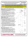
INSTALLATION OF STEM KIT ONTO CEILING
(Fig. 1 & 2)
(NOTE: If custom length is required see page 2.)
SAFETY STRAP
1. Assemble STEM to BALL ALIGNER using set screws. Pull wires
through BALL ALIGNER leaving no less than 6" exposed.
2. For sloped ceilings, position opening in CROSSBAR facing
upward. (Fig. 2) Install CROSSBAR using OUTLET BOX SCREWS.
3. Place BALL ALIGNER of STEM into CROSSBAR through side
access hole. When seated the BALL ALLIGNER keyway will line up
with TAB on CROSSBAR.
4. Slide SAFETY STRAP into position and secure in position with
screw.
5. Make Connections. Bare Copper and/or green insulation wire(s)
must be connected to SUPPLY GROUND. Connect WHITE
LEAD to NEUTRAL (WHITE) SUPPLY LEAD. Connect BLACK
LEAD to HOT SUPPLY LEAD. Use wire nuts (local hardware
items). Push spliced leads into outlet box.
CROSSBAR
BALL ALIGNER
OUTLET BOX
SCREWS
CANOPY
STEM
6. Slide CANOPY over CROSSBAR and push up against ceiling.
7. Insert SUPPORT COVER onto stem, secure with LOCK WASHER
and LOCK NUT.
SCREWS
CROSSBAR
SAFETY STRAP
SUPPORT
COVER
BALL ALIGNER
LOCK WASHER
LOCK NUT
FIG. 1
STEM
45° MAX.
FIG. 2
A
COMPANY
631 Airport Road, Fall River, MA 02720
READ AND UNDERSTAND THESE INSTRUCTIONS BEFORE INSTALLING FIXTURE
INSTRUCTION SHEET NO.
This fixture is intended for installation in accordance with the National Electrical Code and local regulations. To
assure full compliance with local codes and regulations, check with your local electrical inspector before
installation. To prevent electric shock, turn off electricity at fuse box before proceeding.
IS:CACS
Retain these instructions for maintenance reference.
Page 2 of 2
A0604
INSTALLATION PROCEDURE FOR: CEILING MOUNT STEM KIT CACS AND C4CS SERIES
USED WITH CEILING MOUNT CYLINDERS (ORDER SEPARATELY)
WARNING: USE ONLY FIXTURE PROVIDED BY LIGHTOLIER.
USE OF OTHER MANUFACTURES’ FIXTURES MAY VOID
THE UNDERWRITERS LABRATORIES LISTING AND COULD CONSTITUTE A FIRE HAZARD.
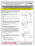
INSTALLATION OF CEILING MOUNT CYLINDER TO
STEM (Fig. 1 & 3)
FIBERGLASS
PAD (DISCARDED)
F IB ERGLA SS
P AD ( DIS CARDED)
1. Attach (2) SPRING CLIPS to CYLINDER HOUSING by sliding
SPRING CLIPS onto (2) raised pockets on top of CYLINDER
HOUSING. NOTE: Discard SPRING CLIPS for Cylinders which
do not have the raised pockets; these cylinders have integral tap
holes. (Fig. 3)
2. For C7CS series cylinders, tear off the fiberglass pad from top
of cylinder. The remaining fiberglass pad can be left inside of
SUPPORT COVER or removed. (Fig. 4)
3. Make Connections. Bare Copper and/or green insulation wire(s)
must be connected to SUPPLY GROUND. Connect WHITE
BALLAST LEAD to NUETRAL (WHITE) SUPPLY LEAD. Connect
BLACK BALLAST LEAD to HOT SUPPLY LEAD. Use wire nuts
(provided). Place spliced leads into SUPPORT COVER.
4. Align (2) holes in SUPPORT COVER with (2) SPRING CLIPS or
Tap holes, then tighten with (2) SCREWS (provided). (Fig. 1 & 3)
SUPPORT
COVER
FIG. 4
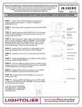
INSTRUCTIONS FOR SHORTENING STEM
ATTENTION: Cut end with smaller diameter holes only. (Fig.1)
CAUTION: Eye protection should always be worn when using hand
and power tools during the cutting procedure outlined below.
HAMMER
1. Using pipe cutting tool, shorten STEM to appropriate length. Clean
all burrs and sharp edges from cut end of Stem.
2. Position DRILL LOCATOR over cut end of STEM (Fig. 5). Gently
tap down on DRILL LOCATOR until fully seated on end of STEM.
3. Position CENTER PUNCH into bottom SLOT in DRILL LOCATOR
and mark a small dimple in STEM (Fig. 6).
4. Align 1/8" DRILL BIT (local hardware item) into bottom slot of
DRILL LOCATOR so tip of DRILL BIT rests in dimple (Fig. 7).
5. Drill hole completely through STEM allowing DRILL LOCATOR
to guide DRILL BIT. Do not force DRILL BIT. ItCENTER
is recommended to
hold DRILL LOCATOR securely in a
PUNCH
vise or other device prior to drilling hole.
DRILL LOCATOR
STEM (CUT)
FIG. 5
SLOT
SPRING
CLIPS
SLOT
DRILL BIT
FIG.6
FIG. 7
FIG. 3
A
COMPANY
631 Airport Road, Fall River, MA 02720