1
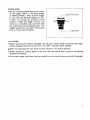
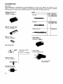
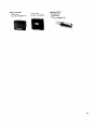
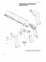
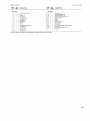
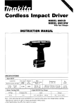
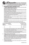
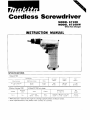
Cordless Screwdriver
MODEL 6710D
MODEL 6710DW
With Fast Charger
INSTRUCTION MANUAL
I
SPECIFICATIONS
Model 6 7 1 0 0
Wood screws
5 1 mm x 50 mm
11.4'
Machine screws
Nuts
6 mm
6 mm
(1/4")
f 114")
x 2 ' l
Battery Cartridge 7 0 0 0
speed
length
weight
220
195 mm
17-518")
1 1 kg
12.4 lhsl
Rimin
Model OC7100 Fast charger
Dimensions
iL x W x H)
7 2 V
1 Hr
A.C only
50 Hr
60 H r
DC
7 2 V
1 4 5 mm x 8 0 mm x 61 mm
( 5 314" x 3 1/8" x 2 318")
1
Net
weight
0 7 kg
I1 5 lhsl
IMPORTANT
SAFETY INSTRUCTIONS
(For All Tools)
WARNING: WHEN USING ELECTRIC TOOLS, BASIC SAFETY PRECAUTIONS SHOULD ALWAYS BE FOLLOWED TO
REDUCE THE RISK OF FIRE, ELECTRIC SHOCK, AND PERSONAL INJURY, INCLUDING THE FOLLOWING:
READ ALL INSTRUCTIONS.
1. KEEP WORK AREA CLEAN. Cluttered areas and benches invite injuries.
2. CONSIDER WORK AREA ENVIRONMENT. Don't use power tools in damp
3.
4.
5.
6.
7.
8.
9.
IO.
11.
12.
13.
2
or wet locations. Keep work area well lit. Don't expose power tools t o rain.
Don't use tool in presence of flammable liquids or gases.
KEEP CHILDREN AWAY. All visitors should be kept away from work area.
Don't let visitors contact tool or extension cord.
STORE IDLE TOOLS. When not in use, tools should be stored in dry, and
high or locked-up place - out of reach of children.
DON'T FORCE TOOL. It will do the job better and safer at the rate for which
it was intended.
USE RIGHT TOOL. Don't force small tool or attachment t o do the job of
a heavy-duty tool. Don't use tool for purpose not intended.
DRESS PROPERLY. Don't wear loose clothing or jewelry. They can be caught
in moving parts. Rubber gloves and non-skid footwear are recommended
when working outdoors. Wear protective hair covering t o contain long hair.
USE SAFETY GLASSES. Also use face or dust mask if cutting operation
is dusty.
DON'T ABUSE CORD. Never carry tool by cord or yank it t o disconnect from
receptacle. Keep cord from heat, oil, and sharp edges.
SECURE WORK. Use clamps or a vise t o hold work. It:s safer than using
your hand and it frees both hands t o operate tool.
DON'T OVERREACH. Keep proper footing and balance at all times.
MAINTAIN TOOLS WITH CARE. Keep tools sharp and clean for better and
safer performance. Follow instructions for lubricating and changing accessories. Inspect tool cords periodically and if damaged, have repaired by
authorized service facility. Inspect extension cords periodically and replace
if damaged. Keep handles dry, clean, and free from oil and grease.
DISCONNECT TOOLS. When not in use, before servicing, and when changing accessories, such as blades, bits, cutters.
14. REMOVE ADJUSTING KEYS AND WRENCHES. Form habit of checking t o
see that keys and adjusting wrenches are removed from tool before turning it on.
15. AVOID UNINTENTIONAL STARTING. Don't carry plugged-in tool with finger
on switch. Be sure switch is OFF when plugging in.
16. OUTDOOR USE EXTENSION CORDS. When tool is used outdoors, use only
extension cords intended for use outdoors and so marked.
17. STAY ALERT. Watch what you are doing, use common sense. Don't operate tool when you are tired.
18. CHECK DAMAGED PARTS. Before further use of the tool, a guard or other
part that is damaged should be carefully checked t o determine that it will
operate properly and perform its intended function. Check for alignment
of moving parts, binding of moving parts, breakage of parts, mounting, and
any other conditions that may affect its operation. A guard or other part
that is damaged should be properly repaired or replaced by an authorized
service center unless otherwise indicated elsewhere in this instruction manual. Have defective switches replaced by authorized service center. Don't
use tool if switch does not turn it on and off.
19. GUARD AGAINST ELECTRIC SHOCK. Prevent body contact with grounded
surfaces. For example; pipes, radiators, ranges, refrigerator enclosures.
20. REPLACEMENT PARTS. When servicing, use only identical replacement
parts.
VOLTAGE WARNING: Before connecting the tool t o a power source (receptacle,
outlet, etc.) be sure the voltage supplied is the same as that specified on the
nameplate of the tool. A power source with voltage greater than that specified
for the tool can result in SERIOUS INJURY t o the user - as well as damage t o
the tool. If in doubt, DO NOT PLUG IN THE TOOL. Using a power source with
voltage less than the nameplate rating is harmful t o the motor.
3
IMPORTANT SAFETY INSTRUCTIONS
I.
SAVE THESE INSTRUCTIONS
- This manual
contains important safety and operating instructions for battery charger.
2. Before using battery charger, read all instructions and cautionary markings
on (1) battery charger, (2)battery, and (3)product using battery.
3. CAUTION - To reduce risk of injury, charge only MAKITA Battery 7000.
Other types of .batteries may burst causing personal injury and damage.
4. Do not expose charger t o rain or snow.
5. Use of an attachment not recommended or sold by the battery charger
manufacturer may result in a risk of fire, electric shock, or injury t o persons.
6. To reduce risk of damage t o electric plug and cord, pull by plug rather than
cord when disconnecting charger.
7. Make sure cord is located so that it will not be stepped on, tripped over, or
otherwise subjected t o damage or stress.
8. A n extension cord should not be used unless absolutely necessary. Use of
improper extension cord could result in a risk of fire and electric shock. If
extension cord must be used, make sure:
a. That pins on plug of extension cord are the same number, size, and shape
as those of plug on charger;
b. That extension cord is properly wired and in good electrical condition; and
c. That wire size is at least as large as the one specified in the table below.
TABLE 1
RECOMMENDED MINIMUM AWG SIZE FOR
EXTENSION CORDS FOR BATTERY CHARGERS
Length of Cord (Feet)
AWG Size of Cord
4
25
18
50
18
100
18
150
16
ADDITIONAL SAFETY RULES
FOR CHARGER & BATTERY CARTRIDGE
1. Do not charge Battery Cartridge when temperature is BELOW 10°C
or ABOVE 4OoC (104OF).
(SOOF)
2. Do not attempt t o use a step-up transformer, an engine generator or DC power
receptacle.
3. Do not allow anything t o cover or clog the charger vents.
4. Always cover the battery terminals with the battery cover when the battery
cartridge is not used.
5. A battery short can cause a large current flow, overheating, possible burns
and even a breakdown.
(1) Do not touch the terminals with any conductive material.
(2) Avoid storing battery cartridge in a container with other metal objects such
as nails, coins, etc.
(3)Do not expose battery cartridge t o water or rain.
6. Do not store the tool and Battery Cartridge in locations where the temperature may reach or exceed 5OoC (122OF).
7. Do not incinerate the Battery Cartridge even if it is severely damaged or is
completely worn out. The battery cartridge can explode in a fire.
ADDITIONAL SAFETY RULES
FOR CORDLESS SCREWDRIVER AND DRILL
1. Be aware that this tool is always in an operating condition, because it does
not have t o be plugged into an electrical outlet.
2. Always be sure you have a firm footing.
Be sure no one is below when using the tool in high locations.
3.Hold the tool firmly.
4. Keep hands away from rotating parts.
5. When drilling into walls, floors or wherever "live" electrical wires may be encountered, DO NOT TOUCH ANY METAL PARTS OF THE TOOL!
Hold the tool only by the plastic handle or plastic tool body t o prevent electric
shock if you drill into a "live" wire.
6. Do not leave the tool running. Operate the tool only when hand-held.
7. Do not touch the drill bit or the workpiece immediately after operation, they
may be extremely hot and could burn your skin.
SAVE THESE INSTRUCTIONS.
5
Installing or removing battery cartridge
0 Always switch off the tool before insertion or removal of the battery cartridge.
To remove the battery cartridge, pull out
the set plate on the tool and grasp both
sides of the cartridge while withdrawing
it from the barrel.
.To insert the battery cartridge, align the
tongue on the battery cartridge with the
groove in the housing and slip it into
place. Snap the set plate back into place.
Be sure to close the set plate fully before
using the tool.
0
0
Do not use force when inserting the battery cartridge.
If the cartridge does not slide in easily, it i s not being inserted correctly.
Charging
Plug the fast charger into your power
source. Insert the battery cartridge so that
the plus and minus terminals on the battery cartridge are on the same sides as their
respective markings on the fast charger. Insert the cartridge fully into the port so that
it rests on the charger port floor.
The charging light will come on and charging will begin. If the charging light does not
come on, press the reset button. If the
charging light goes out within 10 seconds even after pressing the reset button a couple of
times, the battery cartridge is dead. (CAUTION : Wait for more than 5 seconds after the
charging light goes out to press the reset button again.) Replace it with a new one. When
the charging light goes out after about one hour, you may remove the fully charged
battery cartridge. After charging, unplug the charger from the power source.
CAUTION :
Your new battery cartridge is not charged. You will need to charge it before use.
0 If you try to charge a cartridge from a just-operatedtool, sometimes the charging light
will not come on. If this occurs, let the cartridge cool off for a while. Then re-insert
it and try to charge it once more.
0 When you charge a new battery cartridge or a battery cartridge which has not been used
for a long period, it may not accept a full charge. This i s a normal condition and does
not indicate a problem. You can recharge the battery cartridge fully after discharging
it almost completely a couple of times.
0 If you wish to charge two battery cartridges, allow 15 minutes between chargings on the
fast charger.
0
6
Switch action
0
Set the reversing switch lever just in front
of the trigger switch to Forward (FWD)
or Reverse (REV). Then pull the trigger
to turn the tool ON and release it to turn
it OFF. To change the direction of bit
rotation, release the trigger, let the tool
come to a complete stop, and then slide
the switch lever to the opposite side. The
trigger switch does not work if the switch
lever is in the neutral position.
I
R e v e r s i n g s w i t c h lever
I
I
Trigger
switch
CAUTIONS:
0 Before inserting the battery cartridge into the tool, always check to see that the trigger
switch actuates properly and returns to the "OFF" position when released.
When not operating the tool, keep the lever switch in the neutral position.
0
0
Before operation, always check to be sure that the switch lever is set for the desired
direction of rotation.
Pulling the trigger hard when the lever switch is set to neutral can cause switch breakage.
7
Fastening torque adjustment
The fastening torque may be adjusted by
turning the adjustment ring to align the
notched line on the ring with a number
on the indicator label. However, the
clearance between the ring and the cap
is 2.5 mm (1/8") maximum after one full
turn, and the ring should not be forced
beyond this point.
I
Fastening torque
adjustment ring
0
0
-
Bit
Turning the adjustment ring in the arrow
direction obtains a higher torque (HI
side); turning in the opposite direction
gives a lower torque (LOW side).
.Aligning the notched line with the number 4 on the indicator label provides the right
torque for setting a 4 mm (1/8") screw. Aligning to the 5 and 6 is suitable to drive a
5 mm (3/16") and 6 mm (1/4") screw, respectively.
0
If the adjust ring will not turn easily, switch the tool on and wait for the clutch to cut
in before making the torque adjustment.
.To back out (remove)an already driven screw, use a little more torque than you used to
drive the screw initially.
.Switch off as soon as the clutch cuts in. Continuous unnecessary clutching will loosen
the adjust ring and make it impossible to obtain the desired torque.
Grip
.The grip shown on the right is recommended.
8
Hole
0The hole on the heel of the tool is a convenient way to carry it by a cord, hook
or other means.
Drill chuck (Accessory)
0 To install a drill chuck, remove the insert
bit by a strong jerk, then a drill chuck can
be replaced with the insert bit by a sharp
push of the hand.
install the drill bit, place it in the
chuck as far as it will go. Tighten the
chuck collar by hand. Place the chuck
key in each of three holes, and tighten
clockwise.
.To
0
To remove the drill bit, place the chuck key into the chuck hole and turn counterclockwise.
CAUTIONS:
Be sure that the battery cartridge has been removed from the tool.
0
Always set the Forward-Reverse switch lever to
or adjusting bits or accessories.
NEUTRAL
when installing, removing
9
Screwdriving
Match your bit to your screw.
Phillips bits
Select your screws on
and
thenominal
right. diameter with the chart
Item
I
Rominal Diameter ( m m )
)
Bit No.
Wood Screw
2.1 - 2.7 13/32''- 118")
3.1 - 4.8 (1/8" - 3/16')
No. 2
No.3
1
5.1
(3/16")
Slotted bits
Select a slotted bit to match the slot on the screw heads. If the bit is too small for the
screw slot, the bit and/or screw head may be damaged.
MAINTENANCE
CAUTION:
Always be sure that the tool is switched off and the battery cartridge is removed before
attempting to perform inspection or maintenance.
To maintain product SAFETY and RELlABl LITY, repairs, maintenance and adjustment
should be performed by Makita Authorized or Factory Service Centers, always using
Makita replacement parts.
11
ACC ESSOR IES
CAUTION:
These accessories or attachments are recommended for use w i t h y o u r Makita t o o l specified in this
manual. The use o f any other accessories o r attachments m i g h t present a risk of i n j u r y to persons.
The accessories or attachments should be used o n l y in t h e proper and intended manner.
-
0
Charger 12V for cer
M o d e l D C 7112
Part No. 113109-0
Bits
Size
Part No.
#3
784215-0A
Phillips
Slotted
0
Battery cartridge 7 0 0 0
Part No. 632002-4
0
Battery cover
Part No. 414938-7
0
Drill chuck S 1 0
I--
Square d r i l l bit
1
D r i l l chuck attachment set
(Part No. 191448-8)
784606-0A
0
Fast charger
Model DC7100
Part No. 113086-6
0
Tool holster
Part No. 823033-3D
*Chuck key S i 0
Part NO.763419-1
J
0
Keyless drill chuck
Part No. 192077-0
12
Has storage space
f o r extra bits.
Carrying case
Steel case
,
part N ~823087-3
0
Plastic case
Part No. 181428-2
Battery holster
Holster holds
extra battery.
Part No. 823033-3C
13
Aug -09-'84
US
CORDLESS SCREWDRIVER
Model 67100
Note: The switch and other part configurations
may differ from country to country.
14
Aug - 0 9 4 4
MODEL 67101D
E
’M $&,
DESCRIPTION
MACHINE
1
1
1
1
1
1
1
1
1
1
1
I
1
1
2
1
- -
&
DESCRIPTION
MACHINE
~
2
3
4
5
6
7
6
3
10
11
12
13
14
15
‘i\M
US
Torque Adlust Ring 20
Cap
0 Ring 16
Guide Plate
Lock Washer 14
F Washer 1 4
Leal sprang
Sled Ball 3 5
Spindle
P,n 4
Compression Spring 14
T Washer 1 0
Clutch Cam
Steel Ball 6 4
Spur Gear 86
16
17
18
19
20
21
22
23
24
25
1
1
I
1
1
1
1
2
1
F Washer 8
Ball Bearing 60BLLB
Retaining Ring S - 6
Housing Set 1WNh Item
Battery 7000
361
Switch
Motor
Plane Bearing 3
Gear 9 - 0 4
1
Name Plate
26
7
28
36
37
1
1
2
P H Screw M4x22 IWiIh Washer)
Set Plate
Housing Set IWith Item 131
Rivet 0 - 5
-
-
Note The switch and other part specifications may differ from country to country
15
MAKITA LIMITED ONE YEAR WARRANTY
Warranty Policy
Every Makita tool is thoroughly inspected and tested before leaving the factory. It is warranted to
be free of defects from workmanship and materials for the period of ONE YEAR from the date of
original purchase. Should any trouble develop during this one-year period, return the COMPLETE
tool, freight prepaid, to one of Makita’s Factory or Authorized Service Centers. If inspection shows
the trouble is caused by defective workmanship or material, Makita will repair (or at our option,
replace) without charge.
This Warranty does not apply where:
repairs have been made or attempted by others:
repairs are required because of normal wear and tear:
The tool has been abused, misused or improperly maintained;
alterations have been made to the tool.
I
I N NO EVENT SHALL MAKITA BE LIABLE FOR ANY INDIRtCT. INCIDFNTAL OK CONSEOUENTIAL DAMAGFS FROM THE SALE OR USE OF THE PRODUCT. THIS DISCLAIMER
APPLIES BOTH DURING AND AFTER THE TERM OF THIS WARRANTY
MAKITA DISCLAIMS LIABILITY FOR ANY IMPLIED WARRANTIES, INCLUDING IMPLIED
WARRANTIES OF “MERCHANTABILITY” AND “FITNESS FOR A SPECIFIC PURPOSE,”
AFTER THE ONE-YEAR TERM OF THIS WARRANTY.
This Warranty gives you specific legal rights, and you may also have other rights which vary from
state to state. Some states do not allow the exclusion or Limitation of incidental or consequential
damages, so the above limitation or exclusion may not apply to you. Same states do not allow
limitation on how long an implied warranty lasts, so the above limitation may not apply to you.
Makita Corporation
3-11-8, Sumiyoshi-cho,
Anjo, Aichi 446 Japan
883548D067
PRINTED IN JAPAN
1992 - 4 - N