1
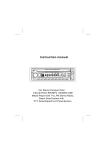
110 mm (4-318")
MODEL 1911B
INSTRUCTION MANUAL
DOUBLE
IIYSULATION
Planing w i d t h
Planing d e p t h
No loadspeed
Overall length
N e t weight
110 m m 14 3/8"1
2 mm (1116"l
16,000
3 5 5 m m 114")
4 2 k g ( 9 3 Ibs)
IRPMI
* Manufacturer reserves the right t o change specifications w i t h o u t notice
Note Specifications may d i f f e r f r o m country t o country
IMPORTANT
SAFETY INSTRUCTIONS
(For All Tools)
WARNING: WHEN USING ELECTRIC TOOLS, BASIC SAFETY PRECAUTIONS SHOULD ALWAYS BE FOLLOWED TO
REDUCE THE RISK OF FIRE, ELECTRIC SHOCK, AND PERSONAL INJURY, INCLUDING THE FOLLOWING:
READ ALL INSTRUCTIONS.
1. KEEP WORK AREA CLEAN. Cluttered areas and benches invite injuries.
2. CONSIDER WORK AREA ENVIRONMENT. Don't use power tools i n damp
or wet locations. Keep work area well lit. Don't expose power tools t o rain.
Don't use tool in presence of flammable liquids or gases.
3. KEEP CHILDREN AWAY. All visitors should be kept away from work area.
Don't let visitors contact tool or extension cord.
4. STORE IDLE TOOLS. When not in use, tools should be stored in dry, and high
or locked-up place - out of reach of children.
5. DON'T FORCE TOOL. It will do the job better and safer at the rate for which
it was intended.
6. USE RIGHT TOOL. Don't force smalf tool or attachment t o do the job of a
heavy-duty tool. Don't use tool for purpose not intended.
7 . DRESS PROPERLY. Don't wear loose clothing or jewelry. They can be caught
in moving parts. Rubber gloves and non-skid footwear are recommended
when working outdoors. Wear protective hair covering t o contain long hair.
8. USE SAFETY GLASSES. Also use face or dust mask if cutting operation is
dusty.
9. DON'T ABUSE CORD. Never carry tool by cord or yank it t o disconnect from
receptacle. Keep cord from heat, oil, and sharp edges.
IO. SECURE
WORK. Use clamps or a vise t o hold work. It's safer than using
your hand and it frees both hands t o operate tool.
11. DON'T OVERREACH. Keep proper footing and balance at all times.
12. MAINTAIN TOOLS WITH CARE. Keep tools sharp and clean for better and
safer performance. Follow instructions for lubricating and changing accessories. Inspect tool cords periodically and if damaged, have repaired by authorized service facility. Inspect extension cords periodically and replace if
damaged. Keep handles dry, clean, and free from oil and grease.
13. DISCONNECT TOOLS. When not in use, before servicing, and when changing accessories, such as blades, bits, cutters.
2
14. REMOVE ADJUSTING KEYS AND WRENCHES. Form habit of checking t o
see that keys and adjusting wrenches are removed f r o m tool before turning
it on.
15. AVOID UNINTENTIONAL STARTING. Don‘t carry plugged-in tool with finger
on switch. Be sure switch is OFF when plugging in.
16. OUTDOOR USE EXTENSION CORDS. When tool is used outdoors, use only
extension cords intended for use outdoors and so marked.
17. STAY ALERT. Watch what you are doing, use common sense. Don’t operate
tool when you are tired.
18. CHECK DAMAGED PARTS. Before further use of the tool, a guard or other
part that is damaged should be carefully checked t o determine that it will
operate properly and perform its intended function. Check for alignment of
moving parts, binding of moving parts, breakage of parts, mounting, and any
other conditions that may affect its operation. A guard or other part that
is damaged should be properly repaired or replaced by an authorized service center unless otherwise indicated elsewhere i n this instruction manual.
Have defective switches replaced by authorized service center. Don’t use
tool if switch does not turn it on and off.
19. GUARD AGAINST ELECTRIC SHOCK. Prevent body contact with grounded
surfaces. For example; pipes, radiators, ranges, refrigerator enclosures.
20. REPLACEMENT PARTS. When servicing, use only identical replacement parts.
VOLTAGE WARNIN?: Before connecting the tool t o a power source (receptacle,
outlet, etc.) be sure the voltage supplied is the same as that specified on the
nameplate of the tool. A power source w i t h voltage greater than that specified
for the tool can result in SERIOUS INJURY t o the user - as well as damage t o
the tool. If in doubt, DO NOT PLUG IN THE TOOL. Using a power source with
voltage less than the nameplate rating is harmful t o the motor.
3
ADDITIONAL SAFETY RULES
1. Rags, cloth, cord, string and the like should never be left around the work
area.
2. Avoid cutting nails. Inspect for and remove all nails f r o m the workpiece before operation.
3. Handle the blades very carefully.
4. Be sure the blade installation bolts are securely tightened before operation.
5. Hold the tool firmly with both hands.
6. Keep hands away from rotating parts.
7. Before using the tool on an actual workpiece, let it run for a while. Watch
for vibration or wobbling that could indicate poor installation or a poorly
balanced blade.
8. Make sure the blade is not contacting the workpiece before the switch is
turned on.
9. Wait until the blade attains full speed before cutting.
IO. Keep at least 200 m m ( 8 ” ) away from the tool at all times.
1 1 . Always switch o f f and wait for the blades t o come t o a complete stop before any adjusting.
12. Never stick your finger into the chip chute. Chute may jam when cutting
damp wood. Clean out chips w i t h a stick.
13. Do not leave the tool running. Operate the tool only when hand-held.
14.When leaving the planer, s w i t c h off and set it w i t h the front base up on a
wooden block, so that the blades do not contact anything.
15. Always change b o t h blades or covers o n the drum, otherwise the resulting
imbalance will cause vibration and shorten tool life.
SAVE THESE INSTRUCTIONS.
4
Removing or installing planer blades
CAUTION :
Always be sure that the tool is switched off and unplugged before removing or installing
the blade.
The blade i s secured with four bolts. Remove the inner two bolts entirely with
the socket wrench and loosen the outer
two bolts two turns each.
Fig. 1
Press down on the pin in the middle of the
drum with one end of the socket wrench
handle. The blade can be pushed and
jiggled out so as to be removed. (If the
blade becomes so short that it cannot be
grasped, you must remove the four bolts
and the drum cover. Then push the blade
out with one end of the socket wrench
handle.)
Fig. 2
To install the blades, first clean out all
chips or foreign matter adhering to the
drum or blades. Use blades of the same
dimensions and weight, or drum oscillationhibration will result, causing poor
planing action and, eventually, tool breakdown.
Insert the blade, holding both ends, so that
it protrudes from between the blade holder
and the drum. Then secure the four bolts
only finger-tight.
Fig. 3
5
Align the blade edge with the mark and
make the drum stationary by means of the
stopper pin. Place the leveller over the rear
base and blade, and press the leveller down
slightly. Release the stopper pin.
Stopper pin
When released
When secured
~
Fig.
Turn the drum in the direction of the
arrow (Fig. 6) to check the blade protrusion, holding the leveller flush against the
blade and rear base. The blade edge should
just contact the underside of the leveller.
When the blade edge does not protrude far
enough from the base, press down on the
pin in the middle of the drum with the
socket wrench handle, and adjust the
blades again as mentioned above. After
adjusting both blades, tighten the four installation bolts evenly and alternately with
the socket wrench.
4
-
I
Leveller
R
se
I
Fig.
CATU ION :
Tighten the blade installation bolts carefully when attaching the blades to the tool. A
loose installation bolt can be dangerous. Always check to see they are tightened securely.
6
For the correct planer blade setting
Your planing surface will end up rough and uneven, unless the blade is set properly and
securely. The blade must be mounted so that the cutting edge is absolutely level, that is,
parallel to the surface of the rear base. Below are some examples of proper and improper
settings.
(A) Front base (Movable shoe)
( B ) Rear base (Stationaryshoe)
Although this side view cannot show
it, t h e edges of t h e blades run perfectlv
parallel t o the rear base surface.
Cause: One or both blades f a i l s to have
edge parallel t o rear base line.
Nicks in
surface
a t start
to rear base line.
~~~&~~
Cause: One or
a t end
both blade edges pro-
trudes too far in relation t o rear
base line.
Adjusting depth of cut
Depth of cut may be adjusted by simply
turning the knob on the front of the tool.
Switch action
To start the tool, simply pull the trigger.
Release the trigger to stop. For continuous
operation, pull the trigger and then push in
the lock button. To stop the tool from the
locked position. pull the trigger fully, then
release it.
Fig. 8
CAUTION :
Before plugging in the tool, always check to see that the trigger switch actuates properly
and returns to the "OFF" position when released.
7
Planing operation
First, rest the tool front base flat upon the
workpiece surface without the blades making any contact. Switch on and wait until
the blades attain full speed. Then move the
tool gently forward. Apply pressure on the
front of tool a t the start of planing, and a t
the back a t the end of planing. Planing will
be easier if you incline the workpiece in
stationary fashion, so that you can plane
Fig. 9
somewhat downhill. The speed and depth
of cut determine the kind of finish. The power planer keeps cutting a t a speed that will
not result in jamming by chips. For rough cutting, the depth of cut can be increased, while
for a good finish you should reduce the depth of cut and advance the tool more slowly.
Chamfering
To make a cut as shown a t the right, align the "V" groove in the
front base with the edge of the workpiece and plane it as shown
in the figure (A).
A Ign the "V" groove w th
the edge of the worcpiece
Fig. 11
Sharpening planer baldes
Always keep your blades sharp for the best
performance possible. Use the sharpening
holder to remove nicks and produce a fine
edge.
I
1
Fig. 12
8
First, loosen the two wing nuts on the
holder and insert the blades ( A ) and (B)
so that they contact the sides (C) and (D).
Then tighten the wing nuts.
I
Wing nut
Side
(C)
Fig. 1
Immerse the dressing stone in water for 2
or 3 minutes before sharpening. Hold the
holder so that the blades both contact the
dressing stone for simultaneous sharpening
a t the same angle.
Fig. Id
MAINTENANCE
CAUTION :
Always be sure that the tool is switched off and unplugged before attempting to perform
inspection or maintenance.
The tool will stop when the carbon brushes wear to a certain length. When this occurs,
both carbon brushes should be replaced.
To maintain product SAFETY and RELIABILITY, repairs, carbon brush inspection and
replacement, any other maintenance or adjustment should be performed by Makita
Authorized or Factory Service Centers, always using Makita replacement parts.
9
ACC ESSOR I ES
CAUTION :
These accessories or attachments are recommended for use with your Makita tool specified in this
manual. The use of any other accessories or attachments might present a risk of injury t o persons.
The accessories or attachments should b e used only in the proper and intended manner.
0
Dressing stone
Part No. 794061 - 7
0
0
Cutter leveller
Part No. 155270.7
10
Guide rule
Part No. 164371-0
Sharpening holder assembly
Part No. 123055-9
Extension guide set
Part No. 191725-8
Socket wrench
Part No. 782209-3
0
Planer blade
(Material : Tungsten-carbide)
Width: 110 mm (4-3/8")
Part No. 793009-6
Planer blade
Width : 110 mm (4-3/8")
Part No. 793008-8
0
Screwdriver
Part No. 783002-8
Dec.-10-'87
EN
110 mm (4-3/8")
POWER PLANER
Model 1911B
Note: The switch. noise suppressor and other part configurations
may differ f r o m country t o country.
11
Mar - 3 1 - 8 9
ITEM
1
2 1
5
1
DESCRIPTION
1
1
1
1
10
11
12
13
14
15
16
17
18
19
21
22
23
24
25
26
27
28
29
30
31
32
A:D
1
4
2
2
1
2
1
1
1
1
1
1
1
6
1
1
1
1
1
1
2
1
US
'
',
Cord
Cord Guard
Strain Relief
Pan Head Screw M4x18 IWith Washerl
Switch
Handle Cover
Pan Head Screw M4x40 IWilh Washer1
Pan Head Screw M4x30 (With Washerl
Name Plate
Rivet 0 - 5
Brush Holder
Carbon Brush
Pan Head Screw M4x40 IWith Washerl
Pan Head Screw M4x14 IWifh Waaherl
Rear Cover
Knob 50
Fiat Washer 10
Main Frame
ComDresslon Spring 18
Rubber Packing
Front Base
Pan Head Screw M5x2O l W i ~ h
Washerl
Rear Base
Baffle Plate
Rubber Pin 4
Ball Bearing 60BLLB
Rubber Pm 4
FIELD ASSEMBLY
Hex holt M5x65 IWith Washer)
Inulation Washer
M
B
33
1
34
35
36
37
38
39
40
41
42
43
44
45
46
47
40
49
50
51
52
53
54
1
1
1
1
6
1
1
1
1
1
1
1
1
1
1
1
1
2
4
2
8
55
56
57
58
59
EO
61
1
1
1
1
1
1
1
ARMATURE ASSEMBLY
IWith Items 28 & 32 - 361
Fan 68
Dust Seal 10
Ball Bearing 6200LLB
Bracket
Pan Head Screw M4x30 (With Washer1
V Pulley 4-24L
Poly V B e l f 4 - 2 7 2
Belt Cover
Pan Head Screw M4x16 (With Washerl
V Pulley 4 - 3 8
Ball Bearing 600022
Washer 10
Drum
Washer 12
Ball Bearing 620122
Rubber Psn 6
Rubber Pin 4
Blade Holder
Pan Head Screw M 4 r 8 IWith Washerl
Drum Plate
Hex Flange Head Bolt M6x1 7
Leaf Spring
Pln
StOD Ring E - 3
Slopper P,"
COmDreSSlOn SDrlnQ 5
Pan 2
Nut M4-12
Note The switch and other part specifications may differ from country to country
MAKITA LIMrlED ONE YEAR WARRANTY
Warranty Policy
tvery Makita tool IS thoroughly inspected and tested before leaving the factory. It is warranted to
be free of defects from workmanship and materials for the period of ONE YEAR from the date of
original purchase. Should any trouble develop during this one-year period, return the COMPLETE
tool, freight prepaid, to one of Makita's Factory or Authorized Service Centers. If inspection shows
the trouble is caused by defective workmanship or material. Makita will repair (or at our optlan,
replace) without charge.
This Warranty does not apply where:
repairs have been made oratlemDted by others:
repairs are required because ofnormal wear and tear:
The tool has been abused, misused or impronerlv maintained:
alterations have been made to the 1001.
IN NO EVENT SHALL MAKITA BE LIABLE FOR ANY INDIRECT, INCIDENTAL OR CONSEQUENTIAL DAMAGES FROM THE SALE OR USE O F THE PRODUCT. THIS DISCLAIMER
APPLIES BOTH DURING AND AFTER THE TERM O F THIS WARRANTY.
MAKITA DISCLAIMS LIABILITY FOR ANY IMPLIED WARRANTIES, INCLUDING IMPLIED
WARRANTIES O F "MERCHANTABILITY" AND "FITNESS FOR A SPECIFIC PURPOSE,"
AFTER THE ONE-YEAR TERM O F THIS WARRANTY.
This Warranty gives you specific legal rights, and you may also have other nghts which vary from
state to state. Some States do not allow the exclusion or limitation of Incidental or consequential
damages, so the above limitation or exclusion may not apply to you. Some states do not allow
limitation on how long an imphed warranty lasts, so the above limitation may not apply to you.
Flrrtkir-,ud.
11-8,3-chome, Sumiyorhi-cho, Anjo, Aichi 446, Japan
883098 - 062
PRINTED IN JAPAN
1989 - 5 N
-