1
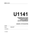
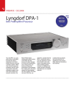
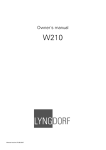
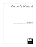
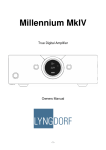
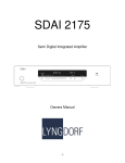
SDA 2175
Compact Analog Power Amplifier
Owner’s Manual
Table of Contents
WARNINGS ..............................................................................................................................................3
Explanation of symbols .........................................................................................................................3
Exclamation symbol .........................................................................................................................3
Lightning symbol..............................................................................................................................3
Important safety instructions .................................................................................................................4
Unpacking the SDA 2175 ..........................................................................................................................4
Accessories............................................................................................................................................5
Operating voltage ..................................................................................................................................5
Product Registrations .................................................................................................................................5
Introduction................................................................................................................................................6
Front panel .................................................................................................................................................6
Controls .................................................................................................................................................6
Indicators ...............................................................................................................................................6
Rear panel ..................................................................................................................................................7
Mains Connector ...................................................................................................................................7
Loudspeaker connectors ........................................................................................................................7
Input connectors ....................................................................................................................................8
Balanced inputs.................................................................................................................................8
Unbalanced inputs ............................................................................................................................9
Trigger connectors.................................................................................................................................9
Cleaning and maintenance .........................................................................................................................9
Always unplug the unit from the electrical outlet before cleaning. ......................................................9
Technical specifications...........................................................................................................................10
Audio ...................................................................................................................................................10
Protection ............................................................................................................................................11
Mains ...................................................................................................................................................11
Trigger .................................................................................................................................................11
Mechanical ..........................................................................................................................................11
Technical assistance.................................................................................................................................12
Support .....................................................................................................................................................12
2
WARNINGS
TO REDUCE THE RISK OF FIRE OR ELECTRICAL SHOCK, DO NOT EXPOSE THIS
APPLIANCE TO RAIN OR MOISTURE
CAUTION: TO REDUCE THE RISK OF ELECTRICAL SHOCK,
DO NOT REMOVE COVER. NO USER-SERVICEABLE PARTS
INSIDE. REFER SERVICING TO QUALIFIED PERSONNEL
.
CAUTION
RISK OF ELECTRICAL
SHOCK. DO NOT OPEN
Explanation of symbols
Exclamation symbol
The exclamation point within an equilateral triangle is intended to alert the
user to the presence of important operating and maintenance (service)
instructions in the literature accompanying the product.
Lightning symbol
The lightning with arrowhead symbol within an equilateral triangle is intended
to alert the user to the presence of uninsulated “Dangerous Voltage” within
the products’ enclosure that may be of sufficient magnitude to constitute a
risk of electrical shock to a person.
3
Important safety instructions
1:Read these instructions carefully before installing or operating this apparatus.
2:Keep these instructions.
3:Heed all warnings.
4:Follow all instructions.
5:Do not use this apparatus near water.
6:Clean only with a dry cloth.
7:Do not block any ventilation openings. Install in accordance with the manufacturer’s
instructions.
8:Do not install near any heat sources such as radiators, heat registers, stoves, or other
apparatus that produce heat.
9:Do not defeat the safety purpose of the grounding-type plug. A grounding-type plug has
two pins and a third grounding prong. The third prong is provided for your safety. If the
provided plug does not fit your outlet, consult an electrician for replacement of the
obsolete outlet.
10:Protect the power cord from being walked on or pinched, particularly at plugs,
convenience receptacles, and the point where they exit from the apparatus. Do not use
this unit with a damaged cord or plug.
11:Only use attachments and accessories specified by the manufacturer.
12:Use only with cart, stand, tripod, bracket, or table specified by the manufacturer, or sold
with the apparatus. When a cart is used, use caution when moving the cart/apparatus
combination to avoid injury from tip-over.
13:Unplug this apparatus during lightning storms or when unused for long periods of time.
14:Connect only to the proper mains voltage.
15:Do not connect any output from the amplifier to any other amplifier's output or any other
voltage source.
15:To avoid electrical shock, make sure that no conductive part of the loudspeaker wiring is
exposed while the amplifier is operating. Do not connect loudspeakers with uninsulated
terminals to the amplifier.
17:Refer all service to qualified service personnel. Service is required when the apparatus
has been damaged in any way, such as when the power supply cord or plug are
damaged, liquid has been spilled or objects have fallen into the apparatus, the apparatus
has been exposed to rain or moisture, does not operate normally or has been dropped.
Unpacking the SDA 2175
Carefully remove the unit and accessory kit from the carton, visually check for shipping
damage. Contact both the shipper and Lyngdorf Audio immediately if the unit shows any sign
of damage from mishandling. All Lyngdorf Audio equipment is carefully inspected before
leaving our factory.
KEEP SHIPPING CARTON AND PACKING MATERIALS for future use or in
the unlikely event that the unit needs service. If this unit is shipped without the
original packing, damage could occur and void the warranty.
4
Accessories
The following items are included in the accessories kit:
1:One mains cord
2:This manual
3:Customer registration form
Operating voltage
The SDA 2175 is available in a version for 115V mains voltage and in a version for 230V
mains voltage.
Check the label on the SDA 2175 rear panel and verify that you have the version with the
proper voltage for your area.
The 115V version requires a mains voltage of 100V-120V at 50-60Hz with a current rating of
8A.
The 230V version requires a mains voltage of 200V-240V at 50-60Hz with a current rating of
4A.
The mains voltage setting for your SDA 2175 can be changed ONLY BY A QUALIFIED
TECHNICIAN.
WARNING: Connect the power input only to the AC source printed on
the label. The warranty will not cover any damage caused by
connecting to the wrong type of AC mains.
Product Registrations
Please record the serial number of your amplifier here for future reference. The serial number
is printed on the label on the SDA 2175 rear panel. You will need this serial number, should
you ever require service for your SDA 2175 power amplifier.
SDA 2175 serial number: _____________________
Please fill in the enclosed Customer registration form and submit it to
Lyngdorf Audio, so that we can register you as owner of the unit and keep
you informed of future upgrades of the product.
5
Introduction
Lyngdorf SDA 2175 is a compact, high-performance analog switch-mode amplifier utilizing
some of the circuit topologies originally developed for the Lyngdorf Millennium and M2150
amplifiers. Due to the switch-mode topology, with an efficiency of up to 85%, the SDA 2175
will provide its output power with minimal heat dissipation. A massive power supply with a
650VA toroidal transformer and more than 40000 microF capacitors ensures that the SDA
2175 can deliver the current to drive even the most demanding loudspeakers. The SDA 2175
has 2 gold-plated XLR connectors accepting balanced input signals and 2 gold-plated phono
connectors for unbalanced signals. The input signal is fed to the power amplifier circuit via an
AC-coupled true instrumentation type input amplifier. Except for the input amplifier, the SDA
2175 is fully DC coupled with no bypass capacitors or DC servos to degrade performance.
The protection circuitry in the SDA 2175 shuts down the unit in case of over-temperature, DC
voltage on the outputs and too high output current. The amplifier will resume normal operation
when the fault condition is no longer present. A trigger input and bypass on 3.5 mm minijack
connectors allow the SDA 2175´s standby mode to be controlled remotely.
Front panel
Fig 1: SDA 2175 front panel.
Controls
Mains switch
Turns the power to the unit on or off.
Indicators
OPERATE
Indicates the operational status of the SDA 2175.
Off
The SDA 2175 is in standby mode (controlled via the TRIGGER input).
Flashing
The SDA 2175 is in soft-start mode or the protection circuit is engaged.
On
The SDA 2175 is operating normally.
POWER
Illuminates when power is applied to the SDA 2175 and the mains switch is ON.
6
Rear panel
Fig 2: SDA 2175 rear panel.
Mains Connector
Mains voltage to the SDA 2175 is applied via an IEC320 type connector. The supplied cable
with safety ground should be used to connect the SDA 2175 to a mains outlet.
WARNING: Connect the power input only to the AC source printed on
the label. The warranty will not cover any damage caused by connecting
to the wrong type of AC mains.
Loudspeaker connectors
The SDA 2175 loudspeaker connectors accept banana plugs, spades or
bare wire ends up to 5 mm in diameter. Connect the wires from each
loudspeaker to each channel's + and – terminals. Do not make any other
connections to the output terminals. The loudspeaker cable is inserted
into the slot in the loudspeaker terminal and the terminal is tightened
firmly.
WARNING: Always disconnect the SDA 2175 from the mains before
changing any connections to its inputs or outputs.
When the SDA 2175 is operating, there is 35V DC on its output terminals
with reference to ground.
7
Input connectors
The SDA 2175 has input sockets for both balanced and unbalanced signals, but only one may
be used at a time. The XLR and phono sockets are internally connected in parallel, so only
one set of the connectors should be connected externally. ALWAYS use EITHER the XLR
inputs OR the phono inputs. NEVER use both at the same time.
Fig 3: SDA 2175 Input configuration.
Balanced inputs
The balanced XLR inputs are wired in accordance with IEC268:
Pin 1: Chassis and ground.
Pin 2: Hot (+).
Pin 3: Cold (-).
Shell: Chassis and ground.
When the balanced inputs are used with a balanced source, the input selector switch MUST
be set to the BALANCED position. The switch position can be changed with a small
screwdriver.
If any cables are connected to the unbalanced inputs, remove these
before the switch is put in the BALANCED position.
We recommend the use of the balanced inputs whenever possible, as balanced signals are
much less sensitive to noise than unbalanced signals.
8
Unbalanced inputs
The unbalanced RCA inputs are wired in accordance with normal practice:
Shell: Chassis and ground.
Pin: Hot (+).
When the unbalanced inputs are used, the input selector switch MUST be set to the
UNBALANCED position. The switch position can be changed with a small screwdriver.
The switch must be changed to the unbalanced position before any
connections are made to the RCA connectors
Trigger connectors
The SDA 2175 is equipped with TRIGGER IN and TRIGGER BYPASS sockets. These are
ordinary 3.5 mm mono mini jack sockets.
When TRIGGER IN is left unconnected, the SDA 2175 will go into OPERATE mode when
power is applied.
If there is a plug in the TRIGGER IN socket, the SDA 2175 standby mode is controlled by the
voltage on the plug. With no voltage applied, the SDA 2175 will go into standby mode. If a DC
voltage of 5-24V or a 50Hz AC voltage of 4-17Vrms is applied, the SDA 2175 will go into
OPERATE mode.
TRIGGER BYPASS is for daisy-chaining a number of SDA 2175 and controlling them via the
same signal. Connect the control signal to TRIGGER IN on the first SDA 2175 and connect its
TRIGGER BYPASS to TRIGGER IN on the next unit, etc.
Cleaning and maintenance
Always unplug the unit from the electrical outlet
before cleaning.
This unit does not require any regular maintenance except to keep its exterior clean. Simply
wipe its exterior with a clean, soft cloth. A small amount of non-abrasive cleaner may be used
on the cloth to remove any excessive dirt or fingerprints. Do not use abrasive cleaners.
9
Technical specifications
Audio
Parameter
Balanced input connectors
Value
3-pin XLR, gold-plated
Balanced input impedance
Balanced input CMRR
Unbalanced input connectors
Unbalanced input impedance
Max. input voltage
Input sensitivity
Voltage gain
Output connectors
Note
Case=Gnd, Pin1=Gnd,
Pin2=Hot(+), Pin3=Cold(-)
AC-coupled
20 Hz – 20 kHz
Case=Gnd, Tip=Hot(+)
AC-coupled
10 KOhm
40 dB
Phono, gold-plated.
100 KOhm
±15Vp AC, 0-20 VDC
2V
200 W/8 Ohms
26 dB
4 insulated binding posts, gold- Will accept bare wire ends up
plated
to 5 mm diameter.
Output power, 8 Ohms
2 x 200 W
1 kHz, 1% THD+N
Output power, 4 Ohms
2 x 375 W
1 kHz, 1% THD+N
Nominal load impedance
4 - 8 Ohms
It is safe to operate the
amplifier with no load.
Frequency response
0.3 Hz – 33 kHz
-3 dB points, 8 Ohms load.
Frequency response
-0dB/+0.2dB
20 Hz - 20 kHz, 8 Ohms load
Frequency response
-0.2dB/+0dB
20 Hz – 20 kHz, 4 Ohms load
Output impedance
0.035 Ohms
20 Hz - 1 kHz
Output impedance
0.4 Ohms
20 kHz
THD+N, 1 W /8 Ohms
0.004%
A-wgt.
THD+N, 1 W/4 Ohms
0.006%
A-wgt.
THD+N, 100 W/8 Ohms
0.01%
A-wgt.
THD+N, 180 W/8 Ohms
0.07%
A-wgt.
THD+N, 275 W/4 Ohms
0.07%
A-wgt.
S/N ratio
117 dB
A-wgt. ref 200 W/8 Ohms.
Channel separation
84 dB
1 kHz, 200 W/8 Ohms.
Peak output current
±40 A
Output common mode voltage 35 VDC
Ref. Ground. The amplifier can
not be used in bridged mono
mode
Output DC voltage
±5 mV
All audio measurements, except frequency response, are measured with a 20KHz low-pass
filter in accordance with AES-17.
10
Protection
Parameter
Grounding
Output short circuit current
Output DC voltage
Over-temperature
Value
Note
Mains earth, chassis and audio
ground are connected
internally.
±40 A
±5 V @ <0.1 Hz
All heatsinks and mains
transformer
Mains
Parameter
Mains input connector
Mains voltage range
Mains voltage range
Internal mains fuse
Internal mains fuse
Power consumption
Power consumption
Power consumption
Power consumption
Value
IEC 320 cold type
100-120 VAC, 50–6 0Hz
200-240V AC, 50-60Hz
8 Amp
4 Amp
1.5 W
35 W
116 W
820 W
Note
Mains lead supplied
115 V version
230 V version
115 V version
230 V version
STANDBY mode
OPERATE mode, no output.
2 x 37.5 W/4 Ohms
2 x 300 W/4 Ohms.
Parameter
TRIGGER IN connector
TRIGGER BYPASS connector
TRIGGER IN impedance
TRIGGER IN sensitivity
Value
3.5 mm (1/8") mono jack
3.5 mm (1/8") mono jack
10 Kohm
4 VDC or 4Vp AC
Note
Case=Gnd, Tip=Input
Case=Gnd, Tip=Output
Max. input voltage
±25 Vp
Trigger
Positive DC voltage on Tip. AC
> 50 Hz
Mechanical
Parameter
Width
Depth
Value
450 mm (17.72")
340 mm (13.39")
Depth
361 mm (14.21")
Height
Height
Net weight
Shipping weight
88.8 mm (3.5")
100.6 mm (3.96")
15.5 kg (34 lb.)
17.5 kg (39 lb.)
11
Note
Excluding loudspeaker
connectors.
Including loudspeaker
connectors.
Excluding feet.
Including feet.
Technical assistance
If you have any problems with or questions regarding your Lyngdorf Audio product, please
contact Lyngdorf Audio or your nearest representative.
Support
Please check the Lyngdorf Audio Denmark website under “Support” for latest version of
control software, newest version of this document and “Questions and Answers”.
Lyngdorf Audio Denmark
Nordhavnsvej 12
DK7800 Skive
Denmark
Phone:
Phone:
Fax:
E-mail:
Web:
+45 46 91 10 90
+45 86 27 75 00
+45 86 27 45 00
[email protected]
http://www.lyngdorf.com
12