1
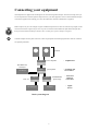
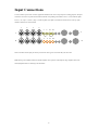
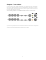
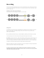
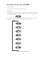
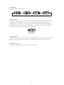
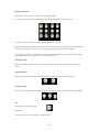
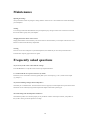
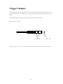
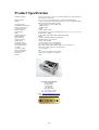
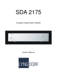
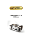
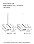
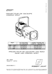
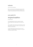
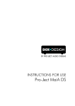
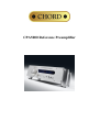
CPA5000 Reference Preamplifier
CONTENTS
PRODUCT DESCRIPTION
3
INVENTORY
3
WHEN SETTING UP
4
SAFETY WARNINGS
5
AC POWER CONNECTION
6
AC CONNECTOR
6
CONNECTING YOUR EQUIPMENT
7
INPUT CONNECTIONS
8
OUTPUT CONNECTIONS
9
RECORDING
10
AV BYPASS
11
HEADPHONES
11
EVERYDAY USE OF YOUR CPA5000
12
USING THE REMOTE CONTROL
15
MAINTENANCE
18
FREQUENTLY ASKED QUESTIONS
18
TRIGGER OUTPUTS
19
PRODUCT SPECIFICATION
20
2
CPA5000 Reference Preamplifier
Thank you for buying a Chord Electronics product.
Before you start to enjoy your preamplifier, please take a couple of minutes to read how to connect your audio equipment
and how to maximise your listening experience.
Product Description
The CPA5000 Reference Preamplifier uses our latest Ultra High Frequency power supply and ultra low noise circuitry
giving an amazing noise floor performance below -130dB. It also utilises solid milled aluminium shielding to prevent RF
interference.
Extra flexibility is now offered with four pairs of fully balanced XLR style inputs and an additional four pairs of RCA
style unbalanced inputs with two completely independent tape/recording loops. Selection can be made manually via the
front panel or using the supplied remote control.
Each input has six levels of gain that can be individually selected to prevent large changes in volume when switching
between inputs. All settings are stored via the microprocessor even if power is removed.
Inventory
As well as your CPA5000 and this user manual, you should also have received the following items.
1. System Remote Control including user manual
2. Power cord
3. Chord guarantee registration card
3
When setting up
To ensure that your CPA5000 works efficiently and safely, please pay particular attention to the following issues.
ventilation
Your CPA5000 should have at least 5cm of clear space all around it to ensure a free flow of air at all times. We do not
recommend that you place CPA5000 directly on a carpet. If you have the optional integra leg system fitted it is
recommended that the power amplifiers sit above the CPA5000.
AC lead and plug
All Chord equipment comes supplied with the correct power lead and plug. This should be used at all times.
if you need to fit a plug for UK/Europe
Connect the blue wire to the neutral terminal
Connect the brown wire to the live terminal
Connect the yellow/green wire to the earth terminal
if you need to fit a plug for US/Canada
Connect the white wire to the neutral terminal
Connect the black wire to the live terminal
Connect the green to the earth terminal
earthing issues in Europe
In some European countries a hum may occur if your CPA5000 is connected to mains sockets that do not have an earth. If
this is the case please ensure that:
1. Your transport is connected via a multi-way mains block, which contains an earth point
at each socket outlet. This is to ensure that the chassis metalwork of each item is
connected together.
2. We recommend that an earthing method for your building be implemented.
3. Use the connecting points on your Chord unit and connect to an available earth point.
4
Safety Warnings
It is important that your CPA5000 is earthed at all times via its own mains lead. Failure to do this may be hazardous. The
power supply components within the CPA5000 are designed to operate at lethal voltages and energy levels. Circuit
designs that embody these components conform to applicable safety requirements. Precautions must be taken to prevent
accidental contact with power-line potentials. Do not connect grounded test equipment.
There are no user serviceable parts within the CPA5000 Reference Preamplifier. Unauthorised
tampering or dismantling of this product will invalidate the warranty and could cause injury.
5
AC Power connection
The AC power connector of CPA5000 is at the back of the unit. Plug the female end (socket) of the power cord into the
power connector of the preamplifier, and the male end(plug) of the power cord into AC wall socket or AC extension
socket. The CPA5000 features a universal voltage high frequency power supply and will operate automatically from 65V
to 260V AC, 50 or 60Hz.
For optimum operation it is recommended that the CPA5000 is connected directly to the wall socket via the power
cord provided.
EARTH
AC Connector
IEC 10A
AC Connector
Powering up
Press the front panel switch marked power until it latches. The display and internal illumination will light up. The display
will show the selected input.
Powering down
Press the front panel switch marked power and release. The CPA5000 utilises soft start circuitry so the power can
switched on and off as often as required. There is no need to leave the CPA5000 permanently switched on.
6
Connecting your equipment
Chord amplifiers are supplied with and designed to be connected using balanced inputs. The interconnecting cables you
use will depend on the available input and output sockets on your other equipment. We have installed unbalanced inputs
on all Chord equipment, thus enabling you to mix Chord Electronics and other manufacturer’s equipment.
Balanced inputs carry twice the strength of signal of unbalanced inputs and are able to be fed down long lengths of cable
with less deterioration of signal. They are also less prone to interference than unbalanced inputs. Balanced inputs have
2
1
3
three pins and use Neutric XLR style connectors. Pin 1 is earth, pin 2 is positive and pin 3 is negative.
Unbalanced inputs use RCA phono connectors, which are gold plated with teflon high performance dielectric insulators
for optimum performance.
speakers
outputs
power amplifier
- Amplfication
pre-amplifier
- Switching and
level control
inputs
Red Reference
CD Player
outputs
CD Player
inputs
DAC 64
outputs
outputs
inputs
inputs
CD Transport
SYMPHONIC
phono stage
Turntable
Basic system diagram
7
- Data and
analogue
conversion
- Signal
Source
Input Connections
You can connect up to 8 items of source equipment. Included in this are two tape loops for recording purposes. All input
connections are on the rear panel and are marked with the corresponding Line number. Lines 1 to 4 are balanced inputs,
Line 5, 6, T1 ( Tape 1 ) and T2 ( Tape 2 ) are RCA phono style inputs. Left channel connections are at the top, right
channel connections are at the bottom.
1
2
3
4
5
6
T1 T2
L
L
1
2
3
4
OUT
IN
5
6
T1 T2
R
R
It does not matter which input you choose just select the same type of connection that your source has.
Note: Moving coil turntables without an internal amplifier will require an external phono stage amplifier such as the
Chord Symphonic before connecting to the CPA5000.
8
Output Connections
You need to connect the outputs on the back of the CPA5000 to a power amplifier in order to drive your loudspeakers.
There is one pair of balanced XLR outputs or one pair of RCA phono outputs each of which will drive a 68 ohm load.
Choose either depending on the appropriate input connection on your power amplifier. Left channel connections are at
the top, right channel connections are at the bottom.
Note: For optimum performance it is recommended that the balanced outputs are used where possible.
O/P
L
L
O/P
R
R
If you wish to bi-amp then ask your interconnect manufacturer to provide you with a balanced or RCA cable splitter. This
will split the single output from the CPA5000 into two signals one for each amplifier.
9
Recording
You can record an input from another audio source or two sources at the same time. If you’ve been using a tape recorder
as an input source, it will already be connected to the T1 or T2 IN sockets. If you haven’t, first connect the tape’s output
to the T1 or T2 IN sockets.
connecting to a Tape recorder to tape an audio source
Use RCA connectors to the left and right pairs marked OUT T1 or T2, or both.
T1 T2
L
L
OUT
T1 T2
R
R
selecting the bus
Your amplifier has two input selection buses. The default bus is bus A and this is the one you would use to choose your
inputs in everyday operation. The advantage of having two buses is that it allows for two tape recorders to tape
(different inputs) simultaneously.
Bus A is permanently connected to the Tape 1 (T1) output and Bus B is permanently connected to Tape 2 (T2) output.
You can tape from any source to either of the tape recorder outputs and both outputs can be monitored.
For example: You can play a CD on Line 1 on Bus A and record this by connecting your tape recorder to the Tape 1 (T1)
output. At the same time you can play a radio on Line 2 and connect another tape recorder to the Tape 2 (T2) output to
record the radio. Simply switch between Bus A and Bus B to monitor either of the sources. If you are recording an input
on one Bus you can still listen to another input whilst recording simply by selecting the other bus.
Note: In these examples we have used a tape recorder but you can use any recording device with a phono input. Minidisc,
CD/DVD recorders and PC soundcards are all normally compatible.
If you wish to record from one tape recorder to another then you will need to swap the tape recorder outputs.
Connect the first tape recorder to T1 IN and T2 OUT then the second to T2 IN and T1 OUT. Play the tape on BUS
A Tape 1 then record on the other tape recorder.
10
AV Bypass
AV Bypass mode allows the output of an AV surround sound processor to be connected and then routed directly to the
output of the CPA5000. The volume control and signal processing are bypassed so that the signal from the AV processor
reaches the power amplifier exactly as if it were connected directly. This has the advantage of allowing the CPA5000 to
remain in an AV system to give the best possible stereo two channel playback whilst still being able to switch to AV
bypass mode to allow the processor to playback multichannel film content.
A/V
O/P
L
L
A/V
O/P
R
R
Connect the front left and right outputs from your AV processor to the inputs on the back of the CPA5000 marked A/V.
Connect to the power amplifier as normal via either the balanced or RCA output on the CPA5000. Press the SET button
or Bypass on the remote control to activate the bypass option.
Note: The volume control in the CPA5000 will be bypassed so please check before switching on your AV processor that
the volume is turned down. When switching back please check that the volume on the CPA5000 has not inadvertently
been turned up before playing any music.
Headphones
The CPA5000 features two ¾ inch headphone sockets on the front panel.
to turn on headphone mode
1. Insert the headphone jack(s).
2. Press the SET button several times until H-PHN is displayed.
Headphone mode automatically mutes your loudspeakers. Headphone mode also prevents any volume control from
automatically un-muting your loudspeakers.
to turn off headphone mode
1. Press the SET button several times until your chosen output is displayed or
2. Press Mute on your remote control or
3. Press OUT1 on the remote control.
11
Everyday use of your CPA5000
Turning on your CPA5000
Press the power button on the front of the CPA5000. Press again to switch off.
Select the input source
Press and hold button A on the front panel to select Bus A. Your CPA5000 should be set to Bus A for normal operation
and the display will read the last selected input with no dots underneath. The selected input will automatically be sent to
the tape recording T1 phono outputs:
To assign the main output with a particular input signal, press button A and release several times to cycle through the 7
line inputs until the one you wish to use is displayed. The options are shown in the diagram below:
Cycle of input selection options for Bus A
12
To select Bus B press and hold the B button on the front panel. The currently selected line input will be displayed with
dots underneath to indicate Bus B. The selected input will automatically be sent to the tape recording T2 phono outputs:
Press and release the B button to cycle through the inputs:
Cycle of input selection options for Bus B
13
Select the output
Press the SET button to select the output.
adjusting the volume
Use the volume knob to adjust the volume manually. A clockwise turn of the knob will increase the volume and an anticlockwise turn of the knob will decrease the volume. The volume range runs from 0 to 98 and is displayed on the
CPA5000 display as you change the volume. If the outputs are muted, a volume change will un-mute the outputs to
prevent large changes in volume from damaging your loudspeakers. The volume level is shown on the display as the
word VOL and a two digit level as shown in the example diagram below.
Volume display
changing the balance
Use the balance knob to shift the balance between the left and right loudspeaker. A clockwise turn of the knob will shift
the balance to the right speaker and an anti –clockwise turn of the knob will shift the balance to the left speaker.
Switching the VU meter
Press the front panel button marked VU to switch the VU display on and off.
14
Using the remote control
The CPA5000 is supplied with the system remote control that is a universal controller for all Chord products, televisions
and DVD players. Full instructions can be found in the System Remote Manual supplied but for the purposes of
controlling the CPA5000 the main functions are listed on the next few pages.
Press the HIFI key
to begin controlling the CPA5000.
15
Selecting the input source
Press the Line- or Line+ keys on the centre control to cycle through the inputs.
For convenience you can directly access the first 5 inputs using the buttons at the bottom of the remote control.
The main everyday Bus A inputs are on the left whilst the Bus B inputs are on the right.
Press the button marked BUS A to select Bus A so you can listen to the source connected to this bus. Press the button marked BUS
B to select Bus B so you can listen to the source connected to Bus B. Bus B inputs are shown with dots underneath.
( As an example you can listen to your CD player on Line1 Bus A whilst recording the radio on Line2 Bus B. Press BUS B then
Line2. Start recording. The press BUS A then Line1 to listen to the CD player. )
Adjusting the volume
Press the Vol+ button on the centre control to increase the volume, press the Vol- button on the centre control to decrease the
volume.
Adjusting the balance
Press the Bal+ button to move the balance towards the right. Press the Bal- button to move the balance to the left.
Changing the output
Press OP1 to select the main output. Press BYPASS (OP2) to select AV Bypass output. OP1+2 has no function on the CPA5000.
Mute
Press the mute key to mute the CPA5000.
To un-mute
Press the mute key again, or select an output, or change the volume.
16
Input Gain Control
You can adjust the input gain on any of the Line inputs so that you can align the volume levels of your different sources. There are
six steps, which are x0.50,, x1.00, x1.5, x2.00, x2.5 and x3.00. Most modern input devices such as CD players have an
unbalanced output voltage of 2.5V and a balanced output 5V which does not require any increased gain amplification. In fact, to
increase the gain on such an output level can lead to distortion of the signal. However, older audio equipment may have an output
voltage of less than 2V, in which case you may like to adjust the input gain.
Note: When using the Chord DAC64 please set the line gain to 0.5.
Increasing the input gain
1.
Select the Line and Bus with the source that requires increased gain ( e.g. Line2 Bus A).
2.
On the remote control press BUS A ( or BUS B if you are using this bus ). The display will show the currently selected
gain for this input.
3.
Press the Vol+ key on the remote control to increase the gain.
4.
Repeat steps 2 and 3 to continue increasing the gain.
Press Bus A
then Vol+
Press Bus A
then Vol+
Example increasing gain on Bus A
Decreasing the input gain
1.
Select the Line and Bus with the source that requires the gain to be reduced ( e.g. Line2 Bus A).
2.
On the remote control press BUS A ( or BUS B if you are using this bus ). The display will show the currently selected
gain for this input.
3.
Press the Vol- key on the remote control to decrease the gain.
4.
Repeat steps 2 and 3 to continuedecreasing the gain.
Press Bus A
then Vol-
Press Bus A
then Vol-
Example decreasing gain on Bus A
17
Maintenance
adjusting the settings
Always remember to make any changes to settings with the volume set low or an instant burst of sound could damage
your loudspeaker.
cleaning
To clean finger marks and other blemishes from your amplifier spray clear glass cleaner onto a soft lint free cloth and
then use the cloth to gently clean your amplifier.
changing the batteries in the remote control
Simply push the button on the bottom of your remote control to release the battery cover. Replace with four new AAA
batteries as shown inside the battery compartment.
servicing
There are no user serviceable parts in your Chord amplifier, and it should only be serviced by Chord Electronics
Limited or their expressly approved Service Agents.
Frequently asked questions
why aren’t any of the remote control buttons working?
Press the HIFI button to set up the remote control for pre-amplifier functions.
I’ve connected all the wires up but I can’t hear any sound?
Ensure that you’ve selected the correct bus (typically Bus A), the correct input (e.g. Line 1) and the correct output
(e.g. Output 1 ).
why is there humming coming from the loudspeakers?
Check that you’ve earthed the unit. The interconnects need to be properly screened and placed away from mains cables.
Interference can be reduced by using balanced inputs and outputs instead of RCA phono types.
the sound coming from the loudspeakers is distorted
Check that the speakers are connected properly. It may be that the volume is turned up too loud for your speakers or
that you have set the gain for the input device too high.
18
Trigger Outputs
The CPA5000 features three trigger outputs that can be used to remotely trigger other Chord equipment. The external
trigger should be connected via a standard 1/8th inch / 3.5mm (mono or stereo) jack plug to the socket fitted to the rear of
the unit.
The CPA5000 should be switched off, the trigger lead inserted, then the unit switched back on.
The connections are as follows:
0V / Ground
+5V to +12V
c.
The tip of the plug is the +5V to +12V dc connection, the centre and rear connection are the 0V or ground connection.
19
Product Specification
Unbalanced Inputs:
Balanced Inputs:
Outputs:
AV Bypass input:
Intermodulation Distortion:
Signal to Noise Ratio:
Average Noise Floor:
Frequency Range:
Nominal Gain:
THD:
Channel Separation:
Channel Balance:
Input impedance:
Output impedance:
Output Offset:
Max Input Voltage:
Max Output Voltage:
Volume Performance:
VU Meter:
DC Ouput triggers:
Power Consumption:
Operating Voltage:
Dimensions:
Weight:
Line 5, Line 6, Tape 1, Tape 2. 4 x pairs RCA Phono style, gold-plated with
Teflon dielectric insulation.
Line 1 to Line 4. 3-pin female pairs of female Neutrik XLR inputs.
1 x pair of 3-pin male Neutrik XLR output with 1 x pair of gold-plated RCA
Phono wired asymmetrically in parallel.
1 x pair female 3-pin Neutrik XLR input
-120dB all inputs
-120dB all inputs
-130dB
2.5Hz – 200kHz (-3dB)
All inputs subject to 6 levels of switchable gain (x0.5, x1, x1.5, x2, x2.5, x3)
0.002% 20Hz – 20KHz
20 Hz 100dB, 1kHz 95dB, 10kHz 90dB, 20kHz 85dB
0.01dB
Unbalanced 50kOhms, Balanced 100kOhms
100 Ohms short circuit protected
0mVDC both channels
17Vrms balanced, 8.5V rms unbalanced
17V rms balanced, 8.5V rms unbalanced
0dB 0.5dB, -20dB 0.2dB, -60dB 0.24dB (13 secs for full travel )
Accurate to 0.5dB, 30 steps to VU Specification
12V active high x 3
50W
85 – 270V AC (50-60Hz) auto switching
420mm (w) x 355mm (d) x 133mm (h)
18Kg
Chord Electronics limited
The Pumphouse
Farleigh Bridge
Farleigh Lane
East Farleigh
Kent ME16 9NB
Tel: +44 (0)1622 721444
Fax: +44 (0)1622 721555
Email: [email protected]
http://www.chordelectronics.co.uk
20