1
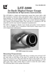
X-4
Fish-Finding Sonar
Installation and Operation
Instructions
Copyright © 2010 Navico
All rights reserved.
No part of this manual may be copied, reproduced, republished,
transmitted or distributed for any purpose, without prior written
consent of Navico. Any unauthorized commercial distribution of
this manual is strictly prohibited.
Lowrance® is a registered trademark of Navico.
Navico may find it necessary to change or end our policies, regulations,
and special offers at any time. We reserve the right to do so without
notice. All features and specifications subject to change without notice.
All screens in this manual are simulated.
For free owner's manuals and other information,
visit our web site:
www.lowrance.com
Table of Contents
Specifications: X-4 .............................................................................. iii
Preparations ......................................................................................... 1
Transducer Installation ....................................................................... 1
Selecting a Transducer Location ..................................................... 2
How low should you go? ................................................................... 4
Transom Transducer Assembly And Mounting ............................. 4
Trolling Motor Bracket Installation (single-frequency only) ...... 10
Transducer Orientation and Fish Arches ..................................... 11
Power Connections (permanent mount only) ................................... 13
Mounting the Sonar Unit: In-Dash, Bracket or Portable ............ 14
Bracket Installation ....................................................................... 15
Portable Sonar Installation ............................................................... 17
Installing the Batteries.................................................................. 18
Mounting the Unit ............................................................................. 19
Portable Transducer Assembly ..................................................... 20
Operation .......................................................................................... 22
Keyboard Basics ................................................................................. 22
Memory ............................................................................................... 22
Display ................................................................................................ 22
Full Chart ........................................................................................... 23
Depth Range ....................................................................................... 24
Zoom .................................................................................................... 24
Sensitivity ........................................................................................... 25
®
Grayline ............................................................................................ 26
Chart Speed ........................................................................................ 28
Fish I.D.™ ........................................................................................... 28
FishTrack™ ........................................................................................ 29
Fish Alarm .......................................................................................... 29
Depth Alarms ..................................................................................... 30
Shallow Alarm .................................................................................... 30
Deep Alarm ......................................................................................... 31
i
Battery Alarm .................................................................................... 32
Noise Reject and ASP™ ..................................................................... 33
Depth Display ..................................................................................... 33
Voltage ................................................................................................ 34
Temperature Display ......................................................................... 34
Units.................................................................................................... 34
Backlight ............................................................................................. 35
Contrast .............................................................................................. 35
Simulator ............................................................................................ 36
Set Language ...................................................................................... 36
Software Information ......................................................................... 36
Reset Options ..................................................................................... 36
ii
Specifications: X-4
General
Case size: ......................... 5.8" H x 4.3" W x 2.5" D (14.7 cm H x 10.8 cm
W x 6.6 cm D) sealed, waterproof; suitable for
saltwater use.
Display: ............................ High-contrast Film SuperTwist LCD. Diagonal viewing area: 3.5" (8.9 cm).
Resolution: ...................... 240 pixels (vert.) x 160 pixels (horiz.) resolution; 38,400 total pixels
Backlighting: .................. incandescent backlit screen
Input power: ................... 10 to 17 volts DC.
Current drain: ................ 170 ma lights off; 240 ma lights on.
Back-up memory: .......... Built-in memory stores sonar settings when
unit is turned off.
Sonar
Frequency: ...................... 200 kHz.
Transducers: ................... A Skimmer® transducer comes packed with
your unit. Its 20° cone angle offers a wide
fish detection area of up to 60º with high
sensitivity settings. Operates at boat speeds
up to 70 mph (61 kts).
Transmitter:.................... 800 watts peak-to-peak power (typical); 100
watts RMS power (typical).
Sonar sounding
depth capability:............ 600 feet (180 meters). Actual capability depends on transducer configuration and installation, bottom composition and water conditions. All sonar units typically read deeper in
fresh water than in salt water.
iii
Depth display: ................ Continuous digital readout.
Audible alarms: .............. Deep/shallow/fish.
Automatic ranging: ....... Yes, with instant screen updates.
Auto bottom track: ........ Yes.
Zoom bottom track:....... Yes.
Split-screen zoom: ......... No.
Surface water temp: ..... Yes, built into transducer. Optional external
temperature sensor or combo speed/temp
sensor available.
NOTICE!
The storage temperature for your unit is from -4 degrees to +167
degrees Fahrenheit (-20 degrees to +75 degrees Celsius). Extended
storage in temperatures higher or lower than specified will damage
the liquid crystal display in your unit. This type of damage is not
covered by the warranty. For more information, contact the factory's Customer Service Department; phone numbers are inside the
manual's back cover.
iv
Transducer Installation
Preparations
You can install the sonar in some other order if you prefer, but we recommend this installation sequence:
Caution:
You should read over this entire installation section before drilling any holes in your vehicle or vessel!
1. Determine the approximate location for the sonar/GPS unit, so you
can plan how and where to route the cables for the transducer and
power. This will help you make sure you have enough cable length for
the desired configuration.
2. Determine the approximate location for the transducer and its cable
route.
3. Determine the location of your battery or other power connection,
along with the power cable route.
4. Install the transducer and route the transducer cable to the sonar/GPS unit.
6. Install the power cable and route it to the sonar/GPS unit.
7. Mount the sonar/GPS unit to the bracket.
Transducer Installation
These instructions will help you install your Skimmer® transducer on a
transom, on a trolling motor or inside a hull. These instructions cover
both single- and dual-frequency Skimmer transducers. Please read all
instructions before proceeding with any installation.
The smaller single-frequency Skimmers typically use a one-piece, stainless steel mounting bracket. The larger dual-frequency Skimmers typically use a two-piece, plastic mounting bracket. The trolling motor
mount uses a one-piece plastic bracket with an adjustable strap.
1
These are all "kick-up" mounting brackets. They help prevent damage if the
transducer strikes an object while the boat is moving. If the transducer does
"kick-up," the bracket can easily be pushed back into place without tools.
Read these instructions carefully before attempting the installation.
Determine which of the mounting positions is right for your boat. Remember, the transducer installation is the most critical part of
a sonar installation.
NOTE:
The following installation types also call for these recommended
tools and required supplies that you must provide (supplies listed
here are not included):
Single-frequency transom installations
Tools include: two adjustable wrenches, drill, #29 (0.136") drill bit,
Phillips head screwdriver. Supplies: high quality, marine grade aboveor below-waterline sealant/adhesive compound.
Dual-frequency transom installations
Tools: two adjustable wrenches, drill, #20 (0.161") drill bit, Phillips head screwdriver. Supplies: four, 1" long, #12 stainless steel slotted wood screws, high
quality, marine grade above- or below-waterline sealant/adhesive compound.
Single-frequency trolling motor installations
Tools: two adjustable wrenches, Phillips head screwdriver. Supplies:
plastic cable ties.
Selecting a Transducer Location
1. The location must be in the water at all times, at all operating speeds.
2. The transducer must be placed in a location that has a smooth flow
of water at all times. If the transducer is not placed in a smooth flow of
water, interference caused by bubbles and turbulence will show on the
sonar's display in the form of random lines or dots whenever the boat is
moving.
2
NOTE:
Some aluminum boats with strakes or ribs on the outside of the
hull create large amounts of turbulence at high speed. These boats
typically have large outboard motors capable of propelling the boat
at speeds faster than 35 mph. Typically, a good transom location on
aluminum boats is between the ribs closest to the engine.
3. The transducer should be installed with its face pointing straight
down, if possible.
4. If the transducer is mounted on the transom, make sure it doesn't
interfere with the trailer or hauling of the boat. Also, don't mount it
closer than approximately one foot from the engine's lower unit. This
will prevent cavitation (bubble) interference with propeller operation.
5. If possible, route the transducer cable away from other wiring on the
boat. Electrical noise from engine wiring, bilge pumps and aerators can
be displayed on the sonar's screen. Use caution when routing the
transducer cable around these wires.
CAUTION: Clamp the transducer cable to transom near
the transducer. This will help
prevent the transducer from
entering the boat if it is
knocked off at high speed.
Good location
Poor location
Good
location
Good location
Poor angle
Good and poor transducer locations.
3
How low should you go?
For most situations, you should install your Skimmer transducer so
that its centerline is level with the bottom of the boat hull.
This will usually give you the best combination of smooth water flow
and protection from bangs and bumps.
Transom
Transducer
centerline
Hull bottom
Align transducer centerline with hull bottom.
However, there are times when you may need to adjust the transducer
slightly higher or lower. (The slots in the mounting brackets allow you
to loosen the screws and slide the transducer up or down.) If you frequently lose bottom signal lock while running at high speed, the transducer may be coming out of the water as you cross waves or wakes.
Move the transducer a little lower to help prevent this.
If you cruise or fish around lots of structure and cover, your transducer
may be frequently kicking up from object strikes. If you wish, you may
move the transducer a little higher for more protection.
There are two extremes you should avoid. Never let the edge of the
mounting bracket extend below the bottom of the hull. Never let the
bottom – the face – of the transducer rise above the bottom of the hull.
Transom Transducer Assembly And Mounting
The best way to install these transducers is to loosely assemble all of the
parts first, place the transducer's bracket against the transom and see if
you can move the transducer so that it's parallel with the ground.
4
The following instructions sometimes vary depending on the mounting
bracket that came with your transducer. Single-frequency Skimmers come
with a one-piece stainless steel bracket, while dual-frequency Skimmers
come with a two-piece plastic mounting bracket. Use the set of instructions that fits your model.
1. Assembling the bracket.
A. One-piece bracket: Press the two small plastic ratchets into the
sides of the metal bracket as shown in the following illustration. Notice
there are letters molded into each ratchet. Place each ratchet into the
bracket with the letter "A" aligned with the dot stamped into the metal
bracket. This position sets the transducer's coarse angle adjustment for a
14° transom. Most outboard and stern-drive transoms have a 14° angle.
Dot
Align plastic ratchets in bracket.
B. Two-piece bracket: Locate the four plastic ratchets in the transducer's hardware package. Press two ratchets into the sides of the plastic bracket and two on either side of the transducer as shown in the following illustrations. Notice there are letters molded into each ratchet.
Place the ratchets into the bracket with the letter "A" aligned with the
alignment mark molded into the bracket. Place the ratchets onto the
transducer with the letter "A" aligned with the 12 o'clock position on
the transducer stem. These positions set the transducer's coarse angle
adjustment for a 14° transom. Most outboard and stern-drive transoms
have a 14° angle.
5
Alignment letters
Alignment
positions
Transducer
Transducer bracket
Insert and align ratchets.
Transducer
Transducer bracket
Ratchet
Ratchet
Add ratchets to bracket and transducer.
2. Aligning the transducer on the transom.
To align the transducer to the transom, side the transducer between
the ratchets. Look at the transducer from the side and adjust it so that
its face is parallel to the ground. The alignment letters on either side of
the bracket need be the same.
6
If the transducer's face isn't parallel with the ground, remove the
transducer and ratchets from the bracket. Place the ratchets into the
holes in the bracket with the letter "B" aligned with the dot stamped in
the bracket.
Reassemble the transducer and bracket and place them against the
transom. Again, check to see if you can move the transducer so it's parallel with the ground. If you can, then go to step 3A.
3. Assembling the transducer.
A. One-piece bracket: Once you determine the correct position for
the ratchets, assemble the transducer as shown in the following figure. Don't tighten the lock nut at this time.
Position transducer mount on transom and mark mounting holes. Side
view shown, left, and seen from above at right.
7
washer
Nut
Rubber
washers
Metal washer
Bolt
Assemble transducer and bracket.
B. Two-piece bracket: Once you determine the correct position for
the ratchets, assemble the transducer as shown in the figure in step
2B. Don't tighten the lock nut at this time.
Lock washer
Bolt
Nut
Flat washer
Flat washer
Assemble transducer and bracket.
4. Drilling mounting holes.
Hold the transducer and bracket assembly against the transom. The
transducer should be roughly parallel to the ground. The transducer's centerline should be in line with the bottom of the hull. Don't let
the bracket extend below the hull!
8
Mark the center of each slot for the mounting screw pilot holes. You
will drill one hole in the center of each slot.
Drill the holes. For the one-piece bracket, use the #29 bit (for the #10
screws). For the two-piece bracket, use the #20 bit (for the #12 screws).
5. Attaching transducer to transom.
Both bracket types: Attach the transducer to the transom. Slide the
transducer up or down until it's aligned properly with the bottom of
the hull as shown in the preceding and following figures. Tighten the
bracket's mounting screws, sealing them with the sealant.
Adjust the transducer so that it's parallel to the ground even if you
have a Deep-"vee" hull. Tighten the nut until it touches the outer
washer, then add 1/4 turn. Don't over tighten the lock nut! If you do,
the transducer won't "kick-up" if it strikes an object in the water.
Bottom
of
hull
Flat-bottom hull
Deep-"vee" hull
Align transducer centerline with hull bottom and attach transducer to
transom. Rear view of dual-frequency Skimmer shown.
6. Route the transducer cable through or over the transom to the sonar
unit. Make sure to leave some slack in the cable at the transducer.
9
If possible, route the transducer cable away from other wiring on the
boat. Use caution when routing the transducer cable around these
wires.
WARNING:
Clamp the transducer cable to the transom close to the
transducer. This can prevent the transducer from entering the boat if it is knocked off at high speed.
Caution:
If you need to drill a hole in the transom to pass the connector
through, the required hole size be 1". If you drill the hole, make
sure it is located above the waterline. After installation, be sure
to seal the hole with the same marine grade above- or belowwaterline sealant used for the mounting screws.
7. Make a test run to determine the results. If the bottom is lost at
high speed, or if noise appears on the display, try sliding the transducer bracket down. This puts the transducer deeper into the water,
hopefully below the turbulence causing the noise. Don't allow the
transducer bracket to go below the bottom of the hull!
Trolling Motor Bracket Installation
(single-frequency only)
1. Attach the optional TMB-S bracket to the transducer as shown in the
following figure, using the hardware supplied with the transducer.
(Note: The internal tooth washer is supplied with the TMB-S.)
2. Slide the adjustable strap supplied with the TMB-S through the slot
in the transducer bracket and wrap it around the trolling motor. Position the transducer to aim straight down when the motor is in the
water. Tighten the strap securely.
10
Internal tooth washer
Bolt
Nut
Flat washer
Attach motor mounting bracket to transducer.
3. Route the transducer cable alongside the trolling motor shaft. Use
plastic ties (not included) to attach the transducer cable to the trolling motor shaft. Make sure there is enough slack in the cable for the
motor to turn freely. Route the cable to the sonar unit and the transducer is ready for use.
Transducer mounted on trolling motor, side view.
Transducer Orientation and Fish Arches
If you do not get good fish arches on your display, it could be because
the transducer is not parallel with the ground when the boat is at rest
in the water or at slow trolling speeds.
11
Partial fish arches
Transducer aimed
too far back
Transducer aimed
too far forward
Full fish arch
Proper transducer angle
Transducer angles and their effects on fish arches.
If the arch slopes up – but not back down – then the front of the transducer is too high and needs to be lowered. If only the back half of the
arch is printed, then the nose of the transducer is angled too far down
and needs to be raised.
NOTE:
Periodically wash the transducer's face with soap and water to remove
any oil film. Oil and dirt on the face will reduce the sensitivity or may
even prevent operation.
12
Power Connections (permanent mount only)
The unit works from a 12-volt battery system. You can attach the power cable to your boat's accessory or power buss (or directly to the battery). If you use an accessory buss but have problems with electrical
interference, attach the power cable directly to the battery. If the cable
is not long enough, splice #18 gauge wire onto it.
CAUTION:
When using the unit in a saltwater environment, we strongly recommend that you shut off the power supply to the power cable
when the unit is not in use. When the unit is turned off but still
connected to a power supply, electrolysis can occur in the power cable plug. This may result in corrosion of the plug body along with
the electrical contacts in the cable and the unit's power socket.
In saltwater environments we recommend you connect the power
cable to the auxiliary power switch included in most boat designs.
If that results in electrical interference, or if such a switch is not
available, we recommend connecting direct to the battery and installing an inline switch. This will let you shut off power to the
power cable when the unit is not in use. When you are not using
the unit, you should always shut off power to the power cable, especially when the power cable is disconnected from the unit.
If possible, keep the power cable away from other boat wiring, especially the engine's wires. This will provide the best isolation from electrical
noise. The power cable has two wires, red and black. Red is the positive
lead, black is negative or ground. Make sure to attach the in-line fuse
holder to the red lead as close to the power source as possible.
13
Red wire with
3 amp fuse
To unit
Black wire
12 volt
battery
Power connections for the X-4 sonar unit
(direct battery connection shown).
For example, if you have to extend the power cable to the battery or
power buss, attach one end of the fuse holder directly to the battery or
power buss. This will protect both the unit and the power cable in the
event of a short. It uses a 3-amp fuse.
Caution:
Do not use this product without a 3-amp fuse wired into the
power cable! Failure to use a 3-amp fuse will void your warranty.
This unit has reverse polarity protection. No damage will occur if the
power wires are reversed. However, the unit will not work until the
wires are attached correctly.
Mounting the Sonar Unit: In-Dash, Bracket or Portable
You can install the sonar unit on the top of a dash with the supplied
bracket. This unit can be installed in a dash with the optional FM-6 indash adapter kit. The FM-6 kit includes an instruction sheet, part 9880147-631, which contains a template for cutting out the mounting hole.
This document can be downloaded free from the www.lowrance.com
web site.
14
Bracket Installation
Recommended tools for this job include: drill, 1" (25.4 mm) drill bit and
a screwdriver. Required supplies for this job include: high quality, marine grade above- or below-waterline caulking compound, three #10
stainless steel screws. Screw length and type should be suitable for the
material on which you intend to mount the bracket.
Mount the unit in any convenient location, provided there is clearance
when it’s tilted for the best viewing angle. You should also make sure
there is enough room behind the unit to attach the power/transducer
cable. (See the following drawings, which show the dimensions of a
gimbal-mounted X-4 sonar unit.)
82.7
[3.26]
107.5
[4.23]
156
[6.26]
12.09 [0.48]
76.9
[3.03]
Millimeter
[Inch]
70.3
[2.77]
Front view (left) and side view (right) showing dimensions
of the X-4 when mounted on quick release bracket.
15
Holes in the bracket’s base allow wood screw or through-bolt mounting.
You may need to place a piece of plywood on the back side of thin panels to reinforce the panel and secure the mounting hardware.
Drill a 1" (25.4 mm) hole in the dash for the power/transducer and accessory cables. The best location for this hole is immediately under the
gimbal bracket location. This way, the bracket can be installed so that
it covers the hole, holds the cables in position and results in a neat installation. Some customers, however, prefer to mount the bracket to the
side of the cable hole — it's a matter of personal preference.
After drilling the hole, pass the connectors up through the hole from
under the dash. If you wish, you can fill in the hole around the cable with
a good marine caulking compound. (Some marine dealers stock cable hole
covers to conceal the opening.)
Using the Quick Release Mounting Bracket
These units use a quick release mounting bracket. When you run the
cables through the bracket's cable slots, make sure you allow enough
slack for tilting the unit and attaching the connector. (The snug fit of
the push-on waterproof connector requires some force to attach.)
16
Ratchet
Rear
view
Screw hole
Cable slot
Depress
ratchets
to release
Power/transducer
cable
X-4 quick release mounting bracket (left). Adjusting the viewing angle
of a display unit (right).
Attach the unit to the bracket by first connecting the power/transducer
and accessory cables. Then, hold the sonar unit vertically and slide it
onto the bracket from above. (The back of the unit should be touching
the front of the bracket as you lower it into position.) As you push
down, the unit will lock into place with a distinct click.
To adjust the viewing angle, pinch the ratchets with one hand, then tilt
the unit with your other hand. Release the ratchets and the unit locks
into the new position. To dismount the unit for storage, press the ratchets and lift the unit off the bracket.
Portable Sonar Installation
Like many Lowrance products, the X-4 sonar is capable of portable operation. It uses the optional PPP-12 portable power pack.
The PPP-12 package includes the power pack, battery adapter and a portable transducer. The transducer can be stored inside the power pack. The
PPP-12 requires eight AA alkaline batteries. Batteries are not included.
17
To use a portable power pack, you install the batteries and then attach
the sonar unit to the power pack's bracket. Plug in the power/transducer cable and you're ready to fish.
The PPP-12 has a quick-release mounting bracket built into the case.
Installing the Batteries
Open the case and lay it flat. (The latch is located below the handle.)
Insert eight "AA" size batteries into the battery adapter and place it in
the battery compartment. Slip the battery cover tabs into the slots in
the case wall, then close the battery cover with the thumb screw.
Plug the cable's power (dog bone-shaped) connector into the socket on
the battery compartment cover. Route the cable's unit connector and
about 6 inches (15.2 cm) of cable through the opening under the sonar
mount. Close the case bottom, using the slot in the case wall to avoid
pinching the cable. Turn the unit over to mount the sonar.
Route this
cable through
opening
Cable slot
in case wall
Install batteries in battery compartment (left).
Attach power cable, and route wires as shown (right).
CAUTION:
When using the sonar in a saltwater environment, we strongly
recommend that you unplug the power connector from the battery socket when the unit is not in use. When the unit is turned
off but still connected to a power supply, electrolysis can occur in
18
the power cable plug. This may result in corrosion of the plug
body along with the electrical contacts in the cable and the
unit's power socket.
Mounting the Unit
A quick-release mount is built into the top of the portable power pack. To
attach the unit, first plug in the cable connector. Then, hold the sonar unit
vertically and slide it onto the bracket from above. (The back of the unit
should be touching the front of the bracket as you lower it into position.)
As you push down, the unit will lock into place with a distinct click.
To adjust the viewing angle, pinch the quick-release mount's ratchets
with one hand, then tilt the unit with your other hand. Release the ratchets and the unit locks into the new position. To remove the unit from
the PPP-12, press the ratchets and lift the unit off the bracket.
Ratchet
To mount the sonar, slide the unit onto the bracket from above (left).
To adjust the view, press and release spring-loaded ratchets while tilting the unit (right).
19
Portable Transducer Assembly
Make sure there is one washer on each side of the transducer, inside the
bracket. Slide the other washer over the end of the bolt and screw on the nut.
Screw the suction cup onto the bracket
using the supplied screw and flat
washer. Tie the nylon cord through the
hole in the top of the bracket. When
Hull
using the transducer, tie the other end
of the nylon cord to the boat. This will
help prevent losing the transducer if it
comes off. Clean the chosen area of
the hull before attaching the suction cup. Locate the transducer on
the hull as shown in the following
figure. Don't let the bracket extend
Portable transducer installed on
below the hull, because water presboat transom.
sure against it can cause the suction
cup to come off at speed.
20
Tie
nylon
cord
here
Suction
cup
Bolt
Washer
Screw
Nut
Washer
Transducer
Portable transducer assembly: rear view (left) and side view (right).
NOTE:
For optimum operation, the portable transducer should be adjusted
so that it is parallel to the ground. For more information on this,
see the segment in the unit's operation manual on Transducer
Orientation and Fish Arches.
Moisten the suction cup and then press it onto the hull as firmly as
possible. Tie the nylon cord to the boat and set the power pack and sonar
unit in a location for easy viewing. Your portable sonar is now ready for use.
21
Operation
Keyboard Basics
The X-4 has five buttons including, Power/Clear, Menu Up, Menu
Down and two arrow keys.
PWR/CLEAR
Press the PWR key to turn the unit on and off. It also clears menus and
menu selections from the screen.1
3
2
MENU UP & MENU DOWN
The MENU UP key cycles forward through the menus. The MENU DOWN
key moves backward through the menus. To scroll through the unit's
menus, repeatedly press a MENU key.
UP & DOWN ARROWS (↑ ↓)
The UP and DOWN ARROW keys are used to adjust features and functions.
Memory
This unit has an internal backup battery that saves the following user
settings when power is turned off: Units of Measure, Temp Size, Depth
Size, Fish I.D. mode, Noise Reject mode, Range mode, Zoom, Sensitivity,
Grayline, Chart Speed, Battery Alarm, Display Contrast, Backlight,
Language, Fish Alarm, Battery Alarm and Shallow and Deep alarms.
Display
When the unit is turned, the backlight menu will appear. Use the
ARROW keys to turn the backlight on or off. Press PWR to clear the
menu from the screen.
Depth range will be displayed on the left side of the screen. In the following figure, the screen shows a depth range from 0 to 80 feet and the
bottom depth is 36.9 feet, shown by the digital sonar. The water temperature is 34.5° F.
22
Digital depth
Surface signal
Water Temp
Fish symbols
Bottom signal
Structure
or cover
Depth range
at bottom of
depth scale
Grayline®
Full Chart page. Fish I.D. (fish symbols) is on by default.
Full Chart
On the Full Chart page, the bottom signal scrolls across the screen
from right to left. The line at the top of the screen represents the surface. The bottom depth is shown in the upper left-hand corner.
If the transducer with a built-in temperature sensor is connected, the
water temperature also will be shown.
Digital depth
Surface clutter
Water Temp
Bait fish
Structure
or cover
Bottom signal
Fish arches
Depth range
at bottom of
depth scale
Grayline®
Full Chart page with Fish I.D. turned off.
23
Depth Range
Depth Range has two modes: Automatic and Manual. In auto range
mode, the unit always keeps the bottom displayed in the lower portion
of the screen. If you want to manually select a depth range, you can
override automatic depth range control.
Depth Range menu with Manual setting selected (left). Range Size
menu with 0-80 ft highlighted (center). Zoom Range menu with the 4080 foot zoom selected.
To turn off Auto Depth Range:
1. Repeatedly press MENU until the DEPTH RANGE menu appears. Press ↓,
select MANUAL and then press MENU UP to display the RANGE SIZE menu.
2. Use the arrow keys to select a desired depth range. Press PWR to
clear the menu from the display.
Zoom
The zoom feature enlarges all images on the screen by doubling the size
of the echoes (a 2X zoom).
To turn on the Zoom feature:
1. Press the MENU key until the ZOOM menu appears. Press ↑ to select
ON, then press PWR to clear the menu.
24
You can tell when the display is in Zoom mode because the top depth
scale on the left of the screen will no longer show zero. If the current
range is 0 to 80 feet, turning on the zoom feature will magnify the water
column between 40 feet to 80 feet.
To turn off the zoom feature:
1. Press the MENU key until the ZOOM menu appears. Press ↓ to select
OFF, then press PWR to clear the menu. The top of the depth range scale
returns to zero.
NOTE:
You can select from these zoom size ranges: 0-10, 5-15, 10-20, 1530, 20-40, 30-60, 40-80, 50-100, 75-150, 100-200, 150-300, 200-400,
300-600, 400-800, 500-1000, 750-1500 and 1000-2000.
To select a zoom range:
1. Make sure Depth Range is set to manual mode. Press MENU until
the ZOOM menu appears. Press ↑ to select ON, then press MENU UP to
display the ZOOM RANGE menu.
2. Use the arrow keys to select a desired zoom size. Press PWR to clear
the menu from the display.
Sensitivity
Sensitivity adjusts the way echoes will be displayed on the screen. If
you want to see more detail, try increase sensitivity. If your unit is
picking up a lot of clutter, decrease the sensitivity to reduce the
amount of clutter displayed on the screen.
25
Sensitivity set to manual mode (left). Sensitivity control bar (right).
To adjust sensitivity in Auto Mode:
1. Press MENU until the SENSITIVITY control bar appears. Press ↑ to increase
the sensitivity, ↓ to decrease it.
2. Press PWR to clear the menu. If you reach the maximum or minimum
sensitivity level, a tone will sound.
To turn on Manual mode:
1. Repeatedly press Menu to display the Sensitivity menu. Highlight
MANUAL and press PWR to clear the menu.
Grayline®
Grayline® helps you tell the difference between a hard and a soft bottom by coloring weaker sonar returns (soft, muddy or weedy bottom)
with a narrow gray line or no gray line at all. A strong sonar return
(hard bottom) will be displayed as a wide gray line.
26
Bait
school
Fish
arches
Sensitivity at 71 percent (left). Sensitivity at 100 percent (right).
To change the Grayline level:
1. Press MENU until the GRAYLINE control bar appears.
2. Press ↑ to increase the level of Grayline or press ↓ to decrease it. If
you reach the maximum or minimum level, a tone will sound. Press
PWR to clear the menu.
Wider
Grayline®
Thin or no Grayline®
A small amount of Grayline indicates a soft bottom (left), probably
sand or mud. More Grayline indicates a harder, rocky bottom (right).
27
Chart Speed
The rate that echoes scroll across the screen is called the chart scroll
speed. The default for this unit is the maximum, 100 percent.
Chart Speed control bar.
NOTE:
When you are stationary or traveling slowly and using a higher
chart speed, a fish swimming through the sonar signal will be displayed as a long line instead of a fish arch. You can counteract this
by decreasing the chart speed to match the speed of your boat,
which will shorten the line, making it look more like a fish arch.
To adjust Chart Speed:
1. Press MENU until the CHART SPEED control bar appears. Press ↑ to in-
crease the speed of the chart. Press ↓ to decrease it.
2. Press PWR to clear the menu.
Fish I.D.™
The Fish I.D. feature displays fish symbols on the screen in place of the
actual fish echoes. There are three symbol sizes: small, medium and
large. These show the relative size between targets.
28
To see what's under your boat in maximum detail, we recommend you
turn off Fish I.D. and begin learning to interpret fish arches.
To turn Fish I.D. on/off:
1. Press MENU until the FISH ID menu appears. Press ↓ to select ON/OFF.
2. Press PWR to clear the menu from the display.
Fish
arches
Fish I.D.
symbols
Underwater scene in normal fish arch mode (left). Fish I.D. menu with
the feature turned on (right).
FishTrack™
The FishTrack™ feature shows the depth of a fish symbol when it appears on the display.
To turn on/off FishTrack:
1. Press MENU until the FISH ID menu appears. Press ↑ ↓ to select TRACK
or OFF.
2. Press PWR. (If you want to turn off FishTrack depths but leave Fish
I.D. on, press ↓ to select ON, then press PWR.) Remember, Fish I.D.
must be on in order to use the FishTrack feature.
Fish Alarm
The Fish Alarm sounds a tone when a fish symbol appears on the
screen. The Fish I.D. feature must be turned on for fish alarms to work.
29
To turn on/off the fish alarm:
1. Press MENU until the FISH ALARM menu appears. Press ↑ to select
ON/OFF.
2. Press PWR to clear the menu from the screen
Fish ID menu and symbol with FishTrack on (left). Fish Alarm menu
(right).
Depth Alarms
The depth alarms consist of a shallow and a deep alarm. The shallow
alarm sounds an alarm tone when the bottom is shallower than the
alarm's setting. The deep alarm sounds a tone when the bottom is deeper than the alarm's setting.
Shallow Alarm
To set the shallow alarm:
1. Press MENU repeatedly until SHALLOW ALARM appears.
2. Press ↓ to SET VALUE. Use ↑ ↓ to enter the first number in the dialog
box, then press DOWN MENU to move to the next digit. Repeat those
steps until the desired depth has been entered in the dialog box. To
move the cursor back to any of the previously entered numbers, press
UP MENU.
30
3. Press PWR to return to the Shallow Alarm menu. Use ↑ to select ON,
which will turn on the alarm, then press PWR to clear the menu. When
the alarm goes off a message will appear and a tone will sound. Press
PWR to silence the alarm.
To turn off the alarm:
1. Repeatedly press MENU until the SHALLOW ALARM menu appears. Press
↓ to OFF.
2. Press PWR to clear the menu.
Shallow Alarm Value Dialog box (left). Shallow Alarm menu (right).
Deep Alarm
To set the deep alarm:
1. Press MENU repeatedly until DEEP ALARM appears.
2. Press ↓ to SET VALUE. The Deep Alarm Value dialog box will appear.
Use ↓ to enter the first number in the dialog box, then press DOWN
MENU to move to the next digit. Repeat those steps until the desired
depth has been entered in the dialog box. To move the cursor back to
any of the previously entered numbers, press UP MENU.
3. Press PWR to return to the Deep Alarm menu. Use ↑ to select ON.
Press PWR to clear the menu. When the bottom depth becomes deeper
than the alarm’s setting, an alarm will sound and a message will appear on the screen.
31
To turn off the alarm:
1. Repeatedly press MENU until the DEEP ALARM menu appears. Press ↓
to OFF. Press PWR to clear the menu.
Battery Alarm
To set the Battery alarm:
1. Press MENU repeatedly until BATTERY ALARM appears.
2. Press the ↓ to SET VALUE. The Low Battery Alarm Value dialog box
will appear. Input a voltage value between 7 and 18 volts. Use the ↑ ↓
keys to enter the first number in the dialog box, then press DOWN
MENU to move to the next digit. Repeat those steps until the desired
value has been entered in the dialog box. To move the cursor back to
any of the previously entered numbers, press UP MENU.
Low Battery Alarm Value (left). Battery Alarm menu (right).
3. Press PWR to return to the Battery Alarm menu. Use ↑ to select ON,
which will turn on the alarm, then press PWR to clear the menu. If the
voltage value falls below the alarm’s setting, the alarm will sound and
a message will appear on the screen.
To turn off the alarm:
1. Repeatedly press MENU until the BATTERY ALARM menu appears. Press
↓ to OFF.
2. Press PWR to clear the menu.
32
Noise Reject and ASP™
The ASP™ (Advanced Signal Processing) feature is a noise rejection
system that constantly evaluates the effects of boat speed, water conditions and electrical interference and automatically gives you the best
display possible under most conditions. The ASP feature has three settings — Off, Low and High.
To change the ASP setting:
1. Press MENU until the NOISE REJECTION menu appears. Use ↑ ↓ to select
the desired setting.
2. Press PWR to clear the menu.
Depth Display
Depth may be displayed in a small, medium or large size, or can be
turned off completely.
To display Depth:
1. Repeatedly press MENU until the DEPTH menu appears. Use ↑ ↓ to select the size of the depth display.
2. Press PWR to clear the menu.
Depth display set to large (left). Voltage display set to small (right).
33
Voltage
The Voltage menu allows you to display battery voltage in a small or
medium size, or can be turned off completely.
To display battery voltage:
1. Repeatedly press MENU until the VOLTAGE menu appears. Use ↑ ↓ to
select the size of the voltage display.
2. Press PWR to clear the menu.
Temperature Display
Temperature may be displayed in a small or medium size, or can be
turned off completely.
To display Temperature:
1. Repeatedly press MENU until the TEMPERATURE menu appears. Use ↑ ↓
to select the size of the temperature display.
2. Press PWR to clear the menu.
Units
This unit can show the depth in feet or meters and temperature in Celsius or Fahrenheit.
The Backlight menu with backlight turned on.
34
To change units of measure:
1. Press MENU until the UNITS menu appears. Use the arrow keys to se-
lect the desired unit of measure.
2. Press the PWR key to clear the menu.
Backlight
Turning on your unit's backlight will allow you to use it at night.
To turn the backlight on/off:
1. Press MENU repeatedly until the BACKLIGHT menu appears. Press ↑ to
turn the light on or ↓ to turn it off.
2. Press PWR to clear the menu.
Contrast
The unit’s display contrast is adjustable to suit different lighting conditions. It will help you see the screen from different angles or at various
times of the day.
To adjust the contrast:
1. Press MENU until the CONTRAST control bar appears. To decrease
screen contrast, press ↓. Press ↑ to increase screen contrast.
2. Press the PWR key to clear the menu.
Contrast control bar (center). Simulator menu (center). Languages
menu with English selected (right).
35
Simulator
This unit has a simulator that displays a simulated bottom signal with
fish signals.
To turn on/off the simulator:
1. Repeatedly press MENU until the SIMULATOR menu appears. Press ↑ ↓
to turn it on or off.
2. Press PWR to clear the menu.
Set Language
This unit's menus are available in 11 languages: English, French,
German, Spanish, Italian, Danish, Swedish, Russian, Czech, Dutch and
Finnish.
To select a language:
1. Repeatedly press MENU until the Languages menu appears.
2. Use ↑ ↓ to select the desired language. All menus now appear in the
language you selected. Press PWR to clear the menu.
Software Information
The Software Information screen shows what version of software your
unit is using.
To show the software information:
1. Press MENU until the SOFTWARE INFORMATION menu appears.
2. Press PWR to clear the screen.
Reset Options
This command is used to reset all features, options and settings to their
original factory defaults.
To Reset Options:
1. Turn the unit off. Press and hold ↓ and the MENU DOWN key at the
same time while pressing the PWR key.
2. Release the keys as the unit powers up. The unit will turn on with
factory settings restored.
36
Accessory Ordering Information
for all countries
To order Lowrance GPS accessories such as computer cables or MMC
cards, please contact:
1) Your local marine dealer or consumer electronics store. Most quality
dealers that handle marine electronic equipment or other consumer
electronics should be able to assist you with these items.
To locate a Lowrance dealer near you, visit our web site,
www.lowrance.com and look for the Dealer Locator. Or, you can consult
your telephone directory for listings.
2) U.S. customers: LEI Extras Inc., PO Box 129, Catoosa, OK 74015-0129
Call 1-800-324-0045 or visit our web site www.lei-extras.com.
3) Canadian customers can write:
Lowrance/Eagle Canada, 919 Matheson Blvd. E. Mississauga, Ontario
L4W2R7 or fax 905-629-3118.
Shipping Information
If it becomes necessary to send a product for repair or replacement, you
must first receive a return authorization number from Customer
Service. Products shipped without a return authorization will not be
accepted. When shipping, we recommend you do the following:
1. Always use the original shipping container and filler material the
product was packed in.
2. Always insure the parcel against damage or loss during shipment.
Lowrance does not assume responsibility for goods lost or damaged in
transit.
3. For proper testing, include a brief note with the product describing
the problem. Be sure to include your name, return shipping address
and a daytime telephone number.
Visit our web site:
www.lowrance.com
*988-10014-001*
© Copyright 2010
All Rights Reserved
Navico Holding AS.