1
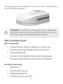
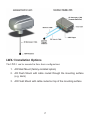
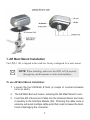
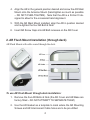
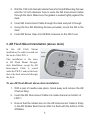
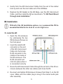
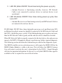
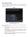
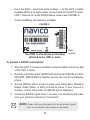
LWX-1
Satellite Weather Radio Module
Installation Instructions
988-0158-13A
Copyright © 2009 Navico
All rights reserved.
No part of this manual may be copied, reproduced, republished, transmitted or
distributed for any purpose, without prior written consent of Lowrance Electronics.
Lowrance® is a registered trademark of Navico.
Navico may find it necessary to change or end our policies, regulations and special
offers at any time. We reserve the right to do so without notice. All features and
specifications subject to change without notice.
For downloadable owner’s manuals and the most current information on this
product and its operation and accessories, visit our web site:
www.lowrance.com
Navico, Inc.
12000 E. Skelly Dr.
Tulsa, OK USA 74128-2486
This document covers the installation of the Lowrance LWX-1 and details how to
activate a SIRIUS subscription.
CAUTION: For the LWX-1 to work properly with your HDS product,
you will need code version 2.0 or greater. Visit www.lowrance.com for
instructions on how to download/install software updates.
!
LWX-1 package include:
Main Components:
1. Antenna Receiver (AR) pre-configured for a mast mount
•
AR Interconnect Cable (attached to AR) connects to IM
2. Interface Module (IM)
•
IM Power Cable (attached to IM) connects to Vessel power
•
IM Network Cable (attached to IM) connects to ChartPlotter
Mounting Components:
1. AR Gasket (1)
2. AR Mounting Screws (4)
3. IM Mounting Screws (2)
4. AR Screw Caps (5; one extra)
1
LWX-1 Installation Options
The LWX-1 can be mounted in three basic configurations:
1. AR Mast Mount (factory-installed option)
2. A
R Flush Mount with cable routed through the mounting surface
(e.g. deck)
3. AR Flush Mount with cable routed on top of the mounting surface
2
1. AR Mast Mount Installation
The LWX-1 AR is shipped in the retail box factory-configured for a mast mount.
NOTE: When installing, make sure the RJ45 will fit properly
through any ratchet mounts or other boat hardware.
To use AR Mast Mount Installation:
1. L
oosen the four AR Bolts & Nuts (a couple of counter-clockwise
turns on each).
2. The AR Mast Boot will loosen, allowing the AR Mast Mount to turn.
3. Insert the AR Interconnect Cable into the Antenna Mount and route
it carefully to the Interface Module (IM). Planning the cable route in
advance will avoid multiple cable pulls that could increase the likelihood of damaging the connector.
3
4. A
lign the AR in the general position desired and screw the AR Mast
Mount onto the Antenna Mount (hand-tighten as much as possible
– DO NOT OVER-TIGHTEN). Note that the AR is a friction fit designed to allow for the occasional hand alignment.
5. W
ith the AR Mast Mount installed, align the AR in position desired
and re-tighten the four AR Bolt & Nuts.
6. Insert AR Screw Caps into AR Bolt recesses on the AR Cover.
2. AR Flush Mount Installation (through deck)
AR Flush Mount with cable routed through the deck.
To use AR Flush Mount through-deck installation:
1. R
emove the four AR Bolts & Nuts (the AR Cover and AR Base are
factory fitted – DO NOT ATTEMPT TO SEPARATE THEM)
2. U
se the AR Gasket as a template to mark where the AR Mounting
Screws and AR Interconnect Cable holes are to be pre-drilled
4
3. D
rill the 1/32 inch diameter starter holes for the AR Mounting Screws
and the 1/2 inch diameter hole to route the AR Interconnect Cable
through the deck. Make sure the gasket is sealed tightly against the
deck
4. Insert AR Interconnect Cable through the deck and pull it through
5. U
sing the four AR Mounting Screws provided, mount the AR to the
deck
6. Insert AR Screw Caps into AR Bolt recesses on the AR Cover.
3. AR Flush Mount Installation (above deck)
In this AR Flush Mount
installation, the cable is routed out
the back of the LWX-1.
This installation is the same
as AR Flush Mount throughdeck Installation, except the AR
Interconnect Cable is routed
under the LWX-1 and out the back
above the deck instead of through
the deck.
To use AR Flush Mount above-deck installation:
1. W
ith a pair of needle-nose pliers, break away and remove the AR
Channel Stop
2. Insert the AR Interconnect Cable into cable channel on bottom of
LWX-1
3. E
nsure that the rubber boot on the AR Interconnect Cable is firmly
in the AR Rubber Boot Inset so that it is flush with the bottom of the
AR Base.
5
4. G
ently form the AR Interconnect Cable from the exit of the rubber
boot up and over the rear cable exit of the AR Base
5. R
eplace the AR Gasket on the AR Base, over the AR Interconnect
Cable, and then install the AR as described in “2. AR Flush Mount
through deck installation.”
IM Installation
With all of the AR installation options, we recommend the IM be
mounted/installed below deck in a water tight area.
To install the IM:
1. O
pen the IM enclosure
by unscrewing the two
IM Enclosure Screws on
the front panel
2. Insert the male RJ45
connector on the end
of the AR Interconnect
Cable into the female
RJ45 connector in the
middle of the inside of
the IM enclosure. The
RJ45 connector will
click into place when it
is connected correctly
3. R
oute the AR Interconnect Cable through the exit slot of the IM enclosure (between the other two cables) and close the IM
4. R
e-insert and tighten IM Enclosure Screws (from Step 1) on the IM
cover. Make sure the rubber plug is snug in the stereo audio jack
after assembly
6
5. M
ount the IM with the IM Mounting Screws provided, on a vertical
surface, with the cables exiting downwards
6. C
onnect the IM Power Cable to the vessel’s power (8 to 16 VDC
source)
7. C
onnect the IM Network Cable directly to the Chartplotter or a
Navico Expansion Port (NEP), if other network devices are being
used with the LWX-1.
LWX-1 Status Indicators
The LWX-1 status indicators are the two LEDs on the Interface Module. The IM indicators are to be used to obtain connectivity with the end-user device, where more
detailed problem diagnosis is available.
Power LED indicates LWX-1 Power:
1. LED OFF
— No power to the Interface Module
2. LED ON (solid green)
— Power to Interface Module.
Status LED indicates LWX-1 Status:
1. LED OFF
— Interface Module is not powered on
— Antenna Receiver is disconnected
— Antenna Receiver has malfunctioned and is inaccessible
2. LED ON (solid green)
— Antenna Receiver is functioning correctly and providing SIRIUS Data
and SIRIUS Audio (at least preview-level Audio and Data)
7
3. LED ON (blinks ON/OFF three times during the power-up cycle)
— Antenna Receiver is functioning correctly; however, IM Network
Cable is not connected to end-user device or end-user device is not
operational.
4. L
ED ON (blinks ON/OFF three times during power-up cycle) then
turns OFF
— Antenna Receiver is not functioning correctly and IM Network Cable is
not connected to end-user device.
If LED blinks ON/OFF three times during the power-up cycle and then turns OFF,
an Ethernet loop back connector should be connected to the IM Network Cable and
the LWX-1 should be power cycled. If the blinking during power-up does not recur,
then the IM Network Cable is good, and the end-user device should be checked.
When IM Network Cable is properly connected to the host device, the end-user can
request a full LWX-1 Diagnostics Report to perform any further required diagnosis.
The following section describes the information provided in this diagnostic report.
The SIRIUS satellite service activation process will require the SIRIUS ID for the
SIRIUS Radio Module is visible to the user. This will allow the SIRIUS Listener
Care call center to activate the user’s subscription for the LWX-1. Signal Strength
will also be important information for the user to verify that SIRIUS radio signal is
available as this is required for successful activation.
8
LWX-1 SIRIUS Activation
You must have a SIRIUS subscription to use the LWX-1 module. Individual weather
and audio subscriptions are available. You can also purchase a subscription that
includes both weather and audio.
FIGURE 1
Signal strength, ESN and antenna status shown
on the SIRIUS status screen
Before calling SIRIUS to activate a subscription for your LWX-1 make sure the
following conditions are met:
•
he LWX-1 and your display unit are turned on and connnected via
T
ethernet cable
•
IRIUS status info — antenna status and signal strength — is shown
S
on your display unit screen (refer to your unit’s operation manual to
access the SIRIUS status screen)
•
IRIUS status screen shows signal strength of at least 1/3 with 2/3 or
S
greater preferred (See FIGURE 1)
9
•
Have
the ESN — electronic serial number — for the LWX-1 readily
available (ESN, a 12-digit number, can be found on the LWX-1 carton,
LWX-1 antenna or via the SIRIUS status screen (see FIGURE 2)
•
Credit card/billing information is available
FIGURE 2
Your ESN is also shown on the label
attached to the LWX-1 carton
ESN
number
To activate a SIRIUS subscription:
1. A
fter the LWX-1 module is installed, locate the label on the front flap
of the LWX-1 carton
2. R
ecord your ESN number (SIRIUS ID) and contact SIRIUS at 1-800869-5480. SIRIUS Marine Weather service can only be activated by
phone.
3. A
ccess SIRIUS status screen to make sure subscription (Weather
Status, Audio Status, or both) is listed as Active. If your account is
inactive, contact information for SIRIUS will be displayed.
4. C
heck the SIRIUS signal level (1 is weak; 3 is excellent) and make
sure your antenna is listed as “Connected.”
NOTE: It may take several minutes for the activation signal
to be received after subscription is activated.
10
Notes
11
NAVICO
LIMITED TWO-YEAR LOWRANCE WARRANTY
“We,” “our,” or “us” refers to NAVICO, the manufacturer of this Lowrance product. “You” or “your” refers to
the first person who purchases this product as a consumer item for personal, family or household use.
We warranty this product against defects or malfunctions in materials and workmanship, and against failure to
conform to this product’s written specifications, all for two (2) years from the date of original purchase by you.
WE MAKE NO OTHER EXPRESS WARRANTY OR REPRESENTATION OF ANY KIND WHATSOEVER
CONCERNING THIS PRODUCT.
Your remedies under this warranty will be available so long as you can show in a reasonable manner that any
defect or malfunction in materials or workmanship, or any non-conformity with the product’s written specifications, occurred within two years from the date of your original purchase, which must be substantiated by a dated
sales receipt or sales slip.
Any such defect, malfunction, or non-conformity which occurs within two years from the original purchase date
will either be repaired without charge or be replaced with a new product identical or reasonably equivalent to
this product, at our option, within a reasonable time after our receipt of the product. If such defect, malfunction, or non-conformity remains after a reasonable number of attempts to repair by us, you may elect to obtain
without charge a replacement of the product or a refund for the product.
THIS REPAIR, OR REPLACEMENT OR REFUND (AS JUST DESCRIBED) IS THE EXCLUSIVE REMEDY AVAILABLE TO YOU AGAINST US FOR ANY DEFECT, MALFUNCTION, OR NON-CONFORMITY
CONCERNING THE PRODUCT OR FOR ANY LOSS OR DAMAGE RESULTING FROM ANY OTHER
CAUSE WHATSOEVER. WE WILL NOT UNDER ANY CIRCUMSTANCES BE LIABLE TO ANYONE
FOR ANY SPECIAL, CONSEQUENTIAL, INCIDENTAL, OR OTHER INDIRECT DAMAGE OF ANY
KIND.
Some states do not allow the exclusion or limitation of incidental or consequential damages, so the above
limitations or exclusions may not apply to you. This warranty does NOT apply in the following circumstances:
(1) when the product has been serviced or repaired by anyone other than us; (2) when the product has been connected, installed, combined, altered, adjusted, or handled in a manner other than according to the instructions
furnished with the product; (3) when any serial number has been effaced, altered, or removed; or (4) when any
defect, problem, loss, or damage has resulted from any accident, misuse, negligence, or carelessness, or from
any failure to provide reasonable and necessary maintenance in accordance with the instructions of the owner’s
manual for the product.
We reserve the right to make changes or improvements in our products from time to time without incurring the
obligation to install such improvements or changes on equipment or items previously manufactured.
This warranty gives you specific legal rights and you may also have other rights which may vary from state to
state. You must retain the sales slip or sales receipt proving the date of your original purchase in case warranty
service is ever required.
NAVICO
12000 E. SKELLY DRIVE, TULSA, OK 74128
WWW. LOWRANCE.COM
12
Place the ESN sticker for your LWX-1 antenna in the box below.
Place ESN sticker here
Contact SIRIUS at:
1-800-869-5480
13
www.lowrance.com
*988-0158-13A*
© Copyright 2009
All Rights Reserved
Navico Holding AS