1
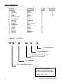
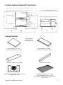
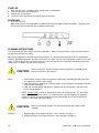
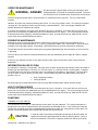
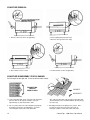
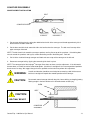
INSTALLATION & OPERATING
INSTRUCTIONS
for
IMPINGER® CONVEYOR OVENS
MODEL 1300 SERIES
TO BE SERVICED ONLY BY AUTHORIZED PERSONS
1300opsman
Part Number: 2810088
REV: 1/4/07
WARNING AND SAFETY INFORMATION
IMPORTANT
FOR YOUR SAFETY, DO NOT STORE OR USE GASOLINE OR OTHER FLAMMABLE VAPORS OR LIQUIDS
IN THE VICINITY OT THIS OR ANY OTHER APPLIANCE.
DO NOT SPRAY AEROSOLS IN THE VICINITY OF THIS APPLIANCE WHILE IT IS IN OPERATION.
WARNING: IMPROPER INSTALLATION, ADJUSTMENT, ALTERATION, SERVICE OR MAINTENANCE CAN
CAUSE PROPERTY DAMAGE, INJURY OR DEATH. READ THE INSTALLATION, OPERATING, AND
MAINTENANCE INSTRUCTIONS THOROUGHLY BEFORE INSTALLING OR SERVICING THIS EQUIPMENT.
•
•
•
•
•
•
•
Minimum clearances must be maintained from all walls and combustible materials.
Keep the oven area free and clear of combustible material.
Adequate clearance for air openings to the control chamber on both sides of the oven is required.
Do not obstruct the ventilation holes in the control boxes and covers as these provide cooling air for the controls.
The oven is to be operated only on the type of electricity as shown on the specification plate.
This manual should be retained for future reference.
The electrical wiring diagram is located under the control box covers.
WARRANTY
®
Lincoln Foodservice Products, LLC warrants to the original purchaser for use of each new Impinger Conveyor
Oven as follows: any part which proves to be defective in materials or workmanship within the warranty period will,
subject to the terms of this warranty, be repaired or replaced at Lincoln’s option. Repair or replacement to be done
by the assigned Lincoln Authorized Service Agency. Any claims under this warranty must be presented in writing to
Lincoln through the assigned Authorized Service Agency, promptly and within the warranty period.
For ovens installed in the United States and Canada, defective parts of the original equipment are warranted for
one year from the date of purchase and the cost of repair or replacement labor shall be at the expense of Lincoln
Foodservice Products, LLC for one year from date of purchase. (Purchase date must be within 24 months of
manufacturing date for warranty to be in effect.) If the date of purchase cannot be verified, then warranty shall not
exceed 18 months from date of manufacture.
For ovens installed in locations other than the United States or Canada, defective parts of the original equipment
are warranted for one year from the date of purchase and the cost of repair or replacement labor shall be at the
expense of Lincoln Foodservice Products, LLC for 90 days from date of purchase. (Purchase date must be within
24 months of manufacturing date for warranty to be in effect.)
This warranty shall not apply if the oven or any part is subjected to accident, casualty, alteration, misuse, abuse,
faulty installation, or if the date of manufacture is altered or removed.
The obligation of Lincoln Foodservice Products, LLC is limited to the above and except as expressly stated herein.
Lincoln Foodservice Products, LLC makes no guarantee or warranty, express or implied, including without limitation
®
warranties of fitness of merchant ability with respect to Impinger Conveyor Oven and Lincoln Foodservice
products, LLC has no other liability with respect thereto including without limitation, liability for incidental, special, or
consequential damages.
The following items are not covered by warranty: Any item that is defective because of utility services (power
surges, high and low voltage or improper connections); conveyor belt; replacement of fuses, bulbs, gaskets, and
motor brushes; adjustments and calibrations for temperatures, speed and air flows.
2
CounterTop - 1300 Series Ops Manual
PURCHASER’S RESPONSIBILITY
It is the responsibility of the purchaser to:
1. See that the electric services for the oven are installed on site in accordance with the manufacturers
specifications.
2. Unload, uncrate, and install the oven in its proper location in accordance with this installation operation manual.
3. See that the electric services are connected properly by a qualified installer of your choice. All such connections
must be in accordance with applicable code requirements. Refer to page 6 for specific code references.
TABLE OF CONTENTS
WARRANTY AND SAFETY INFORMATION…………………………………………………………………...………… 2
WARRANTY………………………………………………………………………………………………………………..… 2
PURCHASER’S RESPONSIBILITY…………………………………………………………………………………..…… 3
UTILITY SPECIFICATION – ELECTRIC……………………………………………………………………………..…… 3
AMBIENT TEMPERATURE REQUIREMENTS………………………………………………………………………...… 3
MODEL NUMBER KEY…………………………………………………………………………………………………..…. 4
EXTERIOR DIMENSIONS……………………………………………………………………………………………..…… 5
OVEN ACCESSORIES…………………………………………………………………………………………………..…. 5
CODE REFERENCES…………………………………………………………………………………………………….… 6
VENTILATION GUIDELINES……………………………………………………………………………………………..… 6
GENERAL INFORMATION……………………………………………………………………………………………….… 6
UNLOADING AND UNCRATING………………………………………………………………………………………...… 6
ASSEMBLY INSTRUCTIONS…………………………………………………………………………………………….… 7
STACKING INSTRUCTIONS……………………………………………………………………………………………..… 8
MOUNTING INSTRUCTIONS……………………………………………………………………………………….………9
OVEN START-UP AND SHUTDOWN…………………………………………………………………………………..… 10
CLEANING INSTRUCTIONS…………………………………………………………………………………………….… 10
PREVENTIVE MAINTENANCE…………………………………………………………………………………………….. 11
HOW TO OBTAIN SERVICE…………………………………………………………………………………………….…. 11
FUNCTIONS – THERMAL CUT-OUT SWITCH………………………………………………………………………….. 11
CONVEYOR REMOVAL……………………………………………………………………………………………….……. 12
CONVEYOR DISASSEMBLY FOR CLEANING………………………………………………………………….………. 12
CONVEYOR REASSMBLY……………………………………………………………………………………….………… 13
FINGER REMOVAL AND DISASSEMBLY…………………………………………………………………….…………. 14
FINGER COLUMNATING PLATE IDENTIFICATION……………………………………………………..…………. 15-16
®
IMPINGER CONCEPTS…………………………………………………………………………………..……………….. 17
APPENDIX A: LABEL DEFINITIONS………………………………………………………………………..…………. 18-19
UTILITY SPECIFICATION
®
IMPINGER CONVEYOR OVEN
Model
1300
1301
1302
1303
1304
1305
1306
1307
1308
1309
1310
1311
1312-xxx-E
1313-xxx-E
Input Rate
6 kW
6 kW
6 kW
6 kW
6 kW
6 kW
6 kW
6 kW
6 kW
6 kW
6 kW
6 kW
6 kW
6 kW
Voltage
200 VAC
208 VAC
240 VAC
220 VAC
240 VAC
380/220 VAC
415/240 VAC
200 VAC
380/220 VAC
415/240 VAC
220 VAC
380/220 VAC
400/230 VAC
400/230 VAC
Current
28 Amps
27 Amps
24 Amps
27 Amps
24 Amps
15 Amps
14 Amps
16 Amps
9 Amps
8 Amps
27 Amps
9 Amps
9 Amps
15 Amps
Phase
1
1
1
1
1
1
1
3
3
3
1
3
3
1
Hz
50/60 Hz
60 Hz
60 Hz
50 Hz
50 Hz
50 Hz
50 Hz
50/60 Hz
50 Hz
50 Hz
60 Hz
60 Hz
50 Hz
50 Hz
# of Wires
3
3
3
3
3
4
4
5
5
5
3
5
5
3
Agency Listing
NSF
UL, CSA, NSF
UL, CSA, NSF
NSF
NSF
DIN, NSF
NSF
NSF
NSF
NSF
DB Level
NSF, CE Certified
NSF, CE Certified
dba 70
dba 70
NOTE: Do not install this (these) oven(s) in any area with an ambient temperature in excess of 95° F / 35° C. Doing so
will cause damage to unit.
CounterTop - 1300 Series Ops Manual
3
MODEL NUMBER KEY
COUNTRY
LANGUAGE
CODE
1.
2.
3.
4.
5.
6.
7.
8.
9.
10.
11.
12.
13.
14.
15.
16.
French
German
Italian
Spanish
English
French
Portuguese
Danish
Dutch / French
Dutch
English
Greek
German
Finnish
Norwegian
Swedish
B
C
D
E
F
B
H
J
K
L
F
M
C
N
P
R
France
Germany
Italy
Spain
United Kingdom
Luxembourg
Portugal
Denmark
Belgium
Netherlands
Ireland
Greece
Austria
Finland
Norway
Sweden
NOT USED
A
I
O
Q
EXAMPLE: 1322-B00-EA
1312-
B
00- E
A
A = Advantage Style
E = EC Marked Units
00 = Special Unit Designation
(02 = All Stainless Unit)
B = Language
1312 = Main Model Number
NOTE: Date of manufacture is
stamped on the rating plate of each
oven at the end of the serial number.
Example: XXX…01-96
4
CounterTop - 1300 Series Ops Manual
EXTERIOR DIMENSIONS IMPINGER® OVEN MODELS
Top oven shown with conveyor #1353
Bottom oven shown with extended conveyor #1346
OVEN ACCESSORIES
NOTE: Optional
Columnating Plates
listed on pages 15-16.
#1341 Exit Shelf – 12” Length
#1343 Entry Incline Shelf – 12” Length
#1342 Exit Shelf – 4” Length
#1344 Entry Incline Shelf – 4” Length
#1352 Extended Baffle, Inlet and Outlet
#1345 Conveyor Endstop
#1950 Wall Receptacle NEMA 6-50 USA & Canada
(For Models 1301 & 1302)
#1346 Extended Conveyor 49 ¾” Length
#1353 Standard Conveyor 31” Length
We recommend entry and exit shelves on standard
length conveyor
CounterTop - 1300 Series Ops Manual
5
ELECTRICAL GROUNDING INSTRUCTIONS
!
WARNING
DOMESTIC:
As it pertains to model units 1300, 1301 and 1302 only, this appliance is equipped with a three-prong
(grounding) plug for your protection against shock hazard and should be plugged directly into a properly
grounded three-prong receptacle. Do not cut or remove the grounding prong from this plug.
!
WARNING
INT’L (CE):
This appliance must be properly grounded at time of installation. Failure to ensure that this equipment
is properly grounded can result in electrocution, dismemberment or fatal injury.
!
WARNING:
If the supply cord appears to be damaged, do not attempt to operate unit. Contact a service agent
or qualified electrician to repair.
ELECTRICAL CODE REFERENCE
IN USA
When installed, this appliance must be electrically grounded and its installation must comply with the National
Electric Code, ANSI-NFPA 70, latest version, the Manufacturer’s Installation Instructions, and applicable municipal
building codes.
IN CANADA
All electrical connections are to be made in accordance with CSA C22.1 – Canadian Electrical Code Part 1 and/or
local codes.
ALL OTHER COUNTRIES
Local electrical codes will prevail.
1. Strain Relief is provided with each oven. International Dealer/Distributors provide applicable power cord/plug
for each customer.
2. All pole disconnection switch 3mm open contact distance.
3. To prevent electrical shock, an equal potential bonding ground lug is provided in the back. This allows the oven
to be connected to an external bonding system.
4. If used as double stack and each oven has its own disconnection switch, all switches should be close together.
SPACING
The oven must have 6 inches (152 mm) of clearance from combustible surfaces. In case other equipment is
located on the right side of oven, a minimum clearance of 24 inches (609 mm) is required from that equipment.
FOR ALL OVENS: A 24-inch (609 mm) clearance at the rear of the oven must be obtainable for service access.
VENTILATION
Local codes prevail. These are the “authority having jurisdiction” as stated by the NATIONAL FIRE PROTECTION
ASSOCIATION, INC. in NFPA 96, latest edition.
GENERAL INFORMATION
®
The instructions that follow are intended as a guide for preparing for the installation of the Impinger Conveyor
oven.
First and foremost, each crate should be examined before signing the Bill of Lading to report any visible damage
caused by the trucker in transit and account for the number of crates.
IF THERE IS APPARENT DAMAGE: United States and Canada: Arrangements should be made to file a claim
against the carrier. As Interstate Commerce Regulations require that the claim must be initiated by the consignee.
All shipments to other countries: Freight terms will be developed and extended on an individual basis.
Proper and secure storage facilities should be arranged for the oven(s) if necessary to protect it from outdoor or
damp conditions at all times before installation.
UNCRATING
~ DO NOT LIFT EXCESSIVE WEIGHT ~
When you have all the crates unloaded, open the crates and remove the plastic covers. Inspect at once for
concealed damage. If anything appears to be damaged, contact the appropriate persons immediately to file a
damage claim. After completing this inspection, finish unpacking the oven and all other components. Move the
components inside near the area where they will be assembled in the order in which they will be assembled.
6
CounterTop - 1300 Series Ops Manual
IMPINGER® ASSEMBLY INSTRUCTIONS
INSTAL LEGS AS SHOWN
!
WARNING:
Legs MUST be installed to insure
proper operation!
!
CAUTION:
Oven must be operated on approved bases only.
Bottom unit must always be mounted on legs provided.
!
CAUTION:
Before applying power to oven, check to insure that the four (4)
finger assemblies and two (2) air duct panels (upper & lower) are
properly seated and have not become dislodged during shipment.
Air Duct Panel
(Upper)
FRONT OF
FINGER ASSEMBLY
PROPERLY INSTALLED
Air Duct Panel
(Lower)
INSIDE FRONT WALL OF OVEN
CounterTop - 1300 Series Ops Manual
7
IMPINGER® STACKING INSTRUCTIONS
FOR SINGLE AND DOUBLE-STACK OVENS
NOTE: When stacking
ovens, remove bottom
flue cap from top oven.
NOTE: Stack ovens so that the small “foot” on top oven fits into the “indentation” on the top of the bottom oven.
!
8
CAUTION:
If you use a double stack, please note that each oven has its own
disconnect switch. Make sure that all switches are in the “OFF”
position before beginning maintenance or cleaning.
CounterTop - 1300 Series Ops Manual
COUNTERTOP MOUNTING INSTRUCTIONS
Position the oven on the countertop and carefully mark the position of the rear legs. Remove the oven from the
countertop and position the mounting rings so that the large (center) hole is where the legs of the oven were
marked. Mark the position of the two small holes and remove the mounting rings. Install per instruction 1 or 2
below.
1. When installing on a heavy stainless steel countertop, use the four #10-32 x 3/8” machine screws. Use a .159”
diameter drill (#21) and drill through the countertop. Use a 10-32 tap through the holes. Using a screwdriver,
mount the rings in position. Set the oven on the countertop so that the rear legs are in the larger holes in the
mounting ring.
2. When installing on a plywood or composition board countertop, use the four #10 x ½” sheet metal screws. Use
a .169” diameter drill (#18) and drill at least ½” into the countertop. Using a screwdriver, mount the rings in
position. Set the oven on the countertop so that the rear legs are in the large holes in the mounting rings.
REAR
FRONT
Leg location for
®
Impinger Countertop Oven
CounterTop - 1300 Series Ops Manual
9
START-UP
1.
2.
3.
4.
Push switch to “ON.” The electric oven should come on immediately.
Turn oven dial to desired temperature.
Preheat oven for 30 minutes.
To set belt speed, adjust oven time dial to reach desired time.
SHUTDOWN
1. Push switch to “OFF.”
Note: Ovens prior to serial #3018980, fan continues to operate for approximately 20 minutes. Turning on and
off fan switch will reset the timer for an additional 20 minutes.
CLEANING INSTRUCTIONS
®
The Lincoln Impinger oven contains electrical components. Before cleaning the oven, switch off and disconnect
the oven from the electrical supply.
No electrical components should be subjected to moisture. It is therefore important that the oven is wiped down
carefully. NEVER throw buckets of water over the oven or subject it to pressure washing from a hose or a pressure
spray. If water or other liquid is spilled on the oven, make sure that none has entered the control box area before
switching on. If in doubt, call your service company.
!
DAILY:
CAUTION:
Oven must be cool. Do not use power-cleaning equipment, steel wool, or wire
brushes on stainless steel surfaces.
1. Clean exterior surfaces of the oven by wiping it down with a mild detergent and clean water,
or a commercial stainless steel cleaner.
2. Clean the interior by sweeping up all loose particles, then wash with a mild detergent solution
and rinse with clean water.
3. Clean the conveyor belt by wiping with a cleaning cloth or brushing with a soft wire brush.
Lincoln catalog #369217.
NOTE: DO NOT USE a caustic or alkaline base cleaner on interior of oven. This will ruin the
aluminized finish of the oven interior. On exterior of oven, removal of deposits of baked-on
splatter, oil, grease, or light discolorations may be removed with any of several commercial
cleaners. Consult with your local supplier.
!
WEEKLY:
10
CAUTION:
When using cleaning solutions, be sure they meet local and national health
standards.
1. Remove fingers, disassemble and clean. See instructions on page 14.
2. Remove conveyor, disassemble and clean. See instructions on page 12.
CounterTop - 1300 Series Ops Manual
OPERATOR MAINTENANCE
!
WARNING - DANGER:
Disconnect power supply before servicing or cleaning this oven.
Safeguard power so it cannot be accidentally restored. Failure to
do so could result in dismemberment, electrocution, or fatal injury.
Extensive engineering went into this oven to make it as maintenance free as possible. There is no lubrication
required.
However, to achieve the maximum efficiency of the oven, it is necessary to keep it clean. For cleaning instructions
see page 10. The frequency listed is only the factory’s recommendations. Your use and type of products will
actually determine the frequency of cleaning.
If the oven fails to operate, check the circuit breaker to be sure it is turned on. Also check the fuses on the back
panel to be sure that they are good before you call the Authorized Service Agency. The name and phone number
of the Authorized Service Agency should be located on the oven, or contact the factory at (260) 432-9511 for the
name of the nearest Authorized Service Agency.
PREVENTIVE MAINTENANCE
Although this oven has been designed to be as trouble free as possible, periodic Preventive Maintenance is
essential to maintain peak performance. It is necessary to keep the motors, fans, and electronics free of dirt, dust,
and debris to insure proper cooling. Overheating is detrimental to the life of all the components mentioned.
The periodic intervals for preventive cleaning may vary greatly depending upon the environment in which the oven
is operating.
You must discuss the need for Preventive Maintenance with your Authorized Service Agent to establish a proper
program.
If there are any questions that the service agent cannot answer, please contact the Lincoln Technical Service
department.
INFORMATION ON USE OF OVEN
®
As explained in “Concepts,” the Impinger Conveyor Oven functions by directing high velocity streams of heated air
directly upon the food products. Because air is the heat source, it is effective even on sensitive foods. Compares
®
to conventional ovens and even convection ovens, the cooking time of products in the Impinger Conveyor Oven
can be as much as two (2) to four (4) times faster. Several factors may affect the cooking time of any special
products such as:
1. Oven Temperature Setting
2. Conveyor Speed
We encourage you to experiment with the oven by trying different temperature settings and belt speeds.
HOW TO OBTAIN SERVICE
If the oven fails to operate, check the circuit breaker to be sure it is turned on. Also check the fuses on the back
panel to be sure that they are good before you call the Authorized Service Agency. The name and phone number
of the Authorized Service Agency should be located on the oven, or contact the factory at (260) 432-9511 for the
name of the nearest Authorized Service Agency.
FUNCTIONS
THERMAL CUT-OUT SWITCH
The CounterTop unit includes a “safety thermal cut-out switch” for your protection. This safety related device is
designed to insure that the CounterTop unit will not overheat and damage the unit. In the unlikely event that the
CounterTop unit would exceed the specified operating temperature range, the “safety thermal cut-out switch” will
activate, thus blocking power to the CounterTop unit and causing it to turn off.
!
CAUTION:
In order to avoid a hazard due to inadvertent resetting of the thermal cutout, this
appliance must not be supplied through an external switching device, such as a
timer or connected to a circuit that is regularly switched on and off by the utility.
CounterTop - 1300 Series Ops Manual
11
CONVEYOR REMOVAL
1. Remove extension shelves (if applicable).
2. Push coupling away from drive lugs.
3. Remove conveyor from oven cavity.
4. Reassemble in reverse order.
5. Install extension shelves (if applicable).
CONVEYOR DISASSEMBLY FOR CLEANING
Pull conveyor out the right end. Place on table or work surface.
CONNECTING
LINKS IN
FOUR PLACES
CORRECT
INCORRECT
1. Locate connecting links on the conveyor belt, turn belt to
place the links on the top left end of the conveyor –
approximately 8” (203 mm) from the shaft.
2. You can easily remove the connecting links by grasping
them with a pair of pliers and slipping the eye of the
connecting link over the wire of the other links.
12
Also, notice the direction of the opening on the other links.
The belt will have to be reinstalled with the opening facing
the same way.
3. Carefully pull out the belt, rolling it up as you go. After
you have it removed it may be placed in a pan of
detergent solution to soak. Rinse with clean water.
CounterTop - 1300 Series Ops Manual
CONVEYOR REASSEMBLY
CONVEYOR BELT INSTALLATION
BELT
CONVEYOR DRIVE
CORRECT
INCORRECT
1. Put conveyor belt back on by setting the rolled belt to the left of the conveyor and thread approximately 2/3 of
the belt over the bottom slider bed.
2. Put the loose end of the belt around the idler shaft and back on the conveyor. The belt must lie on top of the
upper conveyor slider bed.
NOTE: The belt should curl around the conveyor sprockets and lay flat on top of the sprockets. If the belting does
not curl around the sprockets and lay flat, remove the belting and turn the belting over. Reinstall.
3. Pull all of the slack belt through conveyor until both ends are on top of the conveyor on the left end.
4. Reconnect conveyor belt by slipping the connecting links back in place.
®
NOTE: The conveyor belt of the Impinger Conveyor Oven does not have a tension adjustment. If the belt would
become loose, a link will have to be removed to tighten. A belt that is too tight will also cause operational problems
due to excessive drag. We suggest that you have a qualified service technician perform this adjustment.
!
WARNING:
Careful consideration should be exercised prior to removing a belt link because a
belt that is too tight will impede the smooth operation of the conveyor.
!
CAUTION:
Do not work around conveyor belt with long hair, loose clothing, or dangling jewelry.
Getting caught in the belt could result in dismemberment or fatal injury.
OVEN
BELT
!
CAUTION:
BELT MAY BE HOT!
CONVEYOR
ASSEMBLY
CounterTop - 1300 Series Ops Manual
13
FINGERS – REMOVAL AND DISASSEMBLY FOR CLEANING
!
CAUTION:
Oven must be cool before proceeding.
DISASSEMBLY
RETAINING
TABS
1. Release ¼-turn fasteners (2 per panel) then
pull back the panel. Lift panel off lower
retaining tabs.
2. Lift finger assembly to clear hanger on front
wall of oven. Then slide to the rear and swing
out. Remove finger assembly from oven.
COLUMNATING PLATE
DISASSEMBLE FINGERS FOR CLEANING
3. Slide finger cover from housing. Lift out inner
Columnating Plate.
ORIFICE
PANEL
REASSEMBLY
4. Reassemble in reverse order.
NOTE: Check to insure that the holes in the
columnating plate are lined up with the holes in
the office panel.
5. Reinstall fingers in the oven. Be sure that they
are fully seated over the plenum flanges and
the holes are pointing toward the conveyor.
6. Reinstall cover panels (see #1).
INSIDE FRONT WALL OF OVEN
14
CounterTop - 1300 Series Ops Manual
MODEL 1301 & 1302
SERIAL #3002168
AND ABOVE
ALL OTHER MODELS
SERIAL #3001885
AND ABOVE
FINGER COVERS ARE MATCHED AND MAY BE INSTALLED IN ANY LOCATION
NOTE: Assembly numbers are stamped on the outer edge of the finger cover.
ASSEMBLY
NO. 1
ASSEMBLY
NO. 2
MODEL 1301 & 1302
SERIAL #3002167
AND BELOW
ASSEMBLY
NO. 3
ASSEMBLY
NO. 4
ALL OTHER MODELS
SERIAL #3001884
AND BELOW
FINGER ASSEMBLIES MUST BE INSTALLED AS SHOWN
IMPINGER® FINGER COLUMNATING PLATES
COLUMNATING PANEL #1368
APPEARANCE: Perforated metal with 6 rows of larger holes.
EFFECT: Maximum velocity and airflow. A relative comparison can
be made between a 1368/1508.
APPLICATION: 95% of all cooking applications will use these panels
®
in all four fingers. An Impinger CounterTop is shipped with #1368
panels in the top and bottom finger housing.
NOTE: All ICT’s will be shipped with this configuration unless you
specify otherwise.
CounterTop - 1300 Series Ops Manual
15
IMPINGER® FINGER COLUMNATING PLATES (CONT’D)
COLUMNATING PANEL #1349
APPEARANCE: Panel is made from solid metal with 6 rows of larger
holes, then covered with perforated metal.
EFFECT: Reduces air flow significantly. A relative comparison can
be made between a 1349/1736 (Low Profile).
COLUMNATING PANEL #1355
APPEARANCE: Panel is made from perforated metal. It has no
large orifice columnating holes.
EFFECT: Moderate velocity. A relative comparison can be made
between a 1355/1511.
COLUMNATING PANEL #1356
APPEARANCE: Panel is made from solid metal with only 2 rows of
holes open in one side of the panel; then the open holes are
covered with perforated metal.
EFFECT: Extreme reduction in airflow, 67% less than a #1349.
COLUMNATING PANEL #1360
APPEARANCE: Panel is made from solid metal with 6 rows of holes.
EFFECT: Less velocity than a #1368 or a #1355. A relative
comparison can be made between a 1360/1500.
COLUMNATING PANEL #1361
APPEARANCE: Panel made from solid blank plate, no holes.
EFFECT: This panel would create a complete block of air from any
®
one finger in the Impinger CounterTop. A relative comparison can
be made between the 1361/1501.
®
NOTE: The Impinger CounterTop was built with the basic idea that it would be ready out of the box – uncrate,
plug-in and cook! In all but 5% of your cooking applications you will do just that. You will not need to alter the ICT
set-up except for very special requirements.
Our objective here is to tell you about these alternate panels because they have gone through the “new product
release” process and are available to you for special applications in the field. As always, the Product Manager and
the Applied Technology Department will be here should you need further information or guidance.
!
16
CAUTION:
The smaller the interior chamber, the more critical the airflow balance. A panel change
in the ICT may cause front to back striping discrepancies for certain applications.
CounterTop - 1300 Series Ops Manual
CONCEPTS
®
The Impinger Conveyor Oven produced by Lincoln Foodservice Products, LLC utilizes a revolutionary cooking
concept called “AIR IMPINGEMENT.” It provides exceptional baked food product quality in far less time than
conventional devices on the market. The “AIR IMPINGEMENT” system directs a high velocity stream of heated air
at the food product being baked. This blast effect penetrates the boundary layer of air encircling the product and
heats the food more efficiently because the air concentrates heat on the product. Greater heat transfer rates, which
result in products baking two to four times faster than conventional means, are possible with “AIR IMPINGEMENT.”
The “AIR IMPINGEMENT” process develops the high velocity air stream with a specially designed fan that draws
super-heated air from a heat source (electric). This air is directed through a plenum chamber to patented “JET
FINGERS” which have hundreds of focused jetports that “impinge” the heated air onto the product surface. The
heated air is recycled to the heat source after striking the product, thus reducing energy consumption.
The “AIR IMPINGEMENT” process is tolerant enough for sensitive food products and effect proper crisping and
even browning of such products as they pass through the oven – because air is the medium that heats the food
product.
CounterTop - 1300 Series Ops Manual
17
APPENDIX A – LABEL DEFINITIONS
18
CounterTop - 1300 Series Ops Manual
APPENDIX A – LABEL DEFINITIONS (CONT’D)
CounterTop - 1300 Series Ops Manual
19
Lincoln Foodservice Products, LLC has developed a worldwide sales and service network second to none in our
industry. It is headed by a sales, service and marketing management staff of more than 60 seasoned foodservice
professionals. We manufacture and market Impinger Conveyor ovens, Wear-Ever and Centurion cookware, Redco
food slicers, cutters and wedgers, Fresh-O-Matic food warmers that are stocked by a national network of more than
1,400 distributors nationwide. Adding to this extensive dealer base, 74 master parts distributors supply more than
400 independent service agencies throughout the world. Those agencies employ nearly 1,200 service
representatives. The end result – a cohesive international network designed to serve every need of the
professional foodservice operation.
With the products, experience and service network that Lincoln provides, any foodservice operation can be sure
that expert assistance is always no more than a phone call away. For additional information on sales, service,
warranties and parts, just call the Lincoln National Service Manager at our Fort Wayne, Indiana headquarters.
We’ll be happy to assist!
Lincoln Foodservice Products, LLC
1111 North Hadley Road
Fort Wayne, Indiana 46804
United States of America
Telephone: (260) 459-8200
U.S. Fax: (888) 790-8193
Int’l Fax: (260) 436-0735
Service Hotline: (800) 678-9511
www.lincolnfp.com
20
CounterTop - 1300 Series Ops Manual