1
View Safety Info
SVM207-A
January, 2011
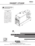
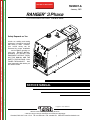
RANGER® 3 Phase
For use with machine code number:
11079 & 11419
Return to Master TOC
View Safety Info
View Safety Info
Safety Depends on You
Return to Master TOC
Return to Master TOC
RETURN TO MAIN MENU
Lincoln arc welding and cutting
equipment is designed and built
with safety in mind. However,
your overall safety can be
increased by proper installation
. . . and thoughtful operation on
your part. DO NOT INSTALL,
OPERATE OR REPAIR THIS
EQUIPMENT WITHOUT READING THIS MANUAL AND THE
SAFETY PRECAUTIONS CONTAINED THROUGHOUT. And,
most importantly, think before you
act and be careful.
View Safety Info
Return to Master TOC
SERVICE MANUAL
Copyright © Lincoln Global Inc.
• World's Leader in Welding and Cutting Products •
• Sales and Service through Subsidiaries and Distributors Worldwide •
Cleveland, Ohio 44117-1199 U.S.A. TEL: 216.481.8100 FAX: 216.486.1751 WEB SITE: www.lincolnelectric.com
SAFETY
Return to Master TOC
i
i
WARNING
CALIFORNIA PROPOSITION 65 WARNINGS
Diesel engine exhaust and some of its constituents
The engine exhaust from this product contains
are known to the State of California to cause canchemicals known to the State of California to cause
cer, birth defects, and other reproductive harm.
cancer, birth defects, or other reproductive harm.
The Above For Gasoline Engines
The Above For Diesel Engines
ARC WELDING can be hazardous. PROTECT YOURSELF AND OTHERS FROM POSSIBLE SERIOUS INJURY OR DEATH.
KEEP CHILDREN AWAY. PACEMAKER WEARERS SHOULD CONSULT WITH THEIR DOCTOR BEFORE OPERATING.
Return to Master TOC
Return to Master TOC
Read and understand the following safety highlights. For additional safety information, it is strongly recommended that you
purchase a copy of “Safety in Welding & Cutting - ANSI Standard Z49.1” from the American Welding Society, P.O. Box 351040,
Miami, Florida 33135 or CSA Standard W117.2-1974. A Free copy of “Arc Welding Safety” booklet E205 is available from the
Lincoln Electric Company, 22801 St. Clair Avenue, Cleveland, Ohio 44117-1199.
BE SURE THAT ALL INSTALLATION, OPERATION, MAINTENANCE AND REPAIR PROCEDURES ARE PERFORMED ONLY BY QUALIFIED INDIVIDUALS.
FOR ENGINE
powered equipment.
1.h. To avoid scalding, do not remove the
radiator pressure cap when the engine is
hot.
1.a. Turn the engine off before troubleshooting and maintenance
work unless the maintenance work requires it to be running.
____________________________________________________
1.b.Operate engines in open, well-ventilated
areas or vent the engine exhaust fumes
outdoors.
____________________________________________________
1.c. Do not add the fuel near an open flame welding arc or when the engine is running. Stop
the engine and allow it to cool before refueling to prevent spilled fuel from vaporizing on
contact with hot engine parts and igniting. Do
not spill fuel when filling tank. If fuel is spilled,
wipe it up and do not start engine until fumes
have been eliminated.
____________________________________________________
1.d. Keep all equipment safety guards, covers and devices in position and in good repair.Keep hands, hair, clothing and tools
away from V-belts, gears, fans and all other moving parts
when starting, operating or repairing equipment.
____________________________________________________
Return to Master TOC
1.e. In some cases it may be necessary to remove safety
guards to perform required maintenance. Remove
guards only when necessary and replace them when the
maintenance requiring their removal is complete.
Always use the greatest care when working near moving
parts.
___________________________________________________
1.f. Do not put your hands near the engine fan.
Do not attempt to override the governor or
idler by pushing on the throttle control rods
while the engine is running.
ELECTRIC AND
MAGNETIC FIELDS
may be dangerous
2.a. Electric current flowing through any conductor causes
localized Electric and Magnetic Fields (EMF). Welding
current creates EMF fields around welding cables and
welding machines
2.b. EMF fields may interfere with some pacemakers, and
welders having a pacemaker should consult their physician
before welding.
2.c. Exposure to EMF fields in welding may have other health
effects which are now not known.
2.d. All welders should use the following procedures in order to
minimize exposure to EMF fields from the welding circuit:
2.d.1. Route the electrode and work cables together - Secure
them with tape when possible.
2.d.2. Never coil the electrode lead around your body.
2.d.3. Do not place your body between the electrode and
work cables. If the electrode cable is on your right
side, the work cable should also be on your right side.
2.d.4. Connect the work cable to the workpiece as close as
possible to the area being welded.
___________________________________________________
1.g. To prevent accidentally starting gasoline engines while
turning the engine or welding generator during maintenance
work, disconnect the spark plug wires, distributor cap or
magneto wire as appropriate.
2.d.5. Do not work next to welding power source.
RANGER® 3 PHASE
SAFETY
Return to Master TOC
Return to Master TOC
ii
ELECTRIC SHOCK can kill.
ARC RAYS can burn.
3.a. The electrode and work (or ground) circuits
are electrically “hot” when the welder is on.
Do not touch these “hot” parts with your bare
skin or wet clothing. Wear dry, hole-free
gloves to insulate hands.
4.a.
Use a shield with the proper filter and cover
plates to protect your eyes from sparks and
the rays of the arc when welding or observing
open arc welding. Headshield and filter lens
should conform to ANSI Z87. I standards.
3.b. Insulate yourself from work and ground using dry insulation.
Make certain the insulation is large enough to cover your full
area of physical contact with work and ground.
4.b. Use suitable clothing made from durable flame-resistant
material to protect your skin and that of your helpers from
the arc rays.
In addition to the normal safety precautions, if welding
must be performed under electrically hazardous
conditions (in damp locations or while wearing wet
clothing; on metal structures such as floors, gratings or
scaffolds; when in cramped positions such as sitting,
kneeling or lying, if there is a high risk of unavoidable or
accidental contact with the workpiece or ground) use
the following equipment:
• Semiautomatic DC Constant Voltage (Wire) Welder.
• DC Manual (Stick) Welder.
• AC Welder with Reduced Voltage Control.
4.c. Protect other nearby personnel with suitable, non-flammable
screening and/or warn them not to watch the arc nor expose
themselves to the arc rays or to hot spatter or metal.
3.c. In semiautomatic or automatic wire welding, the electrode,
electrode reel, welding head, nozzle or semiautomatic
welding gun are also electrically “hot”.
3.d. Always be sure the work cable makes a good electrical
connection with the metal being welded. The connection
should be as close as possible to the area being welded.
3.e. Ground the work or metal to be welded to a good electrical
(earth) ground.
3.f. Maintain the electrode holder, work clamp, welding cable and
welding machine in good, safe operating condition. Replace
damaged insulation.
3.g. Never dip the electrode in water for cooling.
Return to Master TOC
ii
3.h. Never simultaneously touch electrically “hot” parts of
electrode holders connected to two welders because voltage
between the two can be the total of the open circuit voltage
of both welders.
3.i. When working above floor level, use a safety belt to protect
yourself from a fall should you get a shock.
3.j. Also see Items 6.c. and 8.
FUMES AND GASES
can be dangerous.
5.a. Welding may produce fumes and gases
hazardous to health. Avoid breathing these
fumes and gases.When welding, keep
your head out of the fume. Use enough
ventilation and/or exhaust at the arc to keep
fumes and gases away from the breathing zone. When
welding
with
electrodes
which
require
special
ventilation such as stainless or hard facing (see
instructions on container or MSDS) or on lead or
cadmium plated steel and other metals or coatings
which produce highly toxic fumes, keep exposure as
low as possible and within applicable OSHA PEL and ACGIH
TLV limits using local exhaust or mechanical ventilation. In
confined spaces or in some circumstances, outdoors, a respirator may be required. Additional precautions are also
required when welding on galvanized steel.
5. b. The operation of welding fume control equipment is affected
by various factors including proper use and positioning of the
equipment, maintenance of the equipment and the specific
welding procedure and application involved. Worker exposure level should be checked upon installation and periodically thereafter to be certain it is within applicable OSHA PEL
and ACGIH TLV limits.
5.c. Do not weld in locations near chlorinated hydrocarbon vapors
coming from degreasing, cleaning or spraying operations.
The heat and rays of the arc can react with solvent vapors to
form phosgene, a highly toxic gas, and other irritating products.
5.d. Shielding gases used for arc welding can displace air and
cause injury or death. Always use enough ventilation,
especially in confined areas, to insure breathing air is safe.
Return to Master TOC
5.e. Read and understand the manufacturer’s instructions for this
equipment and the consumables to be used, including the
material safety data sheet (MSDS) and follow your
employer’s safety practices. MSDS forms are available from
your welding distributor or from the manufacturer.
5.f. Also see item 1.b.
RANGER® 3 PHASE
SAFETY
Return to Master TOC
iii
WELDING and CUTTING
SPARKS can cause fire or
explosion.
6.a. Remove fire hazards from the welding area.If
this is not possible, cover them to prevent the welding sparks
from starting a fire. Remember that welding sparks and hot
materials from welding can easily go through small cracks
and openings to adjcent areas. Avoid welding near hydraulic
lines. Have a fire extinguisher readily available.
6.b. Where compressed gases are to be used at the job site,
special precautions should be used to prevent hazardous
situations. Refer to “Safety in Welding and Cutting” (ANSI
Standard Z49.1) and the operating information for the
equipment being used.
Return to Master TOC
6.c. When not welding, make certain no part of the electrode
circuit is touching the work or ground. Accidental contact can
cause overheating and create a fire hazard.
6.d. Do not heat, cut or weld tanks, drums or containers until the
proper steps have been taken to insure that such procedures
will not cause flammable or toxic vapors from substances
inside. They can cause an explosion even though they have
been “cleaned”. For information, purchase “Recommended
Safe Practices for the Preparation for Welding and Cutting of
Containers and Piping That Have Held Hazardous
Substances”, AWS F4.1 from the American Welding Society
(see address above).
6.e. Vent hollow castings or containers before heating, cutting or
welding. They may explode.
iii
CYLINDER may explode
if damaged.
7.a. Use only compressed gas cylinders
containing the correct shielding gas for the
process used and properly operating
regulators designed for the gas and
pressure used. All hoses, fittings, etc. should be suitable for
the application and maintained in good condition.
7.b. Always keep cylinders in an upright position securely
chained to an undercarriage or fixed support.
7.c. Cylinders should be located:
• Away from areas where they may be struck or subjected to
physical damage.
• A safe distance from arc welding or cutting operations and
any other source of heat, sparks, or flame.
7.d. Never allow the electrode, electrode holder or any other
electrically “hot” parts to touch a cylinder.
7.e. Keep your head and face away from the cylinder valve outlet
when opening the cylinder valve.
7.f. Valve protection caps should always be in place and hand
tight except when the cylinder is in use or connected for
use.
7.g. Read and follow the instructions on compressed gas
cylinders, associated equipment, and CGA publication P-l,
“Precautions for Safe Handling of Compressed Gases in
Cylinders,” available from the Compressed Gas Association
1235 Jefferson Davis Highway, Arlington, VA 22202.
Return to Master TOC
6.f. Sparks and spatter are thrown from the welding arc. Wear oil
free protective garments such as leather gloves, heavy shirt,
cuffless trousers, high shoes and a cap over your hair. Wear
ear plugs when welding out of position or in confined places.
Always wear safety glasses with side shields when in a
welding area.
6.g. Connect the work cable to the work as close to the welding
area as practical. Work cables connected to the building
framework or other locations away from the welding area
increase the possibility of the welding current passing through
lifting chains, crane cables or other alternate circuits. This can
create fire hazards or overheat lifting chains or cables until
they fail.
FOR ELECTRICALLY
powered equipment.
8.a. Turn off input power using the disconnect
switch at the fuse box before working on
the equipment.
8.b. Install equipment in accordance with the U.S. National
Electrical Code, all local codes and the manufacturer’s
recommendations.
8.c. Ground the equipment in accordance with the U.S. National
Electrical Code and the manufacturer’s recommendations.
6.h. Also see item 1.c.
6.I. Read and follow NFPA 51B “ Standard for Fire Prevention
During Welding, Cutting and Other Hot Work”, available from
NFPA, 1 Batterymarch Park,PO box 9101, Quincy, Ma
022690-9101.
Return to Master TOC
6.j. Do not use a welding power source for pipe thawing.
Refer to http://www.lincolnelectric.com/safety for additional safety information.
RANGER® 3 PHASE
SAFETY
Return to Master TOC
Return to Master TOC
Return to Master TOC
Return to Master TOC
iv
iv
PRÉCAUTIONS DE SÛRETÉ
6. Eloigner les matériaux inflammables ou les recouvrir afin de
prévenir tout risque d’incendie dû aux étincelles.
Pour votre propre protection lire et observer toutes les instructions
et les précautions de sûreté specifiques qui parraissent dans ce
manuel aussi bien que les précautions de sûreté générales suivantes:
7. Quand on ne soude pas, poser la pince à une endroit isolé de
la masse. Un court-circuit accidental peut provoquer un
échauffement et un risque d’incendie.
Sûreté Pour Soudage A L’Arc
1. Protegez-vous contre la secousse électrique:
a. Les circuits à l’électrode et à la piéce sont sous tension
quand la machine à souder est en marche. Eviter toujours
tout contact entre les parties sous tension et la peau nue
ou les vétements mouillés. Porter des gants secs et sans
trous pour isoler les mains.
b. Faire trés attention de bien s’isoler de la masse quand on
soude dans des endroits humides, ou sur un plancher metallique ou des grilles metalliques, principalement dans
les positions assis ou couché pour lesquelles une grande
partie du corps peut être en contact avec la masse.
c. Maintenir le porte-électrode, la pince de masse, le câble de
soudage et la machine à souder en bon et sûr état defonctionnement.
d.Ne jamais plonger le porte-électrode dans l’eau pour le
refroidir.
e. Ne jamais toucher simultanément les parties sous tension
des porte-électrodes connectés à deux machines à souder
parce que la tension entre les deux pinces peut être le total
de la tension à vide des deux machines.
f. Si on utilise la machine à souder comme une source de
courant pour soudage semi-automatique, ces precautions
pour le porte-électrode s’applicuent aussi au pistolet de
soudage.
2. Dans le cas de travail au dessus du niveau du sol, se protéger
contre les chutes dans le cas ou on recoit un choc. Ne jamais
enrouler le câble-électrode autour de n’importe quelle partie du
corps.
8. S’assurer que la masse est connectée le plus prés possible de
la zone de travail qu’il est pratique de le faire. Si on place la
masse sur la charpente de la construction ou d’autres endroits
éloignés de la zone de travail, on augmente le risque de voir
passer le courant de soudage par les chaines de levage,
câbles de grue, ou autres circuits. Cela peut provoquer des
risques d’incendie ou d’echauffement des chaines et des
câbles jusqu’à ce qu’ils se rompent.
9. Assurer une ventilation suffisante dans la zone de soudage.
Ceci est particuliérement important pour le soudage de tôles
galvanisées plombées, ou cadmiées ou tout autre métal qui
produit des fumeés toxiques.
10. Ne pas souder en présence de vapeurs de chlore provenant
d’opérations de dégraissage, nettoyage ou pistolage. La
chaleur ou les rayons de l’arc peuvent réagir avec les vapeurs
du solvant pour produire du phosgéne (gas fortement toxique)
ou autres produits irritants.
11. Pour obtenir de plus amples renseignements sur la sûreté, voir
le code “Code for safety in welding and cutting” CSA Standard
W 117.2-1974.
PRÉCAUTIONS DE SÛRETÉ POUR
LES MACHINES À SOUDER À
TRANSFORMATEUR ET À
REDRESSEUR
3. Un coup d’arc peut être plus sévère qu’un coup de soliel, donc:
a. Utiliser un bon masque avec un verre filtrant approprié ainsi
qu’un verre blanc afin de se protéger les yeux du rayonnement de l’arc et des projections quand on soude ou
quand on regarde l’arc.
b. Porter des vêtements convenables afin de protéger la peau
de soudeur et des aides contre le rayonnement de l‘arc.
c. Protéger l’autre personnel travaillant à proximité au
soudage à l’aide d’écrans appropriés et non-inflammables.
4. Des gouttes de laitier en fusion sont émises de l’arc de
soudage. Se protéger avec des vêtements de protection libres
de l’huile, tels que les gants en cuir, chemise épaisse, pantalons sans revers, et chaussures montantes.
1. Relier à la terre le chassis du poste conformement au code de
l’électricité et aux recommendations du fabricant. Le dispositif
de montage ou la piece à souder doit être branché à une
bonne mise à la terre.
2. Autant que possible, I’installation et l’entretien du poste seront
effectués par un électricien qualifié.
3. Avant de faires des travaux à l’interieur de poste, la debrancher à l’interrupteur à la boite de fusibles.
4. Garder tous les couvercles et dispositifs de sûreté à leur place.
5. Toujours porter des lunettes de sécurité dans la zone de
soudage. Utiliser des lunettes avec écrans lateraux dans les
zones où l’on pique le laitier.
RANGER® 3 PHASE
Return to Master TOC
Return to Master TOC
Return to Master TOC
v
SAFETY
Electromagnetic Compatibility (EMC)
Conformance
Products displaying the CE mark are in conformity with European Community Council Directive of 15 Dec
2004 on the approximation of the laws of the Member States relating to electromagnetic compatibility,
2004/108/EC. It was manufactured in conformity with a national standard that implements a harmonized
standard: EN 60974-10 Electromagnetic Compatibility (EMC) Product Standard for Arc Welding Equipment.
It is for use with other Lincoln Electric equipment. It is designed for industrial and professional use.
Introduction
All electrical equipment generates small amounts of electromagnetic emission. Electrical emission may be
transmitted through power lines or radiated through space, similar to a radio transmitter. When emissions
are received by other equipment, electrical interference may result. Electrical emissions may affect many
kinds of electrical equipment; other nearby welding equipment, radio and TV reception, numerical controlled
machines, telephone systems, computers, etc. Be aware that interference may result and extra precautions
may be required when a welding power source is used in a domestic establishment.
Installation and Use
The user is responsible for installing and using the welding equipment according to the manufacturer’s
instructions. If electromagnetic disturbances are detected then it shall be the responsibility of the user of the
welding equipment to resolve the situation with the technical assistance of the manufacturer. In some cases
this remedial action may be as simple as earthing (grounding) the welding circuit, see Note. In other cases
it could involve construction of an electromagnetic screen enclosing the power source and the work complete with associated input filters. In all cases electromagnetic disturbances must be reduced to the point
where they are no longer troublesome.
Note: The welding circuit may or may not be earthed for safety reasons according to national
codes. Changing the earthing arrangements should only be authorized by a person who is
competent to access whether the changes will increase the risk of injury, e.g., by allowing
parallel welding current return paths which may damage the earth circuits of other equipment.
Assessment of Area
Before installing welding equipment the user shall make an assessment of potential electromagnetic problems in the surrounding area. The following shall be taken into account:
a) other supply cables, control cables, signaling and telephone cables; above, below and adjacent to the
welding equipment;
b) radio and television transmitters and receivers;
c) computer and other control equipment;
d) safety critical equipment, e.g., guarding of industrial equipment;
Return to Master TOC
e) the health of the people around, e.g., the use of pacemakers and hearing aids;
f) equipment used for calibration or measurement
g) the immunity of other equipment in the environment. The user shall ensure that other equipment being
used in the environment is compatible. This may require additional protection measures;
h) the time of day that welding or other activities are to be carried out.
RANGER® 3 PHASE
v
Return to Master TOC
vi
SAFETY
Electromagnetic Compatibility (EMC)
The size of the surrounding area to be considered will depend on the structure of the building and other
activities that are taking place. The surrounding area may extend beyond the boundaries of the premises.
Methods of Reducing Emissions
Return to Master TOC
Return to Master TOC
Mains Supply
Welding equipment should be connected to the mains supply according to the manufacturer’s recommendations. If interference occurs, it may be necessary to take additional precautions such as filtering of the mains
supply. Consideration should be given to shielding the supply cable of permanently installed welding equipment, in metallic conduit or equivalent. Shielding should be electrically continuous throughout its length. The
shielding should be connected to the welding power source so that good electrical contact is maintained
between the conduit and the welding power source enclosure.
Maintenance of the Welding Equipment
The welding equipment should be routinely maintained according to the manufacturer’s recommendations.
All access and service doors and covers should be closed and properly fastened when the welding equipment is in operation. The welding equipment should not be modified in any way except for those changes
and adjustments covered in the manufacturers instructions. In particular, the spark gaps of arc striking and
stabilizing devices should be adjusted and maintained according to the manufacturer’s recommendations.
Welding Cables
The welding cables should be kept as short as possible and should be positioned close together, running at
or close to floor level.
Equipotential Bonding
Bonding of all metallic components in the welding installation and adjacent to it should be considered.
However, metallic components bonded to the work piece will increase the risk that the operator could
receive a shock by touching these metallic components and the electrode at the same time. The operator
should be insulated from all such bonded metallic components.
Earthing of the Workpiece
Where the workpiece is not bonded to earth for electrical safety, not connected to earth because of its size
and position, e.g., ships hull or building steelwork, a connection bonding the workpiece to earth may reduce
emissions in some, but not all instances. Care should be taken to prevent the earthing of the workpiece
increasing the risk of injury to users, or damage to other electrical equipment. Where necessary, the connection of the workpiece to earth should be made by a direct connection to the workpiece, but in some
countries where direct connection is not permitted, the bonding should be achieved by suitable capacitance,
selected according to national regulations.
Return to Master TOC
Screening and Shielding
Selective screening and shielding of other cables and equipment in the surrounding area may alleviate
problems of interference. Screening of the entire welding installation may be considered for special applications. 1
_________________________
1 Portions of the preceding text are contained in EN 60974-10: “Electromagnetic Compatibility (EMC) product standard for arc welding equipment.”
RANGER® 3 PHASE
vi
I
- MASTER TABLE OF CONTENTS FOR ALL SECTIONS RETURN TO MAIN MENU
Page
Safety . . . . . . . . . . . . . . . . . . . . . . . . . . . . . . . . . . . . . . . . . . . . . . . . . . . . . . . . . . . . . . . . . . . . . . . . . . .i-iv
Installation . . . . . . . . . . . . . . . . . . . . . . . . . . . . . . . . . . . . . . . . . . . . . . . . . . . . . . . . . . . . . . . . . .Section A
Operation . . . . . . . . . . . . . . . . . . . . . . . . . . . . . . . . . . . . . . . . . . . . . . . . . . . . . . . . . . . . . . . . . .Section B
Accessories . . . . . . . . . . . . . . . . . . . . . . . . . . . . . . . . . . . . . . . . . . . . . . . . . . . . . . . . . . . . . . . .Section C
Maintenance . . . . . . . . . . . . . . . . . . . . . . . . . . . . . . . . . . . . . . . . . . . . . . . . . . . . . . . . . . . . . . . .Section D
Theory of Operation . . . . . . . . . . . . . . . . . . . . . . . . . . . . . . . . . . . . . . . . . . . . . . . . . . . . . . . . . .Section E
Troubleshooting and Repair . . . . . . . . . . . . . . . . . . . . . . . . . . . . . . . . . . . . . . . . . . . . . . . . . . .Section F
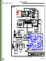
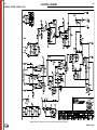
Electrical Diagrams . . . . . . . . . . . . . . . . . . . . . . . . . . . . . . . . . . . . . . . . . . . . . . . . . . . . . . . . . .Section G
Parts Manual . . . . . . . . . . . . . . . . . . . . . . . . . . . . . . . . . . . . . . . . . . . . . . . . . . . . . . . . . . . . . . . . . . .P-496
RANGER® 3 PHASE
I
Return to Master TOC
A-1
TABLE OF CONTENTS - INSTALLATION SECTION
A-1
Installation . . . . . . . . . . . . . . . . . . . . . . . . . . . . . . . . . . . . . . . . . . . . . . . . . . . . . . . . . . . . . . . . . . . . . . . . . . . . . .A-1
Technical Specifications.............................................................................................................................A-2
Safety Precautions.....................................................................................................................................A-3
Machine Grounding ...................................................................................................................................A-3
Spark Arrestor ............................................................................................................................................A-3
Towing .......................................................................................................................................................A-3
Vehicle Mounting .......................................................................................................................................A-4
Pre-Operation Service ...............................................................................................................................A-4
Fuel ... ..................................................................................................................................................A-4
Return to Master TOC
Oil .........................................................................................................................................................A-4
Battery Connections .............................................................................................................................A-4
Welding Output Cables..............................................................................................................................A-5
Angle of Operation.....................................................................................................................................A-5
Lifting .........................................................................................................................................................A-5
High Altitude Operation..............................................................................................................................A-5
Muffler Relocation ......................................................................................................................................A-5
Location/Ventilation....................................................................................................................................A-6
Connection of Wire Feeders ......................................................................................................................A-6
Additional Safety Precautions....................................................................................................................A-6
Welder Operation.......................................................................................................................................A-6
Motor Starting ............................................................................................................................................A-8
Stand-by Power Connections ....................................................................................................................A-8
Auxiliary Power While Welding ..................................................................................................................A-8
Connection of RANGER® 3PHASE to Premises Wiring (Drawing) ..........................................................A-9
Extension Cord Recommendations .........................................................................................................A-10
Electrical Devices used w/RANGER® 3 PHASE ....................................................................................A-10
Return to Master TOC
Return to Master TOC
Auxiliary Power ..........................................................................................................................................A-7
RANGER® 3 PHASE
INSTALLATION
Return to Master TOC
Return to Section TOC
A-2
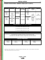
TECHNICAL SPECIFICATIONS - RANGER® 3 PHASE (K2337-1 & K2337-2)
INPUT - GASOLINE ENGINE
Description
Make/Model
Return to Master TOC
K2337-1
Kohler
CH20S
Return to Section TOC
A-2
2 cylinder
4 Cycle
Air-Cooled
Gasoline
Engine.
Aluminum Alloy
with Cast Iron
Liners,
Electronic
Ignition
K2337-2
Kohler
CH23S
Horsepower
20 HP @
3600 RPM
Operating
Displacement
Speed (RPM)
cu. in.
(cu.cm.)
38(624)
Kohler
CH20S
High Idle 3700
Full Load 3500
41(674)
Kohler
CH23S
23 HP @
3600 RPM
Low Idle 2200
Starting
System
Capacities
12VDC
Battery
Electric Start
Group 58
Battery
(435 cold
cranking
amps)
Fuel:
9 Gal (34 L)
Lubricating Oil:
2.0 Qts. (1.9 L)
RATED OUTPUT @ 104°F (40°C)- WELDER
Welding Output
AC Constant Current 225A / 25V / 100%
DC Constant Current 210A / 25V / 100%
DC Constant Voltage 200A / 20V / 100%
RATED OUTPUT @ 104°F (40°C)- GENERATOR
Return to Master TOC
Return to Master TOC
Return to Section TOC
Return to Section TOC
Auxiliary Power
1
11,500 Watts Peak,10,500 Watts Continuous, 3 Phase 60 Hz AC,480V
10,500 Watts Peak, 9500 Watts Continuous, Single Phase 60 Hz AC,120V/240V
PHYSICAL DIMENSIONS
HEIGHT
WIDTH
DEPTH
30.3 in.
770 mm
19.1 in.
485 mm
42.3 in.
1074 mm
WEIGHT
538 lbs.
(244kg)
1. Output rating in watts is equivalent to volt - amperes at unity factor.Output voltage is within +/-10% at all loads up to rated capacity.
When welding available auxiliary power will be reduced.
RANGER® 3 PHASE
INSTALLATION
Return to Master TOC
Return to Master TOC
Return to Section TOC
Return to Section TOC
A-3
SAFETY PRECAUTIONS
WARNING
Do not attempt to use this equipment until you
have thoroughly read the engine manufacturer’s
manual supplied with your welder. It includes
important safety precautions, detailed engine
starting, operating and maintenance instructions,
and parts lists.
-----------------------------------------------------------------------ELECTRIC SHOCK can kill.
• Do not touch electrically live parts or
electrode with skin or wet clothing.
• Insulate yourself from work and
ground
• Always wear dry insulating gloves.
-----------------------------------------------------------------------ENGINE EXHAUST can kill.
• Use in open, well ventilated areas or
vent exhaust outside.
-----------------------------------------------------------------------MOVING PARTS can injure.
• Do not operate with doors open or
guards off.
• Stop engine before servicing.
• Keep away from moving parts.
------------------------------------------------------------------------
Return to Master TOC
Return to Section TOC
See additional warning information at the
front of this operator’s manual.
----------------------------------------------------------MACHINE GROUNDING
Because this portable engine driven welder / generator
creates it’s own power, it is not necessary to connect
it’s frame to an earth ground, unless the machine is
connected to premises wiring (your home, shop, etc.).
WARNING
Where this engine driven welder is connected to
premises wiring such as that in your home or shop, it’s
frame must be connected to the system earth ground.
See further connection instructions in the section entitled “Standby Power Connections”, as well as the article on grounding in the latest National Electrical Code
and the local code.
In general, if the machine is to be grounded, it should
be connected with a #8 or larger copper wire to a solid
earth ground such as a metal water pipe going into the
ground for at least ten feet and having no insulated
joints, or to the metal framework of a building which
has been effectively grounded. The National Electrical
Code lists a number of alternate means of grounding
electrical equipment. A machine grounding stud
marked with the symbol
is provided on the front of
the welder.
SPARK ARRESTER
Some federal, state, or local laws may require that
gasoline engines be equipped with exhaust spark
arresters when they are operated in certain locations
where unarrested sparks may present a fire hazard.
The standard muffler included with this welder does not
qualify as a spark arrester. When required by local regulations, the K894-1 spark arrester must be installed
and properly maintained.
CAUTION
TOWING
• be grounded to the frame of the welder using a
grounded type plug, or be double insulated.
Return to Master TOC
When this welder is mounted on a truck or trailer, it’s
frame must be electrically bonded to the metal frame of
the vehicle. Use a #8 or larger copper wire connected
between the machine grounding stud and the frame of
the vehicle.
An incorrect arrester may lead to damage to the
engine or adversely affect performance.
------------------------------------------------------------------------
To prevent dangerous electric shock, other equipment to which this engine driven welder supplies
power must:
Return to Section TOC
A-3
Do not ground the machine to a pipe that carries
explosive or combustible material.
------------------------------------------------------------------------
The recommended trailer for use with this equipment
for road, in-plant and yard towing by a vehicle(1) is
Lincoln’s K957-1. If the user adapts a non-Lincoln trailer, he must assume responsibility that the method of
attachment and usage does not result in a safety hazard nor damage the welding equipment. Some of the
factors to be considered are as follows:
1. Design capacity of trailer vs. weight of Lincoln equipment and likely additional attachments.
2. Proper support of, and attachment to, the base of
the welding equipment so there will be no undue
stress to the framework.
RANGER® 3 PHASE
INSTALLATION
Return to Master TOC
Return to Section TOC
A-4
3. Proper placement of the equipment on the trailer to
insure stability side to side and front to back when
being moved and when standing by itself while
being operated or serviced.
4. Typical conditions of use, i.e., travel speed; roughness of surface on which the trailer will be operated;
environmental conditions.
5. Conformance with federal, state and local
laws(1)
(1) Consult applicable federal, state and local laws regarding specific requirements for use on public highways.
VEHICLE MOUNTING
A-4
FUEL
Fill the fuel tank with clean, fresh, lead-free gasoline.
Observe fuel gauge while filling to prevent overfilling.
WARNING
• Damage to the fuel tank may cause
fire or explosion. Do not drill holes
in or weld to the RANGER®®
10,000 or the RANGER®® 10,000
PLUS base.
-----------------------------------------------------------------------
Return to Master TOC
Return to Section TOC
WARNING
Improperly mounted concentrated loads may
cause unstable vehicle handling and tires or other
components to fail.
• Only transport this Equipment on serviceable
vehicles which are rated and designed for such
loads.
• Distribute, balance and secure loads so vehicle
is stable under conditions of use.
• Do not exceed maximum rated loads for components such as suspension, axles and tires.
• Mount equipment base to metal bed or frame of
vehicle.
• Follow vehicle manufacture’s instructions.
------------------------------------------------------------------------
OIL
LUBRICATION SYSTEM CAPACITY
(INCLUDING FILTER)
Kohler CH20S / CH23S - 2.0 Quarts (1.9 Liters)
The RANGER® 3 PHASE is shipped with the engine
crankcase filled with SAE 10W-30 oil. Check the oil
level before starting the engine. If it is not up to the full
mark on the dip stick, add oil as required. Make certain that the oil filler cap is tightened securely. Refer to
the engine Owner’s Manual for specific oil recommendations.
Return to Master TOC
Return to Master TOC
Return to Section TOC
Return to Section TOC
PRE-OPERATION SERVICE
CAUTION
CAUTION
READ the engine operating and maintenance
instructions supplied with this machine.
WARNING
• Stop engine while fueling.
• Do not smoke when fueling.
• Keep sparks and flame away from
tank.
• Do not leave unattended while fueling.
• Wipe up spilled fuel and allow fumes
to clear before starting engine.
GASOLINE • Do not overfill tank, fuel expansion
can cause fire may cause overflow.
or explosion.
BATTERY CONNECTIONS
Use caution as the electrolyte is a strong
acid that can burn skin and damage eyes.
----------------------------------------------------------------------This welder is shipped with the negative battery cable
disconnected. Make sure that the Engine Switch is in
the “STOP” position and attach the disconnected
cable securely to the negative battery terminal before
attempting to operate the machine. If the battery is discharged and does not have enough power to start the
engine, see the battery charging instructions in the
Battery section.
NOTE: This machine is furnished with a wet charged
battery; if unused for several months, the battery may require a booster charge. Be careful
to charge the battery with the correct polarity.
GASOLINE FUEL ONLY
------------------------------------------------------------------------
RANGER® 3 PHASE
INSTALLATION
Return to Master TOC
Return to Master TOC
Return to Section TOC
Return to Section TOC
A-5
WELDING OUTPUT CABLES
A-5
WARNING
With the engine off, connect the electrode and work
cables to the studs provided. These connections
should be checked periodically and tightened if necessary. Loose connections will result in overheating of the
output studs.
When welding at a considerable distance from the
welder, be sure you use ample size welding cables.
Listed below are copper cable sizes recommended for
the rated current and duty cycle. Lengths stipulated are
the distance from the welder to work and back to the
welder again. Cable sizes are increased for greater
lengths primarily for the purpose of minimizing cable
voltage drop.
• Lift only with equipment of adequate lifting capacity.
• Be sure machine is stable when
lifting.
• Do not lift this machine using
lift bale if it is equipped with a
heavy accessory such as trailer
or gas cylinder.
FALLING
• Do not lift machine if lift bale is
EQUIPMENT can
damaged.
cause injury.
• Do not operate machine while
suspended from lift bale.
------------------------------------------------------------------------
HIGH ALTITUDE OPERATION
At higher altitudes, elder output de-rating may be necessary.
TOTAL COMBINED LENGTH OF
ELECTRODE AND WORK CABLES
225 Amps
100% Duty Cycle
0-100 Ft.
1 AWG
100-200 Ft.
1 AWG
200-250 Ft.
1/0 AWG
For maximum rating, de-rate the welder output 3.5% for
every 1000ft. (305m) above 3000ft. (914m).
If operation will consistently be at altitudes above 5,000 ft.
(1525m), a carburetor jet designed for high altitudes should
be installed. This will result in better fuel economy, cleaner
exhaust and longer spark plug life. It will not give increased
power. Contact your local authorized engine service shop for
high altitude jet kits that are available from the engine manufacturer.
Return to Master TOC
Return to Section TOC
ANGLE OF OPERATION
CAUTION
Internal combustion engines are designed to run in a
level condition which is where the optimum performance is achieved. The maximum angle of operation
for the engine is 15 degrees from horizontal in any
direction. If the engine is to be operated at an angle,
provisions must be made for checking and maintaining
the oil at the normal (FULL) oil capacity in the
crankcase in a level condition.
Do not operate with a high altitude jet installed at altitudes below 5000 ft. This will result in the engine running
too lean and result in higher engine operating temperatures which can shorten engine life.
--------------------------------------------------------------------------------
Muffler Relocation
WARNING
When operating at an angle, the effective fuel capacity
will be slightly less than the specified 9 gallons.
• Shut off welder and allow muffler to cool before touch-
Return to Master TOC
Return to Section TOC
LIFTING
The RANGER® 3 PHASE weighs approximately 575
lbs. with a full tank of gasoline. A lift bail is mounted to
the machine and should always be used when lifting
the machine.
ing muffler.
-------------------------------------------------------------------------------The RANGER® 3 PHASE is shipped with the exhaust coming out on the left side. The exhaust can be changed to the
opposite side by removing the two screws that hold the
exhaust port cover in place and installing the cover on the
opposite side. (Operating the RANGER® 3 Phase machine
without the covers in place will result in a higher noise level
and no increase in machine output.)
RANGER® 3 PHASE
INSTALLATION
Return to Master TOC
Return to Section TOC
A-6
c.
LOCATION / VENTILATION
The welder should be located to provide an unrestricted flow of clean, cool air to the cooling air inlets and to
avoid heated air coming out of the welder recirculating
back to the cooling air inlet. Also, locate the welder so
that engine exhaust fumes are properly vented to an
outside area.
STACKING
RANGER® 3 PHASE machines cannot be stacked.
CONNECTION OF LINCOLN ELECTRIC
WIRE FEEDERS
Return to Master TOC
Return to Master TOC
Return to Section TOC
Return to Section TOC
WARNING
Shut off welder before making any electrical
connections.
-----------------------------------------------------------------------WIRE FEED (CONSTANT VOLTAGE)
CONNECTION OF LN-15 ACROSS-THE-ARC WIRE
FEEDER
The LN-15 has an internal contactor and the electrode
is not energized until the gun trigger is closed. When
the gun trigger is closed the wire will begin to feed and
the welding process is started.
Note: LN-15 Control Cable model will not work with
the RANGER® 3PHASE.
a. Shut the welder off.
b. Connect the electrode cable from the LN-15 to
the“ELECTRODE” terminal of the welder. Connect
the work cable to the “TO WORK” terminal of the
welder.
c. Set the Polarity switch to the desired polarity, either
DC (-) or DC (+).
d. Attach the single lead from the front of the LN-15
to work using the spring clip at the end of the lead.
This is a control lead to supply current to the wire
feeder motor; it does not carry welding current.
e. Set the “RANGE” switch to the “WIRE FEED-CV”
position
f. Place the Engine switch in the “High Idle” position.
g. Adjust the wire feed speed at the LN-15 and adjust
the welding voltage with the output “CONTROL” at
the welder. Output “CONTROL” must be set above 3.
Return to Master TOC
CONNECTION OF THE LN-25 / LN25PRO / LN-25
PRO DUAL
Return to Section TOC
A-6
Note: LN-25PRO Dual Control Cable model will not
work with the RANGER® 3 PHASEe.
a. Shut the welder off.
b. Connect the electrode cable from the LN-25 to
the“ELECTRODE” terminal of the welder. Connect
the work cable to the “TO WORK” terminal of the
welder.
Position the welder “Polarity” switch to the desired
polarity, either DC (-) or DC (+).
d. Position the “RANGE” switch to the “WIRE FEED”
position.
e. Attach the single lead from the LN-25 control box
to the work using the spring clip on the end of the
lead - it carries no welding current.
f. Place the engine switch in the “AUTO” position.
g. Adjust wire feed speed at the LN-25 and adjust the
welding voltage with the output “CONTROL” at the
welder.
NOTE: The welding electrode is energized at all times,
unless an LN-25 with built-in contactor is used.
If the output “CONTROL” is set below “3”, the
LN-25 contactor may not pull in.
CONNECTION OF K930-2 TIG MODULE TO THE
RANGER® 3 PHASE.
The TIG Module is an accessory that provides high
frequency and shielding gas control for AC and DC
GTAW (TIG) welding. See IM528 supplied with the
TIG Module for installation instructions.
NOTE: The TIG Module does not require the use of a
high frequency bypass capacitor. However, if
any other high frequency equipment is used, a
Bypass Capacitor Kit (T12246) must be
installed in the RANGER® 3 PHASE.
INSTRUCTIONS
ADDITIONAL SAFETY PRECAUTIONS
Always operate the welder with the roof and case sides
in place as this provides maximum protection from
moving parts and assures proper cooling air flow.
Read and understand all Safety Precautions before
operating this machine. Always follow these and any
other safety procedures included in this manual and in
the Engine Owner’s Manual.
WELDER OPERATION
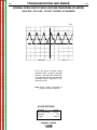
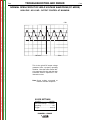
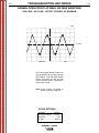
WELDER OUTPUT
• Maximum Open Circuit Voltage at 3700 RPM is
80 Volts RMS.
• Duty Cycle is the percentage of time the load is
being applied in a 10 minute period. For example, a
60% duty cycle represents 6 minutes of load and 4
minutes of no load in a 10 minute period. Duty Cycle
for the RANGER® 3 PHASE is 100%.
RANGER® 3 PHASE
Constant Current
225 Amps AC @ 25 Volts
210 Amps DC @ 25 Volts
Constant Voltage
200 Amps DC @ 20 Volts
RANGER® 3 PHASE
INSTALLATION
Return to Master TOC
Return to Master TOC
Return to Master TOC
Return to Section TOC
Return to Section TOC
Return to Section TOC
A-7
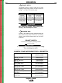
AUXILIARY POWER
A-7
120 V GFCI DUPLEX RECEPTACLES
CAUTION
Do not connect any plugs that connect to the
power receptacles in parallel.
-----------------------------------------------------------------------Start the engine and set the “IDLER” control switch to
the “High Idle” mode. Set the “CONTROL” to 10.
Voltage is now correct at the receptacles for auxiliary
power. This must be done before a tripped GFCI
receptacle can be reset properly. See the MAINTENANCE section for more detailed information on testing and resetting the GFCI receptacle.
The RANGER® 3 PHASE can provide both three
phase and single phase power, up to 11,500 watts of
480 volts AC, three phase 60Hz power for peak use,
and up to 10,500 watts of 480 volts AC, three phase
60Hz power for continuous use, up to 10,500 watts of
120/240 volts AC, single phase 60Hz power for peak
use, and up to 9,500 watts of 120/240 volt AC, single
phase 60Hz power for continuous use. The front of the
machine includes four receptacles for connecting the
AC power plugs; one 20 amp 480 volt 3 phase NEMA
receptacle, one 50 amp 120/240 volt NEMA 14-50R
receptacle and two 20 amp 120 volt NEMA 5-20R
receptacles. Output voltage is within +/-10% at all
loads up to rated capacity. Do not use 3 phase power
and single phase power simultaneously. All auxiliary
power is protected by cuircuit breakers.
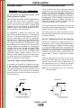
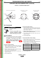
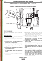
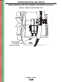
120/240 VOLT DUAL VOLTAGE RECEPTACLE
The 120/240 volt receptacle can supply up to 40 amps
of 240 volt power to a two wire circuit, up to 40 amps
of 120 volts power from each side of a three wire circuit (up to 80 amps total). Do not connect the 120 volt
circuits in parallel. Current sensing for the automatic
idle feature is only in one leg of the three wire circuit as
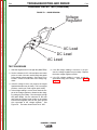
shown in Figure A.1.
A GFCI (Ground Fault Circuit Interrupter) electrical
receptacle is a device to protect against electric shock
should a piece of defective equipment connected to it
develop a ground fault. If this situation should occur,
the GFCI will trip, removing voltage from the output of
the receptacle. If a GFCI receptacle is tripped see the
MAINTENANCE section for detailed information on
testing and resetting it. A GFCI receptacle should be
properly tested at least once every month.
The 120V auxiliary power receptacles should only be
used with three wire grounded type plugs or approved
double insulated tools with two wire plugs.
The current rating of any plug used with the system
must be at least equal to the current load through the
associated receptacle.
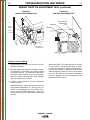
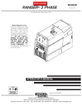
480 VOLT 3 PHASE RECEPTACLE WITH GROUND
The 480 volt receptacle can supply 12.6 amps of 3
phase power, or up to 15 amps of single phase power.
A NEMA L16-20P plug is required to use this receptacle. The ground (GND) connection is connected to the
machine frame, it is NOT the neutral of the three phase
connection, and should under no circumstances be
connected to the neutral of any 3 phase load. Do not
connect 480V 3 phase to single phase premises
wiring.
If 480 volt single phase load is to be run, the X lead
must be one of the leads in the circuit in order for the
automatic idle to function. Using a NEMA plug L1620P, connect either X and Y or X and Z to the receptacle, as well as the machine ground. See Figure A.2.
NOTE: Use of 3-Phase AC power is not recommended while welding.
FIGURE A.1
FIGURE A.2
Y
GND
Return to Master TOC
Return to Section TOC
480 V
X
Z
120 V
240 V
120 V*
GND
(FOR ALL SINGLE AND
THREE PHASE LOADS)
*Current Sensing for Automatic Idle.
(Receptacle viewed from front of Machine)
RANGER® 3 PHASE
INSTALLATION
Return to Master TOC
Return to Section TOC
A-8
All auxiliary power is protected by circuit breakers with
the following values:
The 120V has 20 amp circuit breakers for each duplex
receptacle. The 240V has 50 amp circuit breakers for
each hot lead going the 240V receptacle.
The 480V 3 phase circuit breaker / switch is a 3 phase,
15 amp circuit breaker.
Ground Wire
Periodically check the ground wire at plugs, power
cords and auxiliary loads to ensure that the grounding
circuit is intact and connected.
Return to Master TOC
Return to Master TOC
Return to Section TOC
Return to Section TOC
MOTOR STARTING
Most 1.5 hp AC single phase motors can be started if
there is no load on the motor or other load connected
to the machine, since the full load current rating of a
1.5 hp motor is approximately 20 amperes (10
amperes for 240 volt motors). The motor may be run at
full load when plugged into only one side of the duplex
receptacle. Larger motors through 2 hp can be run provided the receptacle rating as previously stated is not
exceeded. This may necessitate 240V operation only.
Switch rating must be the same or greater than the
customer’s premises disconnect and service overcurrent protection.
2. Take necessary steps to assure load is limited to
the capacity of the RANGER® 3 PHASE by
installing a 40 amp 240V double pole circuit breaker. Maximum rated load for the 240V auxiliary is 40
amperes. Loading above 40 amperes will reduce
output voltage below the allowable -10% of rated
voltage which may damage appliances or other
motor-driven equipment.
3. Install a 50 amp 120/240V plug (NEMA type 14-50)
to the Double Pole Circuit Breaker using No. 8, 4
conductor cable of the desired length. (The 50 amp
120/240V plug is available in the optional plug kit.)
4. Plug this cable into the 50 amp 120/240V receptacle on the RANGER® 3 PHASE case front.
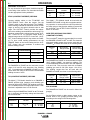
Simultaneous welding and power loads are permitted
by following Table I. The permissible currents shown
assume that current is being drawn from either the
120V or 240V supply (not both at the same time). Also,
the “Output Control” is set at “10” for maximum auxiliary power.
TABLE A.1
SIMULTANEOUS WELDING AND POWER***
Output Selector
Setting
STANDBY POWER CONNECTIONS
The RANGER® 3 PHASE is suitable for temporary,
standby, or emergency power using the engine manufacturer’s recommended maintenance schedule.
WARNING
Return to Master TOC
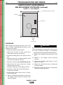
1. Install a double pole, double throw switch between
the power company meter and the premises disconnect.
AUXILIARY POWER WHILE WELDING
The 480 volt 3 phase output of the RANGER® 3
PHASE is capable of running most 480VAC 3 phase
motors up to 10HP. A 10HP motor must be started with
no load on the motor and no other load connected to
the machine, since the full load current of a 10HP
480VAC 3 phase motor is approximately 12.5 amps.
Refer to the reconnect phase output to any load, the
ground at the 3 phase receptacle is NOT the neutral of
3 phase connection, and should under no circumstance be connected to the neutral of any 3 phase
load.
The RANGER® 3 PHASE can be permanently
installed as a standby power unit for 240V-3 wire, single phase 40 ampere service.
Return to Section TOC
A-8
(Connections must be made by a licensed electrician
who can determine how the 120/240V power can be
adapted to the particular installation and comply with
all applicable electrical codes.) The following information can be used as a guide by the electrician for most
applications (refer also to the connection diagram
shown in Figure A.1).
------------------------------------------------------------------------
Permissible Power
Watts (Unity Power
Permissible Auxiliary
Current in Amperes
Factor)
@ 120V *-or- @ 240V
Max. Stick or Wire
Feed Setting
None
0
0
145 Stick Setting
4500
38
23
90 Stick Setting
6500
54**
27
NO WELDING
9500
80**
40
* Each duplex receptacle is limited to 20 amps.
** Not to exceed 40A per 120VAC branch circuit
***
when splitting the 240 VAC output.
Use of 3-Phase AC power is not recommended
while welding.
RANGER® 3 PHASE
INSTALLATION
Return to Master TOC
Return to Section TOC
A-9
A-9
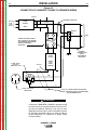
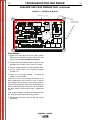
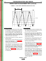
Figure A.3
CONNECTION OF RANGER® 3 PHASE TO PREMISES WIRING
240 VOLT
GROUNDED CONDUCTOR
POWER
240 Volt
60 Hz.
3-Wire
Service
120 VOLT
COMPANY
120 VOLT
METER
NEUTRAL
BUS
Return to Master TOC
Return to Section TOC
N
DOUBLE POLE DOUBLE THROW
SWITCH RATING TO BE THE SAME
AS OR GREATER THAN PREMISES
SERVICE OVERCURRENT
PROTECTION.
Return to Master TOC
Return to Section TOC
GROUND
40 AMP
240 VOLT
50 AMP, 120/240
VOLT PLUG
NEMA TYPE 14-50
240 VOLT
Return to Master TOC
PREMISES
DISCONNECT AND
SERVICE
OVERCURRENT
PROTECTION
DOUBLE
POLE
CIRCUIT
BREAKER
GND
N
50 AMP, 120/240 VOLT
RECEPTACLE
NOTE: No. 6 COPPER CONDUCTOR CABLE SEE
NATIONAL ELECTRICAL CODE FOR ALTERNATE WIRE
SIZE RECOMMENDATIONS.
WARNING
Return to Section TOC
LOAD
Connection of RANGER® 3 PHASE to premises wiring
must be done by a licensed electrician and must comply with the National Electrical Code and all other
applicable electrical codes. See the Installation Section
for important information about not using the 480V 3
Phase Receptacle for connection to Single Phase
Premises Wiring.
RANGER® 3 PHASE
INSTALLATION
Return to Master TOC
Return to Master TOC
Return to Master TOC
Return to Section TOC
Return to Section TOC
Return to Section TOC
A-10
A-10
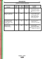
ELECTRICAL DEVICE USE WITH THE RANGER® 3 PHASE
Type
Common Electrical Devices
Possible Concerns
Resistive
Heaters, toasters, incandescent
light bulbs, electric range, hot
pan, skillet, coffee maker.
NONE
Capacitive
TV sets, radios, microwaves,
appliances with electrical control.
Voltage spikes or high voltage
regulation can cause the capacitative elements to fail. Surge
protection, transient protection,
and additional loading is recommended for 100% fail-safe operation. DO NOT RUN THESE
DEVICES WITHOUT ADDITIONAL RESISTIVE TYPE
LOADS.
Inductive
Single-phase induction motors,
drills, well pumps, grinders, small
refrigerators, weed and hedge
trimmers
These devices require large
current inrush for starting.
Some synchronous motors may
be frequency sensitive to attain
maximum output torque, but
they SHOULD BE SAFE from
any frequency induced failures.
Capacitive/Inductive
Computers, high resolution TV sets,
complicated electrical equipment.
An inductive type line conditioner along with transient and
surge protection is required, and
liabilities still exist. DO NOT
USE THESE DEVICES WITH A
RANGER® 3 PHASE
The Lincoln Electric Company is not responsible for any damage to electrical components improperly connected
to the RANGER® 3 PHASE machine
Return to Master TOC
Return to Section TOC
RANGER® 3 PHASE Extension Cord Length Recommendations
(Use the shortest length extension cord possible sized per the following table.)
Current Voltage Load
(Amps) Volts (Watts)
15
120
1800
20
120
2400
15
240
3600
20
240
4800
40
240
9500
Maximum Allowable Cord Length in ft. (m) for Conductor Size
12 AWG
10 AWG
8 AWG
6 AWG
175
(38)
(23)
(53)
(12)
125
40
75
138
(27)
(15)
(42)
(9)
88
30
50
(18)
350
(69)
(46)
(107)
(23)
225
75
150
275
(53)
(30)
(84)
(18)
175
60
100
150
(27)
(15)
(46)
90
50
14 AWG
(9)
30
60
Conductor size is based on maximum 2.0% voltage drop.
RANGER® 3 PHASE
4 AWG
(91)
300
(69)
225
(183)
600
(137)
450
(69)
225
Return to Master TOC
B-1
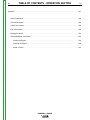
TABLE OF CONTENTS - OPERATION SECTION
B-1
Operation . . . . . . . . . . . . . . . . . . . . . . . . . . . . . . . . . . . . . . . . . . . . . . . . . . . . . . . . . . . . . . . . . . . . . . . . . . . . . .B-1
Safety Precautions . . . . . . . . . . . . . . . . . . . . . . . . . . . . . . . . . . . . . . . . . . . . . . . . . . . . . . . . . . . . . . . . . . . .B-2
General Description . . . . . . . . . . . . . . . . . . . . . . . . . . . . . . . . . . . . . . . . . . . . . . . . . . . . . . . . . . . . . . . . . . .B-2
Case Front Controls . . . . . . . . . . . . . . . . . . . . . . . . . . . . . . . . . . . . . . . . . . . . . . . . . . . . . . . . . . . . . . . . . . .B-2
Fuel Consumption . . . . . . . . . . . . . . . . . . . . . . . . . . . . . . . . . . . . . . . . . . . . . . . . . . . . . . . . . . . . . . . . . . . .B-3
Starting/Shutdown Instructions . . . . . . . . . . . . . . . . . . . . . . . . . . . . . . . . . . . . . . . . . . . . . . . . . . . . . . . . . . .B-6
Starting the Engine . . . . . . . . . . . . . . . . . . . . . . . . . . . . . . . . . . . . . . . . . . . . . . . . . . . . . . . . . . . . . . . .B-6
Stopping the Engine . . . . . . . . . . . . . . . . . . . . . . . . . . . . . . . . . . . . . . . . . . . . . . . . . . . . . . . . . . . . . . .B-6
Break-in Period . . . . . . . . . . . . . . . . . . . . . . . . . . . . . . . . . . . . . . . . . . . . . . . . . . . . . . . . . . . . . . . . . . .B-6
Return to Master TOC
Return to Master TOC
Return to Master TOC
Welding Processes . . . . . . . . . . . . . . . . . . . . . . . . . . . . . . . . . . . . . . . . . . . . . . . . . . . . . . . . . . . . . . . . . . . .B-4
RANGER® 3 PHASE
Return to Master TOC
Return to Master TOC
Return to Section TOC
Return to Section TOC
B-2
OPERATION
SAFETY PRECAUTIONS
Do not attempt to use this equipment until you
have thoroughly read the engine manufacturer’s
manual supplied with your welder. It includes
important safety precautions, detailed engine
starting, operating and maintenance instructions,
and parts lists.
-----------------------------------------------------------------------ELECTRIC SHOCK can kill.
• Do not touch electrically live parts or
electrode with skin or wet clothing.
• Insulate yourself from work and
ground
• Always wear dry insulating gloves.
WELDER CONTROLS - FUNCTION AND
OPERATION
ENGINE SWITCH
The engine switch is used to Start the Engine, Select
High Idle or Auto Idle while the engine is running, and
stop the Engine.
When placed in the “OFF”
position, the ignition
circuit is de-energized to shut down the engine.
When held in the “START”
starter motor is energized.
Return to Section TOC
Return to Master TOC
Return to Master TOC
position, the engine
• Always operate the welder with the hinged door
closed and the side panels in place.
When in “HIGH IDLE” (
) position, the engine will
run continuously at high idle.
• Read carefully the Safety Precautions page
before operating this machine. Always follow
these and any other safety procedures included
in this manual and in the Engine Instruction
Manual.
------------------------------------------------------------------------
When in “AUTO IDLE” (
/
) position, the engine
will run continuously and the idler operates as follows:
•
Welding
GENERAL DESCRIPTION
When the electrode touches the work, the welding
arc is initiated and the engine accelerates to full
speed.
The RANGER® 3 PHASE is a twin-cylinder, gasoline
driven, multiprocess arc welder and AC power generator. It is built in a heavy gauge steel case for durability
on the job site.
After welding ceases (and no auxiliary power is
being drawn), the engine will return to low idle
after approximately 10 to 14 seconds.
•
Return to Section TOC
B-2
Auxiliary Power
With the engine running at low idle and auxiliary
power for lights or tools is drawn (approximately
100-150 watts or greater) from the receptacles,
the engine will accelerate to high speed. If no
power is being drawn from the receptacles (and
not welding) for 10-14 seconds, the idler reduces
the engine speed to low idle.
RANGER® 3 PHASE
OPERATION
Return to Master TOC
Return to Section TOC
B-3
“
B-3
RANGE” SWITCH
The “Range” switch is used to select one of three
amperage ranges with generous overlap for Stick/TIG
welding, or one Wire Feed welding range.
Process
Range Setting
STICK/TIG
(constant current)
(3 range settings)
Current Range
90 Max.
50 to 90 Amps
145 Max.
70 to 145 Amps
210DC/225AC Max. 120 to 210 (DC) 225(AC)
WIRE FEED
(constant voltage)
(one range setting)
15 to 25V
Up to 200 Amps
Return to Master TOC
Return to Section TOC
CAUTION
Never change the “RANGE” Switch setting while
welding. This will damage the switch.
-----------------------------------------------------------------------“
CONTROL” DIAL
Provides a fine welding current adjustment within the
Range Switch settings in the STICK mode and welding
voltage control with the Range switch set in the wire
feed mode.
POLARITY SWITCH
Provides three selectable welding polarities:
AC, DC+ & DC-
Return to Master TOC
Return to Master TOC
Return to Section TOC
Return to Section TOC
CAUTION
Never change the Polarity switch setting while welding.
This will damage the switch.
------------------------------------------------------------------------------------------------
RANGER® 3 PHASE APPROXIMATE FUEL CONSUMPTION
KOHLER
CH20S or CH23S
Low Idle - No Load
2200 RPM
High Idle - No Load
3700 RPM
AC CC Weld Output
225 Amps @ 25 Volts
DC CC Weld Output
210 Amps @ 25 Volts
DC CV Weld Output
200 Amps @ 20 Volts
Auxiliary Power Single Phase
9,500 Watts
Auxiliary Power 3 Phase
10,500 Watts
.35 Gallons/Hour
(1.34 Liters/Hour)
.76 Gallons/Hour
(2.86 Liters/Hour)
1.23 Gallons/Hour
(4.64 Liters/Hour)
1.38 Gallons/Hour
(5.21 Liters/Hour)
1.22 Gallons/Hour
(4.60 Liters/Hour)
1.52 Gallons/Hour)
(5.77 Liters/Hour)
1.64Gallons/Hour)
(6.23 Liters/Hour)
RANGER® 3 PHASE
OPERATION
Return to Master TOC
Return to Master TOC
Return to Master TOC
Return to Section TOC
Return to Section TOC
Return to Section TOC
B-4
WELDING PROCESS
SETTINGS FOR 1% THORIATED TUNGSTEN
For any electrodes the procedures should be kept within the rating of the machine. For electrode information
see the appropriate Lincoln publication.
Return to Master TOC
TUNGSTEN
DIAMETER (in.)
1/8
3/32
1/16
RANGE SWITCH
SETTINGS
APPROXIMATE
CURRENT RANGE
90, 145, or 210
90 or 145
90 or 145
80 - 225 Amps
50 - 180 Amps
45 - 120 Amps
STICK (CONSTANT CURRENT) WELDING
Connect welding cables to the "TO WORK” and
"ELECTRODE” studs. Start the engine. Set the
"Polarity” switch to the desired polarity. The “RANGE”
switch markings indicate the maximum current for that
range as well as the typical electrode size for that
range. The “OUTPUT” Control provides fine adjustment of the welding current within the select range. For
maximum output within a selected range set the “OUTPUT” Control at 10. For minimum output within a
selected range set the “OUTPUT” Control at 5. (“OUTPUT” Control settings below 5 may reduce arc stability) For best overall welding performance set the
“RANGE” Switch to the lowest setting and the OUTPUT” Control near the maximum to achieve the
desired welding current.
RANGE SETTING
TYPICAL
CURRENT RANGE
ELECTRODE SIZE
90 MAX.
3/32
50 TO 90 AMPS
125 MAX.
1/8
70 TO 145 AMPS
210(DC)/225(AC)
MAX.
5/32
120 TO 210(DC),
225(AC) AMPS
The RANGER® 3 PHASE can be used with a broad
range of AC and DC stick electrodes. See “Welding
Tips 1” included with the RANGER 3 PHASE for electrodes within the rating of this unit and recommended
welding currents of each.
The K930-[ ] TIG Module installed on a RANGER 3
PHASE provides high frequency and shielding gas
control for AC and DC GTAW (TIG) welding processes.
The TIG Module allows full range output control. After
flow time is adjustable from 0 to 55 seconds.
SETTINGS FOR PURE TUNGSTEN
TUNGSTEN
DIAMETER (in.)
1/8
3/32
1/16
RANGE SWITCH
SETTINGS
90 or 145
90 or 145
90
The K930-[ ] TIG Module should be used with the
RANGER® 3 PHASE on high idle to maintain satisfactory operation. It can be used in the AUTO position but
the delay going to flow idle after welding is ceased will
be increased if the AFTER FLOW CONTROL is set
above 10 seconds.
WIRE FEED WELDING PROCESSES
(CONSTANT VOLTAGE)
The Innershield® electrode recommended for use with
the RANGER 3 PHASE is NR®-212-MP. The electrode
sizes and welding ranges that can be used with the
RANGER® 3 PHASE are shown in the following table:
Diameter
(in.)
.035
.045
.068
APPROXIMATE
CURRENT RANGE
80 - 150 Amps
45 - 130 Amps
40 - 80 Amps
Wire Speed
Range In./Min.
80 - 110
70 - 130
40 - 90
Approximate
Current Range
75A to 120A
120A to 170A
125A to 210A
The RANGER® 3 PHASE is recommended for limited
“MIG” welding (GMAW - gas metal arc welding). The
recommended electrodes are.030” and .035”SuperArc
L-50 and L-56. They must be used with a blended
shielding gas such as C25 (75% Argon - 25% CO2).
The welding ranges that can be used with the
RANGER 3 PHASE are shown in the following table:
Diameter
(in.)
TIG (CONSTANT CURRENT) WELDING
When using the RANGER® 3 PHASE for AC TIG welding of aluminum, the following settings and electrodes
are recommended:
Return to Section TOC
B-4
.030
.035
Wire Speed
Range In./Min.
80 - 110
70 - 130
Approximate
Current Range
75A to 120A
120A to 170A
ARC GOUGING
The RANGER® 3 PHASE can be used for limited arc
gouging.
Set the Range switch to adjust output current to the
desired level for the gouging electrode being used
according to the ratings in the following table:
CARBON DIAMETER (in)
1/8
5/32
3/16
RANGER® 3 PHASE
CURRENT RANGE (DC, electrode positive)
30 - 60 Amps
90 - 150 Amps
200 - 250 Amps
OPERATION
Return to Master TOC
Return to Master TOC
Return to Master TOC
Return to Master TOC
Return to Section TOC
Return to Section TOC
Return to Section TOC
Return to Section TOC
B-5
B-5
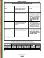
SUMMARY OF WELDING PROCESSES
PROCESS
CONTROL
CABLE
USED
IDLE
MODE
ELECTRODE
WHEN NOT
WELDING
TO START
WELDING
STICK
No
AUTO
Hot
Touch electrode to work.
Welding starts immediately
and engine goes to high
idle.
WIRE FEED, LN-25 WITH
INTERNAL CONTACTOR
No
AUTO
Cold
Press gun trigger, LN-25
contactor closes. Welding
starts immediately and
engine goes to high idle.
NOTE: Output Control
must be set above “3”
TIG, TIG MODULE WITH
WITH CONTACTOR KIT
CONTROL CABLE, & ARC
START SWITCH
Yes
High
Cold
Press Arc Start Switch
contactor closes,
welding starts immediately.
WIRE FEED, LN-15
ACROSS the ARC
(has internal contactor)
No
Auto
Cold
Press gun trigger.
LN-15 contactor closes,
Welding starts immediately
NOTE: Output Control must be
set above “3” on the dial.
RANGER® 3 PHASE
OPERATION
Return to Master TOC
Return to Section TOC
B-6
STARTING/SHUTDOWN INSTRUCTIONS
STARTING THE ENGINE
B-6
STOPPING THE ENGINE
Remove all welding and auxiliary power loads and
allow engine to run at low idle speed for a few minutes
to cool the engine.
WARNING
• Do not touch electrically live parts
of electrode with skin or wet
clothing.
• Keep flammable material away.
Stop the engine by placing the Engine switch in the
“OFF”
position.
A fuel shut off valve is not required on the RANGER®
3 PHASE because the fuel tank is mounted below the
engine.
Return to Master TOC
Return to Section TOC
BREAK-IN PERIOD
• Insulate yourself from work and
ground. Wear eye, ear, and body
protection.
It is normal for any engine to use a greater amount of
oil until the break-in is accomplished. Check the oil
level twice a day during the break-in period (approximately 50 running hours).
• Keep your head out of the fumes.
• Use ventilation or exhaust to
remove fumes from breathing zone.
IMPORTANT:
Return to Master TOC
Return to Master TOC
Return to Section TOC
Return to Section TOC
Be sure all Pre-Operation Maintenance has been performed. Also, read the Engine Owner’s Manual before
starting for the first time.
Remove all loads connected to the AC power receptacles. Use the choke control as follows:
KOHLER ENGINE - Always pull the choke control out
when starting the engine; cold, warm or hot.
Turn the engine switch to the “start”
position and
crank the engine until it starts. Release the switch as
soon as the engine starts, slowly return the choke
control to the full “in” position (choke open),
and turn the switch to the Auto Idle(
/
)
position. Do not turn the switch to the “start” position
while the engine is running because this will cause
damage to the ring gear and/or starter motor
IN ORDER TO ACCOMPLISH THISBREAK-IN, THE UNIT SHOULD BE
SUBJECTED
TO
MODERATE
LOADS, WITHIN THE RATING OF
THE MACHINE. AVOID LONG IDLE
RUNNING PERIODS. REMOVE
LOADS AND ALLOW ENGINE TO
COOL BEFORE SHUTDOWN.
The engine manufacturer’s recommendation for the
running time until the first oil change is 5 Hours .
The oil filter is to be changed at the second oil change.
Refer to the Engine Owner’s Manual for more information.
After running at high engine speed for 10-14 seconds,
the engine will go to low idle. Allow the engine to warm
up by letting it run at low idle for a few minutes.
RANGER® 3 PHASE
TABLE OF CONTENTS - ACCESSORIES SECTION
C-1
Accessories . . . . . . . . . . . . . . . . . . . . . . . . . . . . . . . . . . . . . . . . . . . . . . . . . . . . . . . . . . . . . . . . . . . . . . . . . . . .C-1
Optional Equipment . . . . . . . . . . . . . . . . . . . . . . . . . . . . . . . . . . . . . . . . . . . . . . . . . . . . . . . . . . . . . . . . . . .C-2
Recommended Equipment . . . . . . . . . . . . . . . . . . . . . . . . . . . . . . . . . . . . . . . . . . . . . . . . . . . . . . . . . . . . . .C-3
Return to Master TOC
Return to Master TOC
Return to Master TOC
Return to Master TOC
C-1
RANGER® 3 PHASE
Return to Master TOC
Return to Master TOC
Return to Master TOC
Return to Section TOC
Return to Section TOC
Return to Section TOC
C-2
OPTIONAL EQUIPMENT
ACCESSORIES
(Field Installed)
K957-1 HEAVY DUTY, TWO WHEEL TRAILER FOR
SMALL WELDERS - For road, off-road and in-plant
and yard towing. (For highway use, consult applicable
federal, state and local laws regarding requirements for
brakes, lights, fenders, etc.)
Order K957-1 Trailer
K958-1 Ball Hitch
K958-2 Lunette Eye Hitch
K959-2 Fender & Light Kit
K965-1 Cable Storage Rack
K889-2 & -3 TWO-WHEEL UNDERCARRIAGE - For
moving by hand. Overall Width 29 in (.74m) Both have
pneumatic tires. Puncture proof tires included with
K889-3.
K1737-1 FOUR WHEEL ALL-TERRAIN UNDERCARRIAGE - For moving by hand at construction sites.
Heavy duty puncture resistant pneumatic tires.
K1770-1 UNDERCARRIAGE (FACTORY) - For moving by hand on a smooth surface. One or two gas cylinders can be mounted on the rear of the undercarriage
with the installation of K1745-1 Cylinder Holder(s).
Heavy duty puncture resistant pneumatic tires and
front caster.
K1745-1 WELDING GAS CYLINDER LPG TANK
HOLDER
Holds Welding Gas Cylinder for use on K1770-1
Undercarriage. One or two may be installed on an
undercarriage.
K1788-1 ROLL CAGE - Gives added damage protection.
Attaches to K1737-1, K1770-1, and K957-1.
K886-1 CANVAS COVER -To protect the RANGER 3
PHASE when not in use. Made from attractive red canvas material which is flame retardant, mildew resistant,
and water repellent.
Return to Master TOC
Return to Section TOC
K802R POWER PLUG KIT- provides four 120V plugs
rated at 15 amps each and one dual voltage, Full KVA
plug rated at 120/240V, 50 amps.
C-2
K704 ACCESSORY KIT - Includes 35 ft (10.7m) 2/0 AWG
electrode cable, 30 ft. (9.1m) 2/0 AWG work cable, headshield Filterplate, work clamp and electrode holder. 400 Amp.
Capacity.
K875 ACCESSORY KIT - Includes 20 ft (6.1m) #6 electrode
cable, headshield, filter plate, work clamp , electrode holder
and sample pack of mild steel electrodes 150 Amp. Capacity.
lug, 15ft. (4.6) #6 work cable
K894-1 SPARK ARRESTER KIT - Includes a heavy gauge
steel, approved spark arrester and clamp for easy mounting
to muffler exhaust pipe.
K1816-1 FULL KVA ADAPTER KIT - Plugs into the
120/240V NEMA 14-50R receptacle on the case front (which
accepts 4-prong plugs) and converts it to a NEMA 6-50R
receptacle, (which accepts 3-prong plugs.)
T12153-9 FULL-KVA POWER PLUG - One dual voltage
plug rated at 120/240V, 50 amps.
K930-2 TIG MODULE - Provides high frequency and shielding gas control.for AC and DC GTAW (TIG) welding applications. Its compact case is designed foe easy carrying, complete with a handle. High frequency bypass is built in
Requires K938-1 Contactor Kit, K936-4 Control Cable, and
K814 Arc Start Switch.
K938-1 CONTACTOR KIT - For use with TIG Module,
Provides a “cold” electrode until the triggering device (Arc
Start Switch) is pressed.
K936-4 CONTROL CABLE - Connects TIG Module to
RANGER 3 PHASE. (9 Pin to 115V Plug)
K814 ARC START SWITCH - Attaches to the TIG torch for
convenient finger control.
K937-45 CONTROL CABLE EXTENSION - Allows TIG
Module to be operated at distances up to 200ft. from the
power source. Available in 45ft. (13.7m) Sections.
K939-1 DOCKING KIT - For Mounting the K930-2 TIG
Module on top of the RANGER 3 PHASE.
K802N POWER PLUG KIT - Provides four 120V plugs
rated at 20 amps each and one dual voltage, full KVA
plug rated at 120/240V, 50 amps.
RANGER® 3 PHASE
ACCESSORIES
Return to Master TOC
Return to Section TOC
C-3
RECOMMENDED EQUIPMENT
STICK
TIG
K704 Accessory Kit which includes:
PRO TORCH® TIG Torch
• K1783-9 PTA 26V TIG Torch
• Electrode Holder & Cable
• Work Clamp & Cable
• Headshield
Magnum Parts Kit and Argon Gas
• KP509 Parts Kit
Return to Master TOC
Return to Section TOC
WIRE FEED
LN-25
K930-2 TIG Module (Requires)
• Requires K938-1 Contactor Kit,
• K936-4 Control Cable, and
• K814 Arc Start Switch
K449 LN-25 - Includes internal contactor for across the
arc operation (no control cable). Provides “cold” electrode until gun trigger is pressed. Includes gas solenoid. Requires Drive Roll Kit and Weld Power Cable.
Optional TIG Module Accessory:
• K939-1 Docking Kit
• K937-45 Control Cable Extensions (45ft.)
Magnum Gun and Magnum Gun Connector Kit are
required for gas-shielded welding. Innershield Gun is
required for gasless welding.
LN-15
K449 LN-15 - Includes internal contactor for across the
arc operation (no control cable). Provides “cold” electrode until gun trigger is pressed. Includes gas solenoid. Requires Drive Roll Kit and Weld Power Cable.
Return to Section TOC
Return to Master TOC
Return to Master TOC
Magnum Gun and Magnum Gun Connector Kit are
required for gas-shielded welding. Magnum Innershield
Gun and wire bushing is required for gasless welding.
Return to Section TOC
C-3
RANGER® 3 PHASE
Return to Section TOC
Return to Master TOC
Return to Section TOC
Return to Master TOC
Return to Master TOC
Return to Section TOC
Return to Master TOC
Return to Section TOC
C-4
NOTES
RANGER® 3 PHASE
C-4
Return to Master TOC
D-1
TABLE OF CONTENTS - MAINTENANCE SECTION
D-1
Maintenance . . . . . . . . . . . . . . . . . . . . . . . . . . . . . . . . . . . . . . . . . . . . . . . . . . . . . . . . . . . . . . . . . . . . . . . . . . . .D-1
Safety Precautions . . . . . . . . . . . . . . . . . . . . . . . . . . . . . . . . . . . . . . . . . . . . . . . . . . . . . . . . . . . . . . . . . . . .D-2
Routine Maintenance . . . . . . . . . . . . . . . . . . . . . . . . . . . . . . . . . . . . . . . . . . . . . . . . . . . . . . . . . . . . . . . . . .D-2
Changing the Oil . . . . . . . . . . . . . . . . . . . . . . . . . . . . . . . . . . . . . . . . . . . . . . . . . . . . . . . . . . . . . . . . . .D-2
Oil Capacity . . . . . . . . . . . . . . . . . . . . . . . . . . . . . . . . . . . . . . . . . . . . . . . . . . . . . . . . . . . . . . . . . . . .D-2
Return to Master TOC
Oil Filter . . . . . . . . . . . . . . . . . . . . . . . . . . . . . . . . . . . . . . . . . . . . . . . . . . . . . . . . . . . . . . . . . . . . . . .D-3
Air Cleaner/General Maintenance . . . . . . . . . . . . . . . . . . . . . . . . . . . . . . . . . . . . . . . . . . . . . . . . . . . . .D-3
GFCI Test & Reset Procedure . . . . . . . . . . . . . . . . . . . . . . . . . . . . . . . . . . . . . . . . . . . . . . . . . . . . . . . .D-3
Slip Rings . . . . . . . . . . . . . . . . . . . . . . . . . . . . . . . . . . . . . . . . . . . . . . . . . . . . . . . . . . . . . . . . . . . . . . .D-3
Battery . . . . . . . . . . . . . . . . . . . . . . . . . . . . . . . . . . . . . . . . . . . . . . . . . . . . . . . . . . . . . . . . . . . . . . . . . .D-4
Engine Maintenance Parts . . . . . . . . . . . . . . . . . . . . . . . . . . . . . . . . . . . . . . . . . . . . . . . . . . . . . . . . . .D-4
Return to Master TOC
Return to Master TOC
Major Component Location . . . . . . . . . . . . . . . . . . . . . . . . . . . . . . . . . . . . . . . . . . . . . . . . . . . . . . . . . . . . .D-5
RANGER® 3 PHASE
MAINTENANCE
CAUTION
WARNING
Have qualified personnel do the maintenance
work. Turn the engine off before working inside
the machine. In some cases, it may be necessary
to remove safety guards to perform required
maintenance. Remove guards only when
necessary and replace them when the maintenance requiring their removal is complete.
Always use the greatest care when working near
moving parts.
Do not put your hands near the engine cooling
blower fan. If a problem cannot be corrected by
following the instructions, take the machine to
the nearest Lincoln Field Service Shop.
----------------------------------------------------------------------ELECTRIC SHOCK can kill.
• Do not touch electrically live parts
or electrode with skin or wet
clothing.
• Insulate yourself from work and
ground
• Always wear dry insulating gloves.
------------------------------------------------------------------------
Return to Master TOC
Return to Master TOC
Return to Section TOC
ENGINE EXHAUST can kill.
• Use in open, well ventilated areas
or vent exhaust outside.
Return to Section TOC
D-2
SAFETY PRECAUTIONS
Return to Master TOC
Return to Master TOC
Return to Section TOC
Return to Section TOC
D-2
-----------------------------------------------------------------------MOVING PARTS can injure.
• Do not operate with doors open or
guards off.
• Stop engine before servicing.
• Keep away from moving parts.
------------------------------------------------------------------------
See additional warning information
throughout this operator’s manual and
the Engine manual as well.
-----------------------------------------------------------Read the Safety Precautions in the front of this manual
and the engine instruction manual before working on
this machine.
Keep all equipment safety guards, covers, and devices
in position and in good repair. Keep hands, hair, clothing, and tools away from gears, fans, and all other moving parts when starting, operating, or repairing the
equipment.
ROUTINE MAINTENANCE
•
At the end of each day’s use, refill the fuel tank to
minimize moisture condensation in the tank.
Running out of fuel tends to draw dirt into the fuel
system. Also, check the crankcase oil level and
add oil if indicated.
iMake certain that the oil filler cap is securely tightened after checking or adding oil. If the cap is not
tight, oil consumption can increase significantly
which may be evidenced by white smoke coming
from the exhaust.
-----------------------------------------------------------------------• OIL - Maintenance schedule for changing the oil and
oil filter after break-in :
Kohler
CH23S
Oil
100 Hrs.
Oil Filter
200 Hrs.
The above schedule is for normal operating conditions.
More frequent oil changes are required with dusty, high
temperature and other severe operating conditions.
Refer to the maintenance section of the Engine
Owner's Manual for more information.
NOTE: Engine life will be reduced if the oil and oil filter are not changed according to the manufacturer’s recommendation.
ENGINE OIL CHANGE
Drain the oil while the engine is warm to assure rapid
and complete draining.
• Remove the oil filler cap and dipstick. Remove the
yellow cap from the oil drain valve and attach the
flexible drain tube supplied with the machine. Push
in and twist the drain valve counterclockwise. Pull
the valve out and drain the oil into a suitable container.
• Close the drain valve by pushing in and twisting
clockwise. Replace the yellow cap.
• Refill to the upper limit mark on the dipstick with the
recommended oil. Tighten the oil filler cap securely.
ENGINE OIL REFILL CAPACITIES
Without oil filter replacement:
• 1.7qt. (1.6 liter)-Kohler
With oil filter replacement:
• 2.0qt. (1.9 liter)-Kohler
RANGER® 3 PHASE
Return to Master TOC
Return to Master TOC
Return to Section TOC
Return to Section TOC
D-3
MAINTENANCE
Use 4-stroke motor oil that meets or exceeds the
requirements for API service classification SG or SH.
Always check the API SERVICE label on the oil container to be sure it includes the letters SG or SH.
SAE 10W-30 is recommended for general, all-temperature use, -5 F to 104 F (-20 C to 40 C).
See Engine Owner’s Manual for more specific information on oil viscosity recommendations.
Return to Master TOC
Return to Master TOC
• Output Ranger Selector and Polarity Switches:
Switch contacts should not be greased. To keep
contacts clean, rotate the switch through its entire
range frequently. Good practice is to turn the handle
from maximum to minimum setting twice each
morning before starting to weld.
GFCI RECEPTACLE TESTING AND RESETTING PROCEDURE
Please dispose of used motor oil in a manner that is
compatible with the environment. We suggest you take
it in a sealed container to your local service station or
recycling center for reclamation.
The GFCI receptacle should be properly tested at least
once every month or whenever it is tripped. To properly test and reset the GFCI receptacle:
Do not throw it in the trash, pour it on the ground or
down a drain.
OIL FILTER CHANGE
1. Drain the engine oil.
3. Clean the filter mounting base, and coat the gasket of
the new oil filter with clean engine oil.
Return to Section TOC
Blow out the machine with low pressure air periodically. In particularly dirty locations, this may be
required once a week.
Wash your hands with soap and water after handling
used oil.
2. Remove the oil filter, and drain the oil into a suitable
container. Discard the used oil filter.
Return to Section TOC
•
D-3
4. Screw on the new oil filter by hand, until the gasket
contacts the filter mounting base, then use an oil filter socket tool to tighten the filter an additional 1/2 to
7/8 turn.
5. Refill the crankcase with the specified amount of the
recommended oil. Reinstall the oil filler cap.
• If the receptacle has tripped, first carefully remove
any load and check it for damage.
• If the equipment has been shut down, it must be
restarted.
• The equipment needs to be operating at high idle
speed and any necessary adjustments made on the
control panel so that the equipment is providing at
least 80 volts to the receptacle input terminals.
• The circuit breaker for this receptacle must not be
tripped. Reset if necessary.
• Push the "Reset" button located on the GFCI receptacle. This will assure normal GFCI operation.
• Plug a night-light (with an "ON/OFF" switch) or other
product (such as a lamp) into the GFCI receptacle
and turn the product "ON".
• Push the "Test" button located on the GFCI receptacle. The night-light or other product should go "OFF".
• Push the "Reset" button, again. The light or other
product should go "ON" again.
7. Stop the engine, and check the oil level. If necessary,
add oil to the upper limit mark on the dipstick.
If the light or other product remains "ON" when the
"Test" button is pushed, the GFCI is not working properly or has been incorrectly installed (miswired). If your
GFCI is not working properly, contact a qualified, certified electrician who can assess the situation, rewire the
GFCI if necessary or replace the device.
AIR CLEANER AND OTHER MAINTENANCE
SLIP RINGS
•
A slight amount of darkening and wear of the slip rings
and brushes is normal. Brushes should be inspected
when a general overhaul is necessary.If brushes are to
be replaced, clean slip rings with a fine emery paper.
6. Start the engine and check for oil filter leaks.
•
Air Cleaner - With normal operating conditions, the
maintenance schedule for cleaning and re-oiling the
foam pre-filter is every 25 hours and replacement of
the air cleaner filter every 100 hours. More frequent
servicing is required with dusty operating conditions.
Refer to the maintenance section of the Engine
Owner’s Manual for more information.
Refer to the maintenance section of the Engine
Owner’s Manual for other scheduled maintenance ,
CAUTION
Do not attempt to polish slip rings while engine is
running.
------------------------------------------------------------------------
RANGER® 3 PHASE
MAINTENANCE
WARNING
Return to Master TOC
Return to Section TOC
D-4
ENGINE MAINTENANCE PARTS
GASES FROM BATTERY can explode.
• Keep sparks, flame and cigarettes away from battery.
• CONNECTING A BATTERY CHARGER - Remove battery from welder by disconnecting negative cable first,
then positive cable and battery clamp. When reinstalling, connect negative cable last. Keep well ventilated.
Return to Master TOC
Return to Section TOC
BATTERY ACID CAN BURN EYES AND SKIN.
• Wear gloves and eye protection and be careful when
working near battery. Follow instructions printed on
battery.
BATTERY
1.
Return to Master TOC
Return to Master TOC
2.
Return to Section TOC
KOHLER C23S
To prevent EXPLOSION when:
• INSTALLING A NEW BATTERY - disconnect negative
cable from old battery first and connect to new battery
last.
• USING A BOOSTER - connect positive lead to battery
first then connect negative lead to engine foot.
Return to Section TOC
D-4
When replacing, jumping, or otherwise connecting
the battery to the battery cables, the proper
polarity must be observed. Failure to observe
the proper polarity could result in damage to the
charging circuit. The positive (+) battery cable
has a red terminal cover.
If the battery requires charging from an external
charger, disconnect the negative battery cable
first and then the positive battery cable before
attaching the charger leads. Failure to do so
can result in damage to the internal charger
components. When reconnecting the cables,
connect the positive cable first and the negative
cable last.
Oil Filter
KOHLER 12 050 01
FRAM PH8172*
Air Filter
Element
KOHLER 47 083 03
FRAM CA79
Air Filter
Pre-Cleaner
KOHLER 24 083 02
Fuel Filter
KOHLER 24 050 10
Spark Plugs
(Resistor
Type)
CHAMPION RC12YC
(.030” GAP)
* Oil capacity increases from 2.0 Qts. to 2.1
Qts. when using this filter.
HARDWARE
Both English and Metric fasteners are used in this
welder.
RANGER® 3 PHASE
MAINTENANCE
D-5
FIGURE D.1 - MAJOR COMPONENT LOCATION
Return to Master TOC
Return to Section TOC
D-5
1.
2.
3.
4.
5.
CASEFRONT
OUTPUT RECTIFIER ASSEMBLY
BASE/UNDERCARRIAGE ASSEMBLY
ENGINE/ROTOR/STATOR ASSEMBLY
CASE TOP & SIDES
Return to Section TOC
Return to Master TOC
Return to Section TOC
Return to Master TOC
Return to Section TOC
Return to Master TOC
5
4
1
3
2
RANGER® 3 PHASE
Return to Section TOC
Return to Master TOC
Return to Section TOC
Return to Master TOC
Return to Master TOC
Return to Section TOC
Return to Master TOC
Return to Section TOC
D-6
NOTES
RANGER® 3 PHASE
D-6
Return to Master TOC
E-1
TABLE OF CONTENTS-THEORY OF OPERATION SECTION
E-1
Theory of Operation . . . . . . . . . . . . . . . . . . . . . . . . . . . . . . . . . . . . . . . . . . . . . . . . . . . . . . . . . . . . . . . . . . . . . .E-1
General Description . . . . . . . . . . . . . . . . . . . . . . . . . . . . . . . . . . . . . . . . . . . . . . . . . . . . . . . . . . . . . . . . . . .E-2
Engine Components and Operation . . . . . . . . . . . . . . . . . . . . . . . . . . . . . . . . . . . . . . . . . . . . . . . . . . . . . .E-2
Rotor, Stator and Control Circuits . . . . . . . . . . . . . . . . . . . . . . . . . . . . . . . . . . . . . . . . . . . . . . . . . . . . . . . .E-3
Return to Master TOC
Weld Circuitry . . . . . . . . . . . . . . . . . . . . . . . . . . . . . . . . . . . . . . . . . . . . . . . . . . . . . . . . . . . . . . . . . . . . . . . .E-4
FIGURE E.1 BLOCK DIAGRAM
RANGE
SWITCH
AC
REACTOR
Return to Master TOC
TOROID*
E
S2
OUTPUT
AC BRIDGE
+
CHOKE
--
FUEL
SHUTOFF
SOLENOID
STARTER
SOLENOID
W2
POLARITY
SWITCH
WORK
TERMINAL
W1
C1 WAC
ELECTRODE
TERMINAL
WELD WINDINGS
STARTER
AUXILIARY
WINDINGS
MECHANICAL
ROTAT ION
ENGINE
FLYWHEEL ALTERNATOR/
VOLTAGE REGULATOR
-
BATTERY
Y
3
EXCITER
WINDING
7
6
X
9
3 6 X
ENGINE
CONTROL
SWITCH* 2
+
Z
5
OIL
PRESSURE
SWITCH
3
4
1
STATOR
ROTOR
SLIP
RINGS
IDLER
SOLENOID
Return to Master TOC
254
TOROID*
FLASHING
DIODE
Z X Y
FIELD
CAPACITOR
HOUR
METER
OUTPUT
CONTROL
120 & 230 VOLT
BREAKERS AND
RECEPTACLES
PRINTED CIRCUIT
BOARD
480 VOLT 3 PHASE
BREAKER AND
RECEPTACLE
* Lead 254 - 1 turn through the toroid
Leads 3 & 6 - two turns through the toroid in opposite directions.
Lead X passes though the toroid in the same direction as lead 6
RANGER® 3 PHASE
THEORY OF OPERATION
E-2
FIGURE E.2 - ENGINE COMPONENTS AND OPERATION
Return to Master TOC
Return to Section TOC
E-2
RANGE
SWITCH
254
TOROID*
E
S2
AC
REACTOR
OUTPUT
AC BRIDGE
+
CHOKE
--
FUEL
SHUTOFF
SOLENOID
STARTER
SOLENOID
W2
POLARITY
SWITCH
WORK
TERMINAL
W1
C1 WAC
ELECTRODE
TERMINAL
WELD WINDINGS
STARTER
ENGINE
Return to Master TOC
1
-
BATTERY
7
Return to Master TOC
Return to Section TOC
X
9
TOROID*
Z X Y
FIELD
CAPACITOR
HOUR
METER
OUTPUT
CONTROL
120 & 230 VOLT
BREAKERS AND
RECEPTACLES
480 VOLT 3 PHASE
BREAKER AND
RECEPTACLE
* Lead 254 - 1 turn through the toroid
Leads 3 & 6 - two turns through the toroid in opposite directions.
Lead X passes though the toroid in the same direction as lead 6
GENERAL DESCRIPTION
The RANGER® 3 PHASE is a twin cylinder, gasoline
driven, multiprocess arc welder and AC power generator. It is capable of AC or DC Stick (SMAW) or TIG
(GTAW) welding and CV Wire welding, either
Innershield® or MIG (GMAW). The AC power generator is capable of providing 10,500 Watts continuous, 3
Phase 60 Hz. AC 480 volt power or 9500 Watts continuous, Single Phase 60 Hz. AC 120/240 volt power.
ENGINE COMPONENTS AND OPERATION
Return to Master TOC
6
FLASHING
DIODE
PRINTED CIRCUIT
BOARD
Return to Section TOC
Y
3
EXCITER
WINDING
3 6 X
OIL
PRESSURE
SWITCH
3
ENGINE
CONTROL
SWITCH* 2
+
Z
5
IDLER
SOLENOID
4
STATOR
ROTOR
SLIP
RINGS
FLYWHEEL ALTERNATOR/
VOLTAGE REGULATOR
Return to Section TOC
AUXILIARY
WINDINGS
MECHANICAL
ROTAT ION
The Engine Control Switch is used to start and stop the
engine and to select the idle mode (High Idle or Auto
Idle). The Fuel Shutoff Solenoid is activated at first by
the Engine Control Switch. Then, as oil pressure builds
up it is held in by the output of the voltage regulator
through the oil pressure switch. If the oil pressure
switch opens for any reason, the Fuel Solenoid will
release and the engine will shut down.
When the Engine control Switch is released it returns to
the High Idle position.
When the switch is placed in the Auto Idle position, after
a delay of approximately 10 seconds, the Idler Solenoid
will energize and the engine will drop to low speed.
Upon striking an arc or drawing of current from any of
the Auxiliary Power receptcles, the solenoid will release
and the engine will go to the high idle speed. Once the
load is removed, and after a 10 second delay, it will
return to the low idle condition.
The Hour Meter runs whenever the oil pressure switch
is closed to help keep track of running time for maintenance concerns.
Turning the Engine Control Switch to the ‘OFF’ Position
will shut down the machine.
NOTE: Unshaded areas of Block Logic
Diagram are the subject of discussion
RANGER® 3 PHASE
THEORY OF OPERATION
E-3
FIGURE E.2 - ROTOR, STATOR AND CONTROL CIRCUITS
Return to Master TOC
Return to Section TOC
E-3
RANGE
SWITCH
254
TOROID*
E
S2
AC
REACTOR
OUTPUT
AC BRIDGE
+
CHOKE
--
FUEL
SHUTOFF
SOLENOID
STARTER
SOLENOID
W2
POLARITY
SWITCH
WORK
TERMINAL
W1
C1 WAC
ELECTRODE
TERMINAL
WELD WINDINGS
STARTER
ENGINE
Return to Master TOC
ENGINE
CONTROL
SWITCH* 2
+
-
BATTERY
7
Return to Master TOC
Return to Master TOC
Return to Section TOC
6
X
9
TOROID*
FLASHING
DIODE
Z X Y
FIELD
CAPACITOR
HOUR
METER
OUTPUT
CONTROL
120 & 230 VOLT
BREAKERS AND
RECEPTACLES
PRINTED CIRCUIT
BOARD
Return to Section TOC
Y
3
EXCITER
WINDING
3 6 X
OIL
PRESSURE
SWITCH
3
4
Z
5
IDLER
SOLENOID
1
STATOR
ROTOR
SLIP
RINGS
FLYWHEEL ALTERNATOR/
VOLTAGE REGULATOR
Return to Section TOC
AUXILIARY
WINDINGS
MECHANICAL
ROTAT ION
480 VOLT 3 PHASE
BREAKER AND
RECEPTACLE
* Lead 254 - 1 turn through the toroid
Leads 3 & 6 - two turns through the toroid in opposite directions.
Lead X passes though the toroid in the same direction as lead 6
ROTOR, STATOR & CONTROL CIRCUITS
Once the Engine is running and the oil pressure switch
closes, 12 VDC is fed to the rotor slip rings by way of
the Control PC Board. This “flashing” voltage energizes
the rotor and the resulting spinning magnetic field
induces power into the windings of the stator. The
exciter winding voltage is routed to the Control Board
where it is rectified and regulated and fed back to the
rotor slip rings. . This regulated supply is used to control
the voltage output of the welder. A diode on the PC
Board is used to isolate the exciter voltage from the
engine 12 VDC supply. The Output Control is used to
adjust the weld voltage.
The Idler Circuit is also controlled by the Control PC
Board. A Toroid is used to sense current draw through
either the weld circuit or any of the auxiliary receptacles.
When current is sensed, a signal from the Toroid causes the PC Board to release the Idler Solenoid and the
engine goes to high speed.
Approximately 10 seconds after the current stops, the
board will re-energize the solenoid and pull the engine
down to the low idle speed. If the Control Power Switch
is in the High Idle position, the signal from the Toroid is
ignored.
The Weld Winding provides the power for welding.
Different portions are used depending on the weld
mode selected. The full winding is used for DC welding
while a tapped off portion (WAC) is used for AC welding.
There is also a tap (C1) used for constant voltage (CV)
welding. The Auxiliary Winding is a 3 phase ‘wye’ connected 480 VAC supply. Tapped off of one leg are the
230 VAC single phase and the 120VAC single phase
supplies for the various receptacles. Each of the receptacles including the 3 phase receptacle is protected by
an appropriately sized Circuit Breaker.
NOTE: Unshaded areas of Block Logic
Diagram are the subject of discussion
RANGER® 3 PHASE
THEORY OF OPERATION
E-4
FIGURE E.2 - WELD CIRCUITRY
Return to Master TOC
Return to Section TOC
E-4
RANGE
SWITCH
254
TOROID*
E
S2
AC
REACTOR
OUTPUT
AC BRIDGE
+
CHOKE
--
FUEL
SHUTOFF
SOLENOID
STARTER
SOLENOID
W2
POLARITY
SWITCH
WORK
TERMINAL
W1
C1 WAC
ELECTRODE
TERMINAL
WELD WINDINGS
STARTER
ENGINE
Return to Master TOC
ENGINE
CONTROL
SWITCH* 2
+
-
BATTERY
7
Return to Master TOC
Return to Master TOC
Return to Section TOC
6
X
9
TOROID*
FLASHING
DIODE
Z X Y
FIELD
CAPACITOR
HOUR
METER
OUTPUT
CONTROL
120 & 230 VOLT
BREAKERS AND
RECEPTACLES
PRINTED CIRCUIT
BOARD
Return to Section TOC
Y
3
EXCITER
WINDING
3 6 X
OIL
PRESSURE
SWITCH
3
4
Z
5
IDLER
SOLENOID
1
STATOR
ROTOR
SLIP
RINGS
FLYWHEEL ALTERNATOR/
VOLTAGE REGULATOR
Return to Section TOC
AUXILIARY
WINDINGS
MECHANICAL
ROTAT ION
480 VOLT 3 PHASE
BREAKER AND
RECEPTACLE
* Lead 254 - 1 turn through the toroid
Leads 3 & 6 - two turns through the toroid in opposite directions.
Lead X passes though the toroid in the same direction as lead 6
WELD CIRCUITRY
One end of the Weld Winding is connected to the
Output Rectifier and at the other end to the Reactor.
There are taps (C1) for constant voltage (CV) welding
and (WAC) for AC welding.
The Reactor Winding is tapped winding to provide the
three constant current (CC) welding ranges. As current
is drawn through the reactor it causes the voltage output of the machine to drop off. This action creates the
“drooping” output characteristic that is required for stick
and TIG welding. The C1 tap does not go through the
reactor so there is very little “droop” as the weld current
is increased. It is used to provide the constant voltage
(CV) output that is required for wire welding.
In AC weld mode, the weld current is routed through
another winding in the Reactor (S2 to E) in order to
improve weld characteristics.
When DC output is selected, the AC weld current is fed
to the Output Rectifier to be converted to DC. The
positve output of the rectifier is then routed through the
Choke to smooth out the ripple and provide good welding characteristics.
Lead #254 is a sense lead that is connected in parallel
to the lead from the Range Switch to the AC side of the
rectifier and as a result shares a portion of the weld current. It is routed through the toroid to activate the Idler
Circuit when weld current is present.
The Polarity Switch is used to select the desired weld
mode — DC+, DC- or AC. It connects either the AC output or the proper side of the rectified output to the
WORK and ELECTRODE terminals.
NOTE: Unshaded areas of Block Logic
Diagram are the subject of discussion
RANGER® 3 PHASE
Return to Master TOC
F-1
TABLE OF CONTENTS - TROUBLESHOOTING AND REPAIR
F-1
Troubleshooting and Repair . . . . . . . . . . . . . . . . . . . . . . . . . . . . . . . . . . . . . . . . . . . . . . . . . . . . . . . . . . . . . . . .F-1
How to Use Troubleshooting Guide . . . . . . . . . . . . . . . . . . . . . . . . . . . . . . . . . . . . . . . . . . . . . . . . . . . . . . .F-2
PC Board Troubleshooting Procedures . . . . . . . . . . . . . . . . . . . . . . . . . . . . . . . . . . . . . . . . . . . . . . . . . . . .F-3
Troubleshooting Guide . . . . . . . . . . . . . . . . . . . . . . . . . . . . . . . . . . . . . . . . . . . . . . . . . . . . . . . . . . . . . . . . .F-4
Test Procedures . . . . . . . . . . . . . . . . . . . . . . . . . . . . . . . . . . . . . . . . . . . . . . . . . . . . . . . . . . . . . . . . . . . . .F-11
Rotor Voltage Test . . . . . . . . . . . . . . . . . . . . . . . . . . . . . . . . . . . . . . . . . . . . . . . . . . . . . . . . . . . . . . . .F-11
Rotor Resistance Test . . . . . . . . . . . . . . . . . . . . . . . . . . . . . . . . . . . . . . . . . . . . . . . . . . . . . . . . . . . . .F-13
Return to Master TOC
Auxiliary and Field Winding Test . . . . . . . . . . . . . . . . . . . . . . . . . . . . . . . . . . . . . . . . . . . . . . . . . . . . .F-15
Output Rectifier Bridge Test . . . . . . . . . . . . . . . . . . . . . . . . . . . . . . . . . . . . . . . . . . . . . . . . . . . . . . . . F-19
Toroid Test . . . . . . . . . . . . . . . . . . . . . . . . . . . . . . . . . . . . . . . . . . . . . . . . . . . . . . . . . . . . . . . . . . . . . .F-21
Charging Circuit Test . . . . . . . . . . . . . . . . . . . . . . . . . . . . . . . . . . . . . . . . . . . . . . . . . . . . . . . . . . . . . .F-23
Engine Throttle Adjustment Test . . . . . . . . . . . . . . . . . . . . . . . . . . . . . . . . . . . . . . . . . . . . . . . . . . . . .F-25
Oscilloscope Waveforms . . . . . . . . . . . . . . . . . . . . . . . . . . . . . . . . . . . . . . . . . . . . . . . . . . . . . . . . . . . . . .F-29
Normal Open Circuit Voltage Waveform . . . . . . . . . . . . . . . . . . . . . . . . . . . . . . . . . . . . . . . . . . . . . . .F-29
Typical DC Weld Output Waveform (CV Mode) . . . . . . . . . . . . . . . . . . . . . . . . . . . . . . . . . . . . . . . . . .F-30
Typical DC Weld Output Waveform (CC Mode) . . . . . . . . . . . . . . . . . . . . . . . . . . . . . . . . . . . . . . . . .F-31
Typical AC Weld Output Waveform . . . . . . . . . . . . . . . . . . . . . . . . . . . . . . . . . . . . . . . . . . . . . . . . . . .F-32
Return to Master TOC
Abnormal Open Circuit Weld Voltage Waveform (CV Mode) . . . . . . . . . . . . . . . . . . . . . . . . . . . . . . .F-33
Abnormal Open Circuit DC Weld Voltage Waveform . . . . . . . . . . . . . . . . . . . . . . . . . . . . . . . . . . . . . .F-34
Normal Open Circuit Weld Voltage Waveform (CV Mode) . . . . . . . . . . . . . . . . . . . . . . . . . . . . . . . . .F-35
Normal Open Circuit DC Weld Voltage Waveform (CC Mode) . . . . . . . . . . . . . . . . . . . . . . . . . . . . . .F-36
Normal Open Circuit AC Weld Voltage Waveform . . . . . . . . . . . . . . . . . . . . . . . . . . . . . . . . . . . . . . . .F-37
Removal and Replacement Procedures . . . . . . . . . . . . . . . . . . . . . . . . . . . . . . . . . . . . . . . . . . . . . . . . . . .F-39
Brush Removal and Replacement Procedure . . . . . . . . . . . . . . . . . . . . . . . . . . . . . . . . . . . . . . . . . . .F-39
Printed Circuit Board Removal and Replacement Procedure . . . . . . . . . . . . . . . . . . . . . . . . . . . . . . .F-43
Output Rectifier Bridge Removal and Replacement Procedure . . . . . . . . . . . . . . . . . . . . . . . . . . . . .F-45
Engine/Rotor Removal and Replacement Procedure . . . . . . . . . . . . . . . . . . . . . . . . . . . . . . . . . . . . .F-47
Return to Master TOC
Retest After Repair . . . . . . . . . . . . . . . . . . . . . . . . . . . . . . . . . . . . . . . . . . . . . . . . . . . . . . . . . . . . . . . . . . .F-52
RANGER® 3 PHASE
Return to Master TOC
Return to Section TOC
F-2
TROUBLESHOOTING AND REPAIR
HOW TO USE TROUBLESHOOTING GUIDE
WARNING
Service and Repair should only be performed by Lincoln Electric Factory Trained Personnel.
Unauthorized repairs performed on this equipment may result in danger to the technician and
machine operator and will invalidate your factory warranty. For your safety and to avoid
Electrical Shock, please observe all safety notes and precautions detailed throughout this
manual.
---------------------------------------------------------------------------------------------------------------------------
Return to Master TOC
Return to Master TOC
Return to Master TOC
Return to Section TOC
Return to Section TOC
Return to Section TOC
This Troubleshooting Guide is provided to
help you locate and repair possible machine
malfunctions. Simply follow the three-step
procedure listed below.
Step 1. LOCATE PROBLEM (SYMPTOM).
Look under the column labeled “PROBLEM
(SYMPTOMS)”. This column describes possible symptoms that the machine may exhibit. Find the listing that best describes the
symptom that the machine is exhibiting.
Symptoms are grouped into the following
categories: output problems, function problems, wire feeding problems, and welding
problems.
Step 2. PERFORM EXTERNAL TESTS.
The second column labeled “POSSIBLE
AREAS OF MISADJUSTMENT(S)” lists the
obvious external possibilities that may contribute to the machine symptom. Perform
these tests/checks in the order listed. In
general, these tests can be conducted without removing the case wrap-around cover.
Step 3. RECOMMENDED
COURSE OF ACTION
The last column labeled “Recommended
Course of Action” lists the most likely components that may have failed in your
machine. It also specifies the appropriate
test procedure to verify that the subject component is either good or bad. If there are a
number of possible components, check the
components in the order listed to eliminate
one possibility at a time until you locate the
cause of your problem.
All of the referenced test procedures
referred to in the Troubleshooting Guide are
described in detail at the end of this chapter.
Refer to the Troubleshooting and Repair
Table of Contents to locate each specific
Test Procedure. All of the specified test
points, components, terminal strips, etc. can
be found on the referenced electrical wiring
diagrams and schematics. Refer to the
Electrical Diagrams Section Table of
Contents to locate the appropriate diagram.
CAUTION
If for any reason you do not understand the test procedures or are unable to perform the
tests/repairs safely, contact the Lincoln Electric Service Department for technical troubleshooting
assistance before you proceed. Call 1-888-935-3877.
-----------------------------------------------------------------------------------------------------------------------------------
RANGER® 3 PHASE
F-2
TROUBLESHOOTING AND REPAIR
WARNING
ELECTRIC SHOCK
can kill.
• Have an electrician install and
service this equipment. Turn the
input power OFF at the fuse box
before working on equipment. Do
not touch electrically hot parts.
Return to Master TOC
Return to Section TOC
CAUTION
Sometimes machine failures appear to be due to PC
board failures. These problems can sometimes be
traced to poor electrical connections. To avoid problems when troubleshooting and replacing PC boards,
please use the following procedure:
1. Determine to the best of your technical ability
that the PC board is the most likely component
causing the failure symptom.
2. Check for loose connections at the PC board
to assure that the PC board is properly
connected.
Return to Master TOC
Return to Master TOC
Return to Section TOC
3. If the problem persists, replace the suspect PC
board using standard practices to avoid static
electrical damage and electrical shock. Read
the warning inside the static resistant bag and
perform the following procedures:
Return to Section TOC
F-3
PC BOARD TROUBLESHOOTING PROCEDURES
Return to Master TOC
Return to Section TOC
F-3
PC board can be damaged by static electricity.
ATTENTION
Static-Sensitive
Devices
Handle only at
Static-Safe
Workstations
- Remove your body’s static
charge before opening the staticshielding bag. Wear an anti-static
wrist strap. For safety, use a 1
Meg ohm resistive cord connected
to a grounded part of the
equipment frame.
- If you don’t have a wrist strap,
touch an un-painted, grounded,
part of the equipment frame. Keep
touching the frame to prevent
static build-up. Be sure not to
touch any electrically live parts at
the same time.
- Remove the PC board from the static-shielding bag
and place it directly into the equipment. Don’t set the
PC board on or near paper, plastic or cloth which
could have a static charge. If the PC board can’t be
installed immediately, put it back in the static-shielding bag.
- If the PC board uses protective shorting jumpers,
don’t remove them until installation is complete.
- If you return a PC board to The Lincoln Electric
Company for credit, it must be in the static-shielding
bag. This will prevent further damage and allow proper failure analysis.
4. Test the machine to determine if the failure
symptom has been corrected by the
replacement PC board.
NOTE: It is desirable to have a spare (known good)
PC board available for PC board troubleshooting.
NOTE: Allow the machine to heat up so that all
electrical components can reach their operating
temperature.
5. Remove the replacement PC board and
substitute it with the original PC board to
recreate the original problem.
a. If the original problem does not reappear by
substituting the original board, then the PC
board was not the problem. Continue to look
for bad connections in the control wiring
harness, junction blocks, and terminal strips.
b. If the original problem is recreated by the
substitution of the original board, then the PC
board was the problem. Reinstall the
replacement PC board and test the machine.
6. Always indicate that this procedure was
followed when warranty reports are to be
submitted.
NOTE: Following this procedure and writing on the
warranty report, “INSTALLED AND SWITCHED PC
BOARDS TO VERIFY PROBLEM,” will help avoid
denial of legitimate PC board warranty claims.
- Tools which come in contact with the PC board must
be either conductive, anti-static or static-dissipative.
RANGER® 3 PHASE
TROUBLESHOOTING AND REPAIR
Return to Master TOC
Return to Section TOC
F-4
Observe Safety Guidelines detailed in the beginning of this manual.
PROBLEMS
(SYMPTOMS)
POSSIBLE AREAS OF
MISADJUSTMENT(S)
RECOMMENDED
COURSE OF ACTION
OUTPUT PROBLEMS
Major Physical or
Damage is Evident.
Electrical
1. Contact The Lincoln Electric
Service Dept. 1-888-935-3877.
Return to Master TOC
No weld output and no auxiliary 1. Check the brushes for wear and
power. Engine runs normally.
proper contact to the rotor slip
rings.
Return to Section TOC
F-4
1. Check for the presence of 12
VDC (at the pc board) from lead
#224 to frame ground. This is
the supply voltage to the board
and is present when the engine
is running and the S3 switch is
in the “HIGH” or “AUTO” position. If the 12VDC is missing
check the leads, switches and
connections associated with the
lead #224. See the Wiring
Diagram.
2. Perform the Rotor Voltage
Test.
3. If Rotor Voltage Test is normal,
then preform the Rotor
Resistance Test.
Return to Section TOC
Return to Master TOC
Return to Section TOC
Return to Master TOC
4. If the Rotor Voltage Test is NOT
normal, perform the Auxiliary
and Field Winding Voltage
Test. The Printed Circuit Board
may be faulty. Replace
CAUTION
If for any reason you do not understand the test procedures or are unable to perform the tests/repairs safely,
contact the Lincoln Electric Service Department for technical troubleshooting assistance before you proceed.
Call 1-888-935-3877.
RANGER® 3 PHASE
TROUBLESHOOTING AND REPAIR
Return to Master TOC
Return to Master TOC
Return to Master TOC
Return to Master TOC
Return to Section TOC
Return to Section TOC
Return to Section TOC
Return to Section TOC
F-5
F-5
Observe Safety Guidelines detailed in the beginning of this manual.
PROBLEMS
(SYMPTOMS)
POSSIBLE AREAS OF
MISADJUSTMENT(S)
RECOMMENDED
COURSE OF ACTION
OUTPUT PROBLEMS
No weld output in AC or DC Modes. 1. Check the welding cables, 1. Disconnect lead W1 from the
clamps and electrode holder for
Output Bridge (D1) and check
The auxiliary power (480, 23 &
loose or broken connections.
for the presence of 80VAC from
115VAC) is normal. Engine runs
lead W1 to lead W2 on the main
normally.
2. Check the open circuit voltage
stator winding. See the Wiring
(OCV) at the welder output termiDiagram. If the AC voltage is
nals, engine at high idle (3650
NOT present, the winding in the
RPM). Normal maximum is 73 to
stator may be faulty. Check the
80VAC. Normal DC maximum is
winding for continuity and test to
67 to 72VDC. If the OCV is OK
be sure it is NOT grounded to
then proceed to Step #2.
the stator iron. Replace the
Sstator if necessary. If the correct AC voltage is present, proceed to step #2.
2. Check the Reactor, Range
Switch (S1) and associated
wires for loose or faulty connections. Check the reactor winding for continuity and test to be
sure it is NOT grounded to the
reactor iron.
3. Check the Choke (L1), Polarity
Switch (S2) and associated
wires for loose or faulty connections. Check the choke winding
for continuity and test to be sure
it is NOT grounded to the choke
iron.
4. Check the weld output terminals
and associated wires for loose
or faulty connections.
5. Perform the Output Bridge
Test.
No DC welding output. AC welding
output and auxiliary power is normal.
1. Make sure the Polarity Switch is 1. Perform the Output Bridge Test.
in the proper position and is
2. Check the Choke (L1), the
“seated” correctly.
Polarity Switch (S2) and associ2. Make sure the electrode and
ated wires for loose or faulty
polarity are correct for the
connections. Check the choke
process being used.
winding for continuity and test to
be sure it is NOT grounded the
choke iron.
CAUTION
If for any reason you do not understand the test procedures or are unable to perform the tests/repairs safely,
contact the Lincoln Electric Service Department for technical troubleshooting assistance before you proceed.
Call 1-888-935-3877.
RANGER® 3 PHASE
TROUBLESHOOTING AND REPAIR
Return to Master TOC
Return to Master TOC
Return to Master TOC
Return to Master TOC
Return to Section TOC
Return to Section TOC
Return to Section TOC
Return to Section TOC
F-6
F-6
Observe Safety Guidelines detailed in the beginning of this manual.
PROBLEMS
(SYMPTOMS)
POSSIBLE AREAS OF
MISADJUSTMENT(S)
RECOMMENDED
COURSE OF ACTION
OUTPUT PROBLEMS
No AC welding output. DC welding 1. Make sure the Polarity Switch is 1. Check the operation of the
Polarity Switch (S2). Also check
output and auxiliary power is norin the proper position and is
the associated wires for loose or
mal.
“seated” correctly.
faulty connections. See Wiring
2. Make sure the electrode is corDiagram.
rect for the process being used.
2. Check for continuity from lead
3. Make sure the welding cables are
“S2” to lead “E” located in the
not coiled or too long.
main stator. See Wiring Dia gram.
No constant voltage (CV) welding
output. Constant current (CC) and
the auxiliary power are operating
normally.
1. Make sure the Range Switch 1. Check the operation of the
Range Switch (S1) and check
(S1) is in the proper position (CV)
and “seated” correctly.
the associated wires for loose or
faulty connections. See Wiring
2. Make sure the wire feeder is conDiagram.
nected correctly.
2. Check for continuity from lead
C1 to lead W1 located in the
main stator. See Wiring Diagram.
CAUTION
If for any reason you do not understand the test procedures or are unable to perform the tests/repairs safely,
contact the Lincoln Electric Service Department for technical troubleshooting assistance before you proceed.
Call 1-888-935-3877.
RANGER® 3 PHASE
TROUBLESHOOTING AND REPAIR
Return to Master TOC
Return to Master TOC
Return to Master TOC
Return to Master TOC
Return to Section TOC
Return to Section TOC
Return to Section TOC
Return to Section TOC
F-7
F-7
Observe Safety Guidelines detailed in the beginning of this manual.
PROBLEMS
(SYMPTOMS)
POSSIBLE AREAS OF
MISADJUSTMENT(S)
RECOMMENDED
COURSE OF ACTION
ENGINE PROBLEMS
Engine will not go to high idle when 1. Automatic idler may not function 1. Check that the leads are corattempting to weld or when the auxif the auxiliary power is loaded to
rectly wrapped through the
iliary power is loaded. Welding outless than 100 Watts.
Toroid. See Wiring Diagram.
put and auxiliary power output is
2. Perform the Toroid Test.
normal when Idler Switch is in the
“HIGH” position.
3. The Printed Circuit Board may
be faulty. Replace.
Engine will not go to high idle when 1. Make sure the welding cables
attempting to weld. Welding output
and connections are tight.
is normal when Idler Switch is in
“HIGH” position. Automatic idle
function works properly when the
auxiliary power is loaded.
1. Check for broken or faulty connections in the sensing lead
(#254). Make sure the connections are tight at the Output
Rectifier and the Polarity
Switch. See the Wiring
Diagram.
2. Make sure the #254 lead is
wrapped properly through the
Toroid.
See
the
Wiring
Diagram.
CAUTION
If for any reason you do not understand the test procedures or are unable to perform the tests/repairs safely,
contact the Lincoln Electric Service Department for technical troubleshooting assistance before you proceed.
Call 1-888-935-3877.
RANGER® 3 PHASE
TROUBLESHOOTING AND REPAIR
Return to Master TOC
Return to Master TOC
Return to Master TOC
F-8
Observe Safety Guidelines detailed in the beginning of this manual.
PROBLEMS
(SYMPTOMS)
POSSIBLE AREAS OF
MISADJUSTMENT(S)
RECOMMENDED
COURSE OF ACTION
ENGINE PROBLEMS
Engine will not idle down to low
speed. Machine has normal weld
output and auxiliary power.
1. Make sure the Engine Control 1. With the Engine Control Switch
Switch (S3) is in the “AUTO”
in the “AUTO” position, check
position.
for the presence of 12VDC at
leads #213 to #215 located at
2. Make sure there is NOT an exterthe Idler Solenoid. If 12VDC is
nal load on the weld terminals or
present and the Idler Solenoid is
the auxiliary power receptacles.
not activating, then the solenoid
may be faulty or there is a
mechanical restriction preventing it from functioning.
2. If there is NOT 12VDC at leads
#213 to #215, then test for
12VDC from lead #213 to
ground (lead #5). See Wiring
Diagram. If 12VDC is present,
then check lead #215 for continuity (zero ohms) from the Idler
Solenoid to the Printed Circuit
Board plug 3J1. If lead #215 is
OK, then the Printed Circuit
Board may be faulty. Replace
Return to Master TOC
Return to Section TOC
Return to Section TOC
Return to Section TOC
Return to Section TOC
F-8
3. If there is NOT 12VDC from lead
#213 to ground (lead #5), then
check the Engine Control
Switch (S3) for proper operation
and associated wires for loose
or faulty connections. See the
Wiring Diagram.
Engine will not crank or cranks very
slow.
1. Check for loose or faulty battery 1. If the battery is replaced or tests
good, then the charging circuit
cable connections.
may be faulty. Perform the
2. The battery may be faulty.
Charging Circuit Test.
3. Check the ammeter to see if the 2. The starter motor or starter
battery is charging. If not, the
solenoid may be faulty.
charging circuit may be defec3. The Engine may be hard to
tive.
crank due to a mechanical failure in the engine.
CAUTION
If for any reason you do not understand the test procedures or are unable to perform the tests/repairs safely,
contact the Lincoln Electric Service Department for technical troubleshooting assistance before you proceed.
Call 1-888-935-3877.
RANGER® 3 PHASE
TROUBLESHOOTING AND REPAIR
Return to Master TOC
Return to Section TOC
F-9
F-9
Observe Safety Guidelines detailed in the beginning of this manual.
PROBLEMS
(SYMPTOMS)
POSSIBLE AREAS OF
MISADJUSTMENT(S)
RECOMMENDED
COURSE OF ACTION
ENGINE PROBLEMS
The Engine shuts off.
1. The Engine may be low on or out 1. The oil pressure switch may be
of fuel.
faulty. Replace if necessary.
2. The Oil level may be low. Check 2. The fuel shut off solenoid may
and fill to proper level.
be faulty (Kohler Engines only).
3. The fuel filter may be clogged.
Return to Master TOC
Return to Master TOC
Return to Section TOC
Return to Section TOC
Engine does not develop full
power.
1. The fuel filter may be clogged. 1. Due to wear, the engine may be
Replace if necessary.
in need of repair.
2. The air filter may be clogged.
Replace if necessary.
3. The spark plug(s) may be faulty.
Replace if necessary.
Engine tries to start when S3 is in 1. Oil pressure switch may be 1. Check Oil Switch should show
start position, then shuts off when
faulty.
continuity when running/open
switched to run.
when off Switch. Replace oil
2. Fuel Shutoff Solenoid Diodes
pressure switch if necessary.
may be open.
2. Check engine diodes in engine
wiring harness. Replace if
necessary (Engine Mfg. Part).
Engine will not start with S3 in
start position, but then tries to
start or does start when S3 is
switched to run position.
1. Engine shutdown solenoid
diodes may be open.
2. Start switch (S3) may be faulty.
2. Check start switch
Replace if necessary.
Return to Master TOC
(S3).
Engine will not shut off when S3 1. Fuel shutoff solenoid may be 1. Feel solenoid for clicking open
is placed “OFF” position.
or closed.
Replace if
faulty or stuck open.
necessary.
2. Start switch (S3) may be faulty.
2. Check start switch (S3).
Replace if necessary.
Engine continues to crank when 1. Engine shutdown solenoid
S3 is switched to “RUN” position.
diodes may be shorted.
Return to Section TOC
1. Check Engine diodes in engine
wiring harness. Replace if
necessary (Engine Mfg. Part).
1. Check diodes. Replace Engine
Diodes (Engine Mfg. Part) if
necessary.
CAUTION
If for any reason you do not understand the test procedures or are unable to perform the tests/repairs safely,
contact the Lincoln Electric Service Department for technical troubleshooting assistance before you proceed.
Call 1-888-935-3877.
RANGER® 3 PHASE
TROUBLESHOOTING AND REPAIR
Return to Master TOC
PROBLEMS
(SYMPTOMS)
POSSIBLE AREAS OF
MISADJUSTMENT(S)
RECOMMENDED
COURSE OF ACTION
WELDING PROBLEMS
The welding arc is “cold.” Engine 1. Check for loose or faulty connec- 1. Check for the correct open cirtions at the weld output terminals
cuit voltage (OCV) at the welder
runs normally (3700 RPM no load).
and welding cable connections.
output terminals See the
Auxiliary power is functioning norMachine Diagram. If the cormally.
2. The welding cable may be too
rect voltage is present at the
long or coiled, causing an excesoutput terminals, then check for
sive voltage drop.
loose connections on the heavy
current carrying leads inside the
RANGER® 8.
See Wiring
Diagram.
2. If the OCV is low at the welder
output terminals, perform The
Engine Throttle Adjustment
Test.
3. Perform the Output Rectifier
Bridge Test.
4. Check for shorted or grounded
windings in the reactor and also
in the main stator. See Wiring
Diagram.
1. Check the brushes for wear and
proper contact to the rotor slip
rings.
Return to Master TOC
Welding output is low with little
or no control. Auxiliary output is
also low.
Return to Section TOC
F-10
Observe Safety Guidelines detailed in the beginning of this manual.
Return to Master TOC
Return to Section TOC
Return to Section TOC
F-10
1. Make up a jumper to connect
the Field Test Point (FTP1) on
the PC Board to lead 219. The
connection can be made at the
board (J1,Pin5), or at the
Negative Exciter Brush. See
Figure F.4 and/or the Wiring
Diagram. If the output comes
up to full strength, the Control
Board is probably defective.
Replace.
2. Perform the Rotor Voltage
Test.
Return to Master TOC
Return to Section TOC
3. If Rotor Voltage Test is normal,
then preform the Rotor
Resistance Test.
4. If the Rotor Voltage Test is NOT
normal, perform the Auxiliary
and Field Winding Voltage
Test. The Printed Circuit Board
may be faulty. Replace
CAUTION
If for any reason you do not understand the test procedures or are unable to perform the tests/repairs safely,
contact the Lincoln Electric Service Department for technical troubleshooting assistance before you proceed.
Call 1-888-935-3877.
RANGER® 3 PHASE
Return to Master TOC
Return to Section TOC
F-11
TROUBLESHOOTING AND REPAIR
ROTOR VOLTAGE TEST PROCEDURE
WARNING
Service and repair should be performed only by Lincoln Electric factory trained personnel.
Unauthorized repairs performed on this equipment may result in danger to the technician
or machine operator and will invalidate your factory warranty. For your safety and to avoid
electrical shock, please observe all safety notes and precautions detailed throughout this
manual.
Return to Master TOC
Return to Section TOC
If for any reason you do not understand the test procedures or are unable to perform the
test/repairs safely, contact the Lincoln Electric Service Department for electrical troubleshooting assistance before you proceed. Call 1-888-935-3877.
TEST DESCRIPTION
This test will determine if the correct DC voltage is being applied to the rotor at maximum
engine speed (3700 RPM). This information will aid the technician in determining if the
generator field is operating properly.
MATERIALS NEEDED
Return to Section TOC
Return to Master TOC
Return to Section TOC
Return to Master TOC
Volt/Ohmmeter
Misc. Hand Tools
Wiring Diagram
RANGER® 3 PHASE
F-11
Return to Section TOC
Return to Master TOC
Return to Section TOC
Return to Master TOC
F-12
TROUBLESHOOTING AND REPAIR
ROTOR VOLTAGE TEST (continued)
FIGURE F.1 – SLIP RINGS AND BRUSHES
Brushes
Slip Rings
Lead 200A
Lead 219
Return to Master TOC
Return to Section TOC
1. Using a 5/16” nut driver or socket, remove the 6
sheet metal screws from the case top.
9. Connect the negative meter probe to the other
brush (lead 219).
2. Remove the rubber gasket (cover seal) from the lift
bail.
10. Start the engine and run it at high idle. Set the output control to the MAXIMUM position (position
10).]
3. Remove the fuel cap. The rubber gasket for the fill
tube will come off with the case top.
5. With the 5/16” nut driver or socket, remove the 5
screws holding the right case side.
6. Remove the right case side by lifting up and
out.
7. Set the volt/ohmmeter to the DC volts position.
Return to Master TOC
+
TEST PROCEDURE
4. Remove the case top, then reinstall the fuel cap.
Return to Section TOC
F-12
8. Connect the positive meter probe to the brush nearest the rotor lamination (lead 200A). See Figure F.1
for location.
11. Check the voltage reading on the voltmeter.
should read between 32 and 45 VDC.
It
12. If the voltage reading is low or not present, the
generator field is not functioning properly. Perform
the Rotor Resistance Test.
13. If the voltage reading is normal, the field circuit is
functioning properly. Install the right case side
with the 5 sheet metal screws. Remove the fuel
cap; install the case top and tighten the 6 sheet
metal screws. Install the rubber gasket over the lift
bail and reinstall the fuel cap.
RANGER® 3 PHASE
Return to Master TOC
Return to Section TOC
F-13
TROUBLESHOOTING AND REPAIR
ROTOR RESISTANCE TEST
WARNING
Service and repair should be performed only by Lincoln Electric factory trained personnel.
Unauthorized repairs performed on this equipment may result in danger to the technician
or machine operator and will invalidate your factory warranty. For your safety and to avoid
electrical shock, please observe all safety notes and precautions detailed throughout this
manual.
Return to Master TOC
Return to Master TOC
Return to Master TOC
Return to Section TOC
Return to Section TOC
Return to Section TOC
If for any reason you do not understand the test procedures or are unable to perform the
test/repairs safely, contact the Lincoln Electric Service Department for electrical troubleshooting assistance before you proceed. Call 1-888-935-3877.
TEST DESCRIPTION
This test will determine if there is a shorted winding in the rotor or if the rotor is grounded.
MATERIALS NEEDED
Volt/Ohmmeter
Misc. Hand Tools
Wiring Diagram
RANGER® 3 PHASE
F-13
Return to Section TOC
Return to Master TOC
Return to Section TOC
Return to Master TOC
F-14
TROUBLESHOOTING AND REPAIR
F-14
ROTOR RESISTANCE TEST (continued)
FIGURE F.2 – SLIP RINGS
+
-
Lead 200A
Lead 219
Return to Master TOC
Return to Section TOC
TEST PROCEDURE
1. With a 5/16” nut driver or socket, remove the 6
sheet metal screws from the case top.
2. Remove the rubber gasket (cover seal) from the lift
bail.
3. Remove the fuel cap. The rubber gasket for the fill
tube will come off with the case top.
4. Remove the case top, then replace the fuel cap.
5. Remove the 5 screws holding the right case side.
Return to Master TOC
A. Set the ohmmeter
(X100,000).
on
the
high
scale
B. Place one probe on either of the slip rings.
Place the other probe on any good, unpainted
ground. The machine ground stud works well.
C. Check the resistance. It should read very high,
at least 0.5 megohm (500,000 ohms).
7. Conduct the test with the gasoline engine OFF.
If the test does not meet the resistance specifications, then the rotor may be faulty. Replace the
rotor.
8. Remove the spark plug wires to prevent accidental
engine kickback or starting.
If the test does meet the resistance specifications,
the rotor is okay.
9. Isolate the rotor electrically by removing the generator brush leads (#219 & #200). Refer to Figure F.2
as you perform the remaining steps.
14. Connect lead 200A to the positive brush, which is
the one nearest the rotor lamination. Connect lead
219 to the negative brush.
12. Measure the resistance across the rotor slip rings.
15. Reinstall the case side, case top, fuel cap, lift bail
gasket and spark plug wires.
6. Remove the right case side by lifting up and out.
Return to Section TOC
13. Measure the resistance to ground.
A. Set the ohmmeter on the low scale (X1).
B. Check the resistance across the slip rings. It
should read approximately 5 ohms.
RANGER® 3 PHASE
Return to Master TOC
Return to Section TOC
F-15
TROUBLESHOOTING AND REPAIR
AUXILIARY AND FIELD WINDING TEST
WARNING
Service and repair should be performed only by Lincoln Electric factory trained personnel.
Unauthorized repairs performed on this equipment may result in danger to the technician
or machine operator and will invalidate your factory warranty. For your safety and to avoid
electrical shock, please observe all safety notes and precautions detailed throughout this
manual.
Return to Master TOC
Return to Master TOC
Return to Master TOC
Return to Section TOC
Return to Section TOC
Return to Section TOC
If for any reason you do not understand the test procedures or are unable to perform the
test/repairs safely, contact the Lincoln Electric Service Department for electrical troubleshooting assistance before you proceed. Call 1-888-935-3877.
TEST DESCRIPTION
This test will determine if the correct AC voltages are being generated from the stator
windings.
MATERIALS NEEDED
Volt/Ohmmeter
Misc. Hand Tools
Wiring Diagram
RANGER® 3 PHASE
F-15
TROUBLESHOOTING AND REPAIR
FIGURE F.3 – RECEPTACLES AND LEADS
120 VAC GFCI RECEPTACLE
Return to Master TOC
TEST
RESET
Return to Section TOC
Lead #6
Return to Master TOC
Lead #3
Lead #5
Y
X
TEST PROCEDURE
To test the 240 VAC winding:
1. With the Voltmeter set to read AC Volts (use proper
scale), place the probes in the 240VAC receptacle
where shown in Figure F.3.
ELECTRIC SHOCK
can kill.
• Turn the machine OFF before
working on equipment or making
the meter connections. Do not
touch electrically hot parts.
AUXILIARY WINDINGS
2. With the Output Control set at ‘10’, Start the engine
and let it run in the HIGH idle mode.
3. The voltmeter should read 240 to 264 volts from
lead #3 to lead #6.
4. Turn the engine OFF.
NOTE: The following tests can be made by carefully
inserting the meter probes into the receptacles
as indicated. If the probes do not make or
maintain contact, the measurements can be
made on the back of the receptacles or on the
appropriate Circuit Breaker. See the Wiring
Diagram.
To test the 480 VAC 3 Phase winding:
1. With the Output Control set at ‘10’, Start the engine
and let it run in the HIGH idle mode.
2. Set the voltmeter to the proper scale and check the
voltage readings per the following table:
PROBES
READING
1. With the Voltmeter set to read AC Volts (use proper
scale), place the probes in one of the 120VAC
receptacles as shown in Figure F.3.
X to Y
480 to 520 VAC
Y to Z
480 to 520 VAC
2. With the Output Control set at ‘10’, Start the engine
and let it run in the HIGH idle mode.
X to Z
480 to 520 VAC
To test the 120 VAC winding:
Return to Master TOC
GND
Z
WARNING
Return to Section TOC
480 VAC 3 PHASE
RECEPTACLE
120/240 VAC 1 PHASE
RECEPTACLE
Lead #3
Return to Section TOC
F-16
AUXILIARY AND FIELD WINDING TEST (continued)
Return to Master TOC
Return to Section TOC
F-16
3. The voltmeter should read 120 to 132 volts from
lead #3 to lead #5.
3. Turn the engine OFF
4. Turn the engine OFF.
RANGER® 3 PHASE
TROUBLESHOOTING AND REPAIR
FIGURE F.4 – CONTROL PC BOARD
Lead #219 (J1, Pin 5)
C27
DZ3
R53
Q6
C4
C7
R83
R84
R85
Q5
Return to Master TOC
2. Connect the volt/ohmmeter probes to leads #7 and
#9 where they connect to the Control P.C. Board.
3. Start the engine and run it at high idle (3700 RPM).
4. Set the output control to the maximum position
(position 10).
It should be
If any one or more of the readings are missing or not
within specifications, then check for loose or broken
wires between the test points and the stator windings.
See the Wiring Diagram. Make sure the windings are
NOT grounded internally to the stator iron. If the leads
are intact, then the stator may be faulty. Replace the
stator.
If the voltage readings are within specifications, then
the windings are good and functioning properly.
Return to Master TOC
D15
C1
R89
R21
C29
R48
R46
DZ5
DZ4
DZ11
D4
R19
R42
R29
DZ2
D19
C32
R79
C31
R45
R12
R80
R40
C35
R102
R98
C38
1. Remove the fuel cap and lift bail rubber gasket.
With a 5/16” nut driver or socket, remove the case
top and left side; then reinstall the fuel cap.
Return to Section TOC
R88
R5
D9
FIELD WINDING
5. Check the AC voltage reading.
between 41 and 45 VAC.
B1
Q1
DZ7
Q4
J2
R67
R68
R69
R70
FTP1
C36
Q3
C10
X1
R74
D3
R57
R56
D2
DZ9
DZ1
R75
R78
D18
R76
R77
R13
C3
R62
6. Reinstall the case side, case top, fuel cap, and lift
bail gasket
RANGER® 3 PHASE
R58
X4
R23
R47
R41
D1
R17
R18
R20
C40
C28
R33
C12
R16
D14
D11
R81
R39
C30
R31
C2
R97
R65
R66
R43
R49
R32
C26
A
R15
R14
Return to Master TOC
Return to Section TOC
C
X5
R100
R101
R7
R34
D
R71
R72
R73
TP2
C37
C42
C43
C41
R82
C19
R87
DZ8
R96
X3
TP1
12
R95
R94
FIELD VOLTAGE
(Leads #7 & #9)
L12198-1
D28
J1
B2
B
D10
6
R4
R11
C39
R44
R51
R52
C24
C23
C22
R10
C13
R91
R99
C14
DZ10
D21
D16
CONTROL
1
7
Return to Section TOC
F-17
AUXILIARY AND FIELD WINDING TEST (continued)
Return to Master TOC
Return to Section TOC
F-17
Return to Section TOC
Return to Master TOC
Return to Section TOC
Return to Master TOC
Return to Master TOC
Return to Section TOC
Return to Master TOC
Return to Section TOC
F-18
NOTES
RANGER® 3 PHASE
F-18
Return to Master TOC
Return to Section TOC
F-19
TROUBLESHOOTING AND REPAIR
OUTPUT RECTIFIER BRIDGE TEST
WARNING
Service and repair should be performed only by Lincoln Electric factory trained personnel.
Unauthorized repairs performed on this equipment may result in danger to the technician
or machine operator and will invalidate your factory warranty. For your safety and to avoid
electrical shock, please observe all safety notes and precautions detailed throughout this
manual.
Return to Master TOC
Return to Section TOC
If for any reason you do not understand the test procedures or are unable to perform the
test/repairs safely, contact the Lincoln Electric Service Department for electrical troubleshooting assistance before you proceed. Call 1-888-935-3877.
TEST DESCRIPTION
This test will determine if there are faulty diodes in the Output Rectifier Bridge.
MATERIALS NEEDED
Return to Section TOC
Return to Master TOC
Return to Section TOC
Return to Master TOC
Volt/Ohmmeter (Analog Meter Preferred)
Misc. Hand Tools
Wiring Diagram
RANGER® 3 PHASE
F-19
TROUBLESHOOTING AND REPAIR
Return to Master TOC
Return to Section TOC
F-20
F-20
OUTPUT RECTIFIER BRIDGE TEST (continued)
FIGURE F.5 – OUTPUT RECTIFIER
LEAD 8
(—)
AC1
TO STATOR (LEAD W1)
Return to Master TOC
Return to Section TOC
TO POLARITY SWITCH (S2)
(+)
AC2
TO RANGE SWITCH (S1)
TO CHOKE
(L1)
LEAD 254
TO STATOR (LEAD S2)
Return to Master TOC
Return to Section TOC
TEST PROCEDURE
1. Remove the spark plug wires to prevent accidental
engine kickback or starting.
2. WIth a 5/16” nut driver or socket, remove the 6
sheet metal screws from the case top.
3. Remove the rubber gasket (cover seal) from the lift
bail.
4. Remove the fuel cap. The rubber gasket for the fill
tube will come off with the case top.
5 Remove the case top, then replace the fuel cap.
6. Rremove the 5 screws holding the right case side.
7. Remove the right case side by lifting up and out.
Return to Master TOC
Return to Section TOC
8. Conduct the test with the gasoline engine OFF.
9. Locate the Output Rectifier Bridge behind the
machine case front.
10. Put the Polarity Switch in the AC Mode.
11. Unplug the 12 pin connector (J1) from the Control
Board.
12. Use an Ohmter (analog meter preferred) to test the
Output Rectifier per the following chart:
+ Meter Lead
AC 1
+
AC 2
+
AC 1
—
AC 2
—
— Meter Lead
+
AC 1
+
AC 2
—
AC 1
—
AC 2
Meter Reading
LOW < 100Ω
HIGH >1MΩ
LOW < 100Ω
HIGH >1MΩ
HIGH >1MΩ
LOW < 100Ω
HIGH >1MΩ
LOW < 100Ω
NOTE: Meter readings may vary depending on the
type of meter. Typically, all “LOW” readings and
all “HIGH” readings should be similar.
If any of the readings are not correct, disconnect the
leads at those terminals and re-test. If still not correct,
replace the Output Rectifier.
If the readings are now correct, check the leads that
were disconnected for shorts or grounds.
RANGER® 3 PHASE
Return to Master TOC
Return to Section TOC
F-21
TROUBLESHOOTING AND REPAIR
TOROID TEST
WARNING
Service and repair should be performed only by Lincoln Electric factory trained personnel.
Unauthorized repairs performed on this equipment may result in danger to the technician
or machine operator and will invalidate your factory warranty. For your safety and to avoid
electrical shock, please observe all safety notes and precautions detailed throughout this
manual.
Return to Master TOC
Return to Master TOC
Return to Master TOC
Return to Section TOC
Return to Section TOC
Return to Section TOC
If for any reason you do not understand the test procedures or are unable to perform the
test/repairs safely, contact the Lincoln Electric Service Department for electrical troubleshooting assistance before you proceed. Call 1-888-935-3877.
TEST DESCRIPTION
This procedure will aid the technician in determining whether the current sensing toroid is
functioning properly
MATERIALS NEEDED
Volt/Ohmmeter
Misc. Hand Tools
Wiring Diagram
RANGER® 3 PHASE
F-21
TROUBLESHOOTING AND REPAIR
FIGURE F.6 – TOROID ASSEMBLY
DZ3
R53
Q3
C10
D2
DZ9
DZ1
D18
R75
R78
C4
C7
R83
R84
R85
C1
R89
D15
R88
R5
D9
Q5
R21
C29
R48
R46
DZ5
DZ4
DZ11
D4
R19
R42
R29
DZ2
1
D19
J2
C32
R79
C31
R45
R12
R80
R40
C35
R102
2
LEAD 3
B1
Q1
DZ7
Q4
R98
C38
R76
R77
C3
R13
3
4
X1
R67
R68
R69
R70
FTP1
C36
R57
R56
Q6
R74
D3
A
LEAD 6
R62
R58
C27
R41
D1
X4
R23
R47
D14
D11
R81
R39
C30
R31
R17
R18
R20
C40
C28
R33
C12
R16
R100
R101
R7
R34
C37
C42
C43
C41
R82
C19
R87
C2
R97
R65
R66
C
R15
R14
Return to Master TOC
LEAD 254
LEAD ‘X’
R43
R49
R32
C26
R71
R72
R73
TP2
R95
R94
D
X5
TP1
12
DZ8
R96
X3
L12198-1
D28
J1
B2
B
D10
6
R4
R11
C39
R44
R51
R52
C24
C23
C22
R10
C13
R91
R99
C14
D16
D21
DZ10
CONTROL
1
7
Return to Section TOC
F-22
TOROID TEST (continued)
Return to Master TOC
Return to Section TOC
F-22
LEAD 213A
Return to Master TOC
Return to Section TOC
TEST PROCEDURE
1. With a 5/16” nut driver or socket, remove the 6
sheet metal screws from the case top.
2. Remove the rubber gasket (cover seal) from the lift
bail.
If it does not, measure the voltage across the toroid
leads (260 and 261) at pins 3 and 4 of J2. See
Figure F.6. It should be approximately 2.8VAC.
3. Remove the fuel cap. The rubber gasket for the fill
tube will come off with the case top.
If the voltage is correct, the Control Board may be
defective.
4. Remove the case top, then replace the fuel cap.
If the voltage is not correct, the toroid may be
defective.
5. Remove the screws holding the right case side.
6. Remove the right case side by lifting up and out.
7. Start the engine and set it to AUTO and wait for it to
drop to low idle (2400 rpm).
9. Shut the engine OFF.
NOTE: If the Toroid needs to be replaced, pay close
attention to the direction that the various leads
are routed through it. See the Wiring Diagram
for exact instructions.
Return to Master TOC
8. Plug a trouble light with a 100 watt bulb into one of
the 120VAC receptacles.
Return to Section TOC
The machine should go to High Idle.
RANGER® 3 PHASE
Return to Master TOC
Return to Section TOC
F-23
TROUBLESHOOTING AND REPAIR
CHARGING CIRCUIT TEST
WARNING
Service and repair should be performed only by Lincoln Electric factory trained personnel.
Unauthorized repairs performed on this equipment may result in danger to the technician
or machine operator and will invalidate your factory warranty. For your safety and to avoid
electrical shock, please observe all safety notes and precautions detailed throughout this
manual.
Return to Master TOC
Return to Master TOC
Return to Master TOC
Return to Section TOC
Return to Section TOC
Return to Section TOC
If for any reason you do not understand the test procedures or are unable to perform the
test/repairs safely, contact the Lincoln Electric Service Department for electrical troubleshooting assistance before you proceed. Call 1-888-935-3877.
TEST DESCRIPTION
This test will determine if the Flywheel Alternator, Regulator, and associated circuitry are
functioning properly.
MATERIALS NEEDED
Volt/Ohmmeter
Misc. Hand Tools
Wiring Diagram
RANGER® 3 PHASE
F-23
Return to Section TOC
Return to Master TOC
Return to Section TOC
Return to Master TOC
F-24
TROUBLESHOOTING AND REPAIR
F-24
CHARGING CIRCUIT TEST (continued)
FIGURE F.1 – DOOR REMOVAL
Voltage
Regulator
AC Lead
DC Lead
AC Lead
TEST PROCEDURE
Return to Master TOC
Return to Master TOC
Return to Section TOC
Return to Section TOC
1. Start the engine and run it at high idle (3650 RPM).
2. Set the voltmeter for AC volts and place one meter
probe on each of the two outside leads that attach
to the engine voltage regulator. See Figure F.5 for
location. Check for 42-52 VAC at the voltage regulator.
5. If the DC voltage reading is incorrect or not present, the voltage regulator may be faulty. Replace
the entire voltage regulator module.
6. If the DC voltage reading is correct, check the
associated wiring and circuitry. See the Wiring
Diagram.
3. If the AC voltage is low or not present, the engine
flywheel alternator may be faulty. This is an engine
problem; consult your local engine repair facility.
4. If the voltage reading is correct, then check the output of the voltage regulator to determine the charging voltage for the battery. Run the engine at high
idle (3650 RPM). Set the voltmeter for DC volts
and place the Positive meter probe on the middle
lead and the Negative probe on the green ground
wire connected to the voltage regulator. See
Figure F.5.. The meter should read 13-15 VDC.
RANGER® 3 PHASE
Return to Master TOC
Return to Section TOC
F-25
TROUBLESHOOTING AND REPAIR
ENGINE THROTTLE ADJUSTMENT TEST
WARNING
Service and repair should be performed only by Lincoln Electric factory trained personnel.
Unauthorized repairs performed on this equipment may result in danger to the technician
or machine operator and will invalidate your factory warranty. For your safety and to avoid
electrical shock, please observe all safety notes and precautions detailed throughout this
manual.
Return to Master TOC
Return to Section TOC
If for any reason you do not understand the test procedures or are unable to perform the
test/repairs safely, contact the Lincoln Electric Service Department for electrical troubleshooting assistance before you proceed. Call 1-888-935-3877.
TEST DESCRIPTION
If the machine output is low, this test will determine whether the gasoline engine is operating at the correct speed (RPM) during both HIGH and LOW idle conditions. Directions
for adjusting the throttle to the correct RPM are given.
MATERIALS NEEDED
Return to Section TOC
Return to Master TOC
Return to Section TOC
Return to Master TOC
Misc. Hand Tools
Strobe-tach, frequency counter, oscilloscope, or vibratach
Black or red marking pencil
RANGER® 3 PHASE
F-25
TROUBLESHOOTING AND REPAIR
Return to Section TOC
Return to Master TOC
Return to Section TOC
Return to Master TOC
F-26
F-26
ENGINE THROTTLE ADJUSTMENT TEST (continued)
FIGURE F.6 – BLOWER PADDLE MARKED FOR STROBE-TACH METHOD
Blower Paddle
Return to Master TOC
Return to Section TOC
TEST PROCEDURE
This test can be conducted by any one of four methods.
Strobe-tach Method:
1. With the 5/16” nut driver, remove the 6 sheet metal
screws from the case top.
2. Remove the rubber gasket (cover seal) from the lift
bail.
3. Remove the fuel cap. The rubber gasket for the fill
tube will come off with the case top.
4. Remove the case top, then replace the fuel cap.
5. Conduct this marking procedure with the gasoline
engine OFF.
Return to Master TOC
Return to Section TOC
6. Remove the spark plug wires to prevent accidental
engine kickback or starting.
7. With the black or red marking pencil, place a mark
on one of the blower paddles. See Figure F.6 for
location.
8. Connect the strobe-tach according the manufacturer’s instructions.
9. Reconnect the spark plug wires and start the
engine. Direct the strobe-tach light on the blower
paddle and synchronize it to the rotating mark.
10. With the machine at HIGH IDLE the tach should
read between 3700 and 3750 RPM.
With the machine at LOW IDLE the tach should
read between 2150 and 2400 RPM.
11. If either of the readings is incorrect, adjust the
throttle as follows:
Adjust HIGH IDLE: Use the 3/8” wrench to turn the
spring-loaded adjustment nut. See Figure F.8 for
location of the adjustment nut. Turn the nut clockwise to increase HIGH IDLE speed. Adjust the
speed until the tach reads between 3700 and 3750
RPM.
Adjust LOW IDLE: First make sure there is no load
on the machine. Set the IDLE switch to AUTO and
wait for the engine to change to low idle speed.
Use the 3/8” wrench to adjust the solenoid nut,
which changes the amount of throw in the throttle
lever arm. See Figure F.8 for location of the adjustment nut. Adjust the nut until the tach reads
between 2150 and 2400 RPM.
RANGER® 3 PHASE
TROUBLESHOOTING AND REPAIR
F-27
ENGINE THROTTLE ADJUSTMENT TEST (continued)
Return to Master TOC
Return to Section TOC
F-27
FIGURE F.7
HIGH IDLE ADJUSTMENT NUT
FIGURE F.8
LOW IDLE ADJUSTMENT NUT
Solenoid
Throttle
linkage
3/8" Low Idle
Adjustment
Nut
Housing
Return to Master TOC
Return to Section TOC
Choke
Cable
3/8" High Idle
Adjustment Nut
Return to Master TOC
Return to Section TOC
Frequency Counter Method
1. Plug the frequency counter into one of the 115 VAC
auxiliary receptacles.
2. Start the engine and check the frequency counter.
At HIGH IDLE (3700 RPM), the counter should
read 60.8 to 62.5 Hz. At LOW IDLE (2200 RPM),
the counter should read 38.3 to 41.6 Hz. Note that
these are median measurements; hertz readings
may vary slightly above or below.
Adjust LOW IDLE: First make sure there is no load
on the machine. Set the IDLER switch to AUTO
and wait for the engine to change to low idle speed.
Use the 3/8” wrench to adjust the solenoid nut,
which changes the amount of throw in the throttle
lever arm. See Figure F.8 for location of the adjustment nut. Adjust the nut until the frequency reads
between 38.3 and 41.6 Hz.
3. If either of the readings is incorrect, adjust the
throttle as follows:
Return to Master TOC
Return to Section TOC
Adjust HIGH IDLE: Use the 3/8” wrench to turn the
spring-loaded adjustment nut. See Figure F.7 for
location of the adjustment nut. Turn the nut clockwise to increase HIGH IDLE speed. Adjust the
speed until the frequency reads between 60.8 and
62.5 Hz.
RANGER® 3 PHASE
TROUBLESHOOTING AND REPAIR
Return to Master TOC
Return to Section TOC
F-28
F-28
ENGINE THROTTLE ADJUSTMENT TEST (continued)
FIGURE F.9 - 115VAC SUPPLY WAVEFORM (HIGH IDLE- NO LOAD)
16.2 ms
CH1
Return to Master TOC
Return to Section TOC
0 volts
Return to Master TOC
Return to Master TOC
Return to Section TOC
Oscilloscope Method:
Return to Section TOC
5 ms
50 volts
Vibratach Method:
1. Connect the oscilloscope to the 115 VAC receptacle, according to the manufacturer’s instructions.
At 3700 RPM, the waveform should exhibit a period of 16.2 milliseconds. At 2400 RPM, the waveform should exhibit a period of 25.0 milliseconds.
Refer to NORMAL OPEN CIRCUIT VOLTAGE
WAVEFORM (115 VAC SUPPLY) HIGH IDLE – NO
LOAD in this section of the manual.
2. If either waveform periods is incorrect, adjust the
throttle as follows:
Adjust HIGH IDLE: Use the 3/8” wrench to turn the
spring-loaded adjustment nut. See Figure F.8 for
location of the adjustment nut. Adjust the speed
until the period is 16.2 milliseconds.
Adjust LOW IDLE: First make sure there is no load
on the machine. Set the IDLER switch to AUTO
and wait for the engine to change to low idle speed.
Use the 3/8” wrench to adjust the solenoid nut,
which changes the amount of throw in the throttle
lever arm. See Figure F.8 for location of the
adjustment nut. Adjust the speed until the period is
27.3 milliseconds.
1. Place the vibratach as close to the engine as possible. With the machine case top removed, the top
of the air cleaner is the best location.
2. Start the engine and observe the whip handle of
the vibratach. At HIGH IDLE (3700 RPM), the whip
handle should exhibit maximum oscillation. At
LOW IDLE (2400 RPM), the whip handle should
exhibit minimum oscillation.
Note that these are median measurements; vibratach readings may vary slightly above or below:
3. If either of the vibratach indications is incorrect,
adjust the throttle as follows:
Adjust HIGH IDLE: Use the 3/8” wrench to turn the
spring-loaded adjustment nut. See Figure F.8 for
location of the adjustment nut. Turn the nut clockwise to increase HIGH IDLE speed. Adjust the
speed until the vibratach whip handle exhibits maximum oscillation at 3700 to 3750 RPM.
Adjust LOW IDLE: First make sure that there is no
load on the machine. Set the IDLER switch to
AUTO and wait for the engine to change to low idle
speed. Use the 3/8” wrench to adjust the solenoid
nut, which changes the amount of throw in the
throttle lever arm. See Figure F.8 for location of
the adjustment nut. Adjust the speed until the
vibratach whip handle exhibits minimum oscillation
at 2150 to 2400 RPM.
RANGER® 3 PHASE
Return to Master TOC
Return to Section TOC
F-29
TROUBLESHOOTING AND REPAIR
F-29
NORMAL OPEN CIRCUIT VOLTAGE WAVEFORM (115 VAC SUPPLY)
HIGH IDLE – NO LOAD – OUTPUT CONTROL AT MAXIMUM
16.2 ms
Return to Master TOC
Return to Section TOC
CH1
0 volts
Return to Master TOC
Return to Section TOC
50 volts
This is the typical AC output voltage
generated from a properly operating
machine. Note that each vertical division represents 50 volts and that each
horizontal division represents 5 milliseconds in time.
Note: Scope probes connected at
machine 115 VAC receptacle.
Return to Master TOC
SCOPE SETTINGS
Return to Section TOC
5 ms
Volts/Div.....................50V/Div.
Horizontal Sweep .....5 ms/Div.
Coupling.............................DC
Trigger.........................Internal
RANGER® 3 PHASE
Return to Section TOC
Return to Master TOC
Return to Section TOC
Return to Master TOC
F-30
TROUBLESHOOTING AND REPAIR
TYPICAL DC WELD OUTPUT WAVEFORM (CV MODE)
MACHINE LOADED
CH1
0 volts
20 volts
5 ms
Return to Section TOC
Return to Master TOC
Return to Master TOC
MACHINE LOADED TO 200 AMPS AT 20 VDC
Return to Section TOC
F-30
This is the typical CV output voltage
generated from a properly operating
machine. Note that each vertical division represents 20 volts and that each
horizontal division represents 5 milliseconds in time. The machine was
loaded with a resistance grid bank.
Note: Scope probes connected at
machine 115VAC receptacle.
SCOPE SETTINGS
Volts/Div.....................20V/Div.
Horizontal Sweep .....5 ms/Div.
Coupling.............................DC
Trigger.........................Internal
RANGER® 3 PHASE
Return to Section TOC
Return to Master TOC
Return to Section TOC
Return to Master TOC
F-31
TROUBLESHOOTING AND REPAIR
TYPICAL DC WELD OUTPUT WAVEFORM (CC MODE)
MACHINE LOADED
CH1
0 volts
20 volts
5 ms
Return to Section TOC
Return to Master TOC
Return to Master TOC
MACHINE LOADED TO 200 AMPS AT 26 VDC
Return to Section TOC
F-31
This is the typical DC output voltage
generated from a properly operating
machine. Note that each vertical division represents 20 volts and that each
horizontal division represents 5 milliseconds in time. The machine was
loaded with a resistance grid bank.
Note: Scope probes connected at
machine 115VAC receptacle.
SCOPE SETTINGS
Volts/Div.....................20V/Div.
Horizontal Sweep .....5 ms/Div.
Coupling.............................DC
Trigger.........................Internal
RANGER® 3 PHASE
Return to Master TOC
Return to Section TOC
F-32
TROUBLESHOOTING AND REPAIR
F-32
TYPICAL AC WELD OUTPUT WAVEFORM
MACHINE LOADED
CH1
Return to Master TOC
Return to Section TOC
0 volts
20 volts
5 ms
Return to Section TOC
Return to Master TOC
Return to Section TOC
Return to Master TOC
MACHINE LOADED TO 225 AMPS AT 25 VDC
This is the typical AC output voltage
generated from a properly operating
machine. Note that each vertical division represents 20 volts and that each
horizontal division represents 5 milliseconds in time. The machine was
loaded with a resistance grid bank.
Note: Scope probes connected at
machine 115VAC receptacle.
SCOPE SETTINGS
Volts/Div.....................20V/Div.
Horizontal Sweep .....5 ms/Div.
Coupling.............................DC
Trigger.........................Internal
RANGER® 3 PHASE
Return to Master TOC
Return to Section TOC
F-33
TROUBLESHOOTING AND REPAIR
F-33
ABNORMAL OPEN CIRCUIT WELD VOLTAGE WAVEFORM (CV MODE)
HIGH IDLE - NO LOAD - OUTPUT CONTROL AT MAXIMUM
ONE OUTPUT DIODE NOT FUNCTIONING
Return to Master TOC
Return to Section TOC
CH1
0 volts
Return to Master TOC
Return to Section TOC
20 volts
5 ms
This is NOT the typical CV output voltage waveform. One output diode is
not functioning. Note the “gap” in the
waveform. One output diode was disconnected to simulate an open or nonfunctioning output diode. Each vertical
division represents 20 volts and each
horizontal division represents 5 milliseconds in time.
Return to Master TOC
Return to Section TOC
Note: Scope probes connected at
machine 115VAC receptacle.
SCOPE SETTINGS
Volts/Div.....................20V/Div.
Horizontal Sweep .....5 ms/Div.
Coupling.............................DC
Trigger.........................Internal
RANGER® 3 PHASE
Return to Section TOC
Return to Master TOC
Return to Section TOC
Return to Master TOC
F-34
TROUBLESHOOTING AND REPAIR
ABNORMAL OPEN CIRCUIT DC WELD VOLTAGE WAVEFORM
HIGH IDLE - NO LOAD - OUTPUT CONTROL AT MAXIMUM
ONE OUTPUT DIODE NOT FUNCTIONING
CH1
0 volts
Return to Master TOC
Return to Section TOC
50 volts
This is NOT the typical DC (+) output
voltage waveform. One output diode
is not functioning. Note the “gap” in
the waveform. One output diode was
disconnected to simulate an open or
nonfunctioning output diode. Each
vertical division represents 50 volts
and each horizontal division represents 5 milliseconds in time.
Return to Master TOC
Note: Scope probes connected at
machine 115VAC receptacle.
Return to Section TOC
F-34
SCOPE SETTINGS
Volts/Div.....................50V/Div.
Horizontal Sweep .....5 ms/Div.
Coupling.............................DC
Trigger.........................Internal
RANGER® 3 PHASE
5 ms
Return to Master TOC
Return to Section TOC
F-35
TROUBLESHOOTING AND REPAIR
NORMAL OPEN CIRCUIT WELD VOLTAGE WAVEFORM (CV MODE)
HIGH IDLE - NO LOAD - OUTPUT CONTROL AT MAXIMUM
Return to Master TOC
Return to Section TOC
CH1
Return to Section TOC
Return to Master TOC
Return to Section TOC
Return to Master TOC
20 volts
This is the typical CV output voltage
generated from a properly operating
machine. Note that each vertical division represents 20 volts and that each
horizontal division represents 5 milliseconds in time.
Note: Scope probes connected at
machine 115VAC receptacle.
SCOPE SETTINGS
Volts/Div.....................20V/Div.
Horizontal Sweep .....5 ms/Div.
Coupling.............................DC
Trigger.........................Internal
RANGER® 3 PHASE
5 ms
F-35
Return to Section TOC
Return to Master TOC
Return to Section TOC
Return to Master TOC
F-36
TROUBLESHOOTING AND REPAIR
NORMAL OPEN CIRCUIT DC WELD VOLTAGE WAVEFORM (CC MODE)
HIGH IDLE - NO LOAD - OUTPUT CONTROL AT MAXIMUM
CH1
Return to Section TOC
Return to Master TOC
Return to Master TOC
50 volts
Return to Section TOC
F-36
This is the typical DC output voltage
generated from a properly operating
machine. Note that each vertical division represents 50 volts and that each
horizontal division represents 5 milliseconds in time.
Note: Scope probes connected at
machine 115VAC receptacle.
SCOPE SETTINGS
Volts/Div.....................50V/Div.
Horizontal Sweep .....5 ms/Div.
Coupling.............................DC
Trigger.........................Internal
RANGER® 3 PHASE
5 ms
Return to Master TOC
Return to Section TOC
F-37
TROUBLESHOOTING AND REPAIR
F-37
NORMAL OPEN CIRCUIT AC WELD VOLTAGE WAVEFORM
HIGH IDLE - NO LOAD - OUTPUT CONTROL AT MAXIMUM
Return to Master TOC
Return to Section TOC
CH1
0 volts
Return to Section TOC
Return to Master TOC
Return to Section TOC
Return to Master TOC
50 volts
This is the typical auxiliary output voltage generated from a properly operating machine. Note that each vertical
division represents 50 volts and that
each horizontal division represents 5
milliseconds in time.
Note: Scope probes connected at
machine 115VAC receptacle.
SCOPE SETTINGS
Volts/Div.....................50V/Div.
Horizontal Sweep .....5 ms/Div.
Coupling.............................DC
Trigger.........................Internal
RANGER® 3 PHASE
5 ms
Return to Section TOC
Return to Master TOC
Return to Section TOC
Return to Master TOC
Return to Master TOC
Return to Section TOC
Return to Master TOC
Return to Section TOC
F-38
NOTES
RANGER® 3 PHASE
F-38
Return to Master TOC
Return to Section TOC
F-39
TROUBLESHOOTING AND REPAIR
BRUSH REMOVAL AND REPLACEMENT PROCEDURE
WARNING
Service and repair should be performed only by Lincoln Electric factory trained personnel.
Unauthorized repairs performed on this equipment may result in danger to the technician
or machine operator and will invalidate your factory warranty. For your safety and to avoid
electrical shock, please observe all safety notes and precautions detailed throughout this
manual.
Return to Master TOC
Return to Master TOC
Return to Master TOC
Return to Section TOC
Return to Section TOC
Return to Section TOC
If for any reason you do not understand the test procedures or are unable to perform the
test/repairs safely, contact the Lincoln Electric Service Department for electrical troubleshooting assistance before you proceed. Call 1-888-935-3877.
TEST DESCRIPTION
The following procedure will aid the technician in accessing the generator brushes for
maintenance or replacement.
MATERIALS NEEDED
Misc. Hand Tools
RANGER® 3 PHASE
F-39
TROUBLESHOOTING AND REPAIR
Return to Master TOC
Return to Section TOC
F-40
BRUSH REMOVAL AND REPLACEMENT PROCEDURE (continued)
PROCEDURE
1. Remove the spark plug wires.
2. With a 5/16” nut driver or socket, remove the 6
sheet metal screws from the case top.
3. Remove the rubber gasket (cover seal) from the
lift bail.
4. Remove the fuel cap. The rubber gasket for the fill
tube with come off with the case top.
Return to Master TOC
Return to Section TOC
5. Remove the case top, then reinstall the fuel cap.
6. WIth the 5/16” nut driver, remove the 5 screws
holding the right case side.
7. Remove the right case side by lifting up and out.
8. With the needle nose pliers, gently remove the
blue and the red wires from the brushes. See
Figure F.9.
9. With a 7/16” wrench or socket, remove the brush
holder assembly bracket from the stator frame.
Return to Section TOC
Return to Master TOC
Return to Master TOC
10. With a 5/16” open end wrench, remove the two
screws that secure the brush holder assembly to
the bracket. Slide the brush holder assembly out
of the bracket.
Return to Section TOC
F-40
11. To change the brushes, use a flat head screw driver to pop off the plastic retainer on the back of the
brush holder assembly.
12. Remove the old brushes and insert the new ones.
One corner of the terminal clip is beveled so that
the brush can go in only one way.
13. Snap the plastic retainer back onto the brush holder. The brushes may need some repositioning;
wiggle them slightly to help them seat properly on
the slip rings.
14. To reinstall the brush holder, depress the springloaded brushes into the holder and slip a suitable
non-metallic, fairly stiff retainer through the slots at
the top and bottom of the holder. A cable tie works
well, and will hold the brushes up so that you can
easily install the holder.
15. Slide the brush holder assembly back into the
bracket and, with the 5/16” open end wrench,
install the two screws that hold it in place.
16. With the 7/16” wrench, install the brush holder
assembly bracket to the stator frame.
17. Slowly remove the non-metallic retainer from the
brush holder and let the brushes snap back
against the slip rings.
18. With the needle nose pliers, connect the red and
the black wires to the appropriate terminals on the
brushes. The red wire is inboard.
19. Check the wire connections for clearance and
tightness.
20. Reinstall the case side, fuel cap, lift bail gasket,
case top, and spark plug wires.
SLIP RINGS
A slight amount of darkening and wear of the slip rings
and brushes is normal. Brushes should be inspected
when a general overhaul is necessary. If brushes are
to be replaced, clean slip rings with a fine emery paper.
CAUTION
Do not attempt to polish slip rings while engine is running.
RANGER® 3 PHASE
Return to Master TOC
Return to Master TOC
Return to Master TOC
Return to Master TOC
Return to Section TOC
Return to Section TOC
Return to Section TOC
Return to Section TOC
F-41
TROUBLESHOOTING AND REPAIR
BRUSH REMOVAL AND REPLACEMENT PROCEDURE (continued)
FIGURE F.9 – BRUSH HOLDER MOUNTING BOLTS
7/16" Brush
Assembly
Bracket Bolts
RANGER® 3 PHASE
F-41
Return to Section TOC
Return to Master TOC
Return to Section TOC
Return to Master TOC
Return to Master TOC
Return to Section TOC
Return to Master TOC
Return to Section TOC
F-42
NOTES
RANGER® 3 PHASE
F-42
Return to Master TOC
Return to Section TOC
F-43
TROUBLESHOOTING AND REPAIR
PRINTED CIRCUIT BOARD REMOVAL
AND REPLACEMENT PROCEDURE
WARNING
Service and repair should be performed only by Lincoln Electric factory trained personnel.
Unauthorized repairs performed on this equipment may result in danger to the technician
or machine operator and will invalidate your factory warranty. For your safety and to avoid
electrical shock, please observe all safety notes and precautions detailed throughout this
manual.
Return to Master TOC
Return to Master TOC
Return to Master TOC
Return to Section TOC
Return to Section TOC
Return to Section TOC
If for any reason you do not understand the test procedures or are unable to perform the
test/repairs safely, contact the Lincoln Electric Service Department for electrical troubleshooting assistance before you proceed. Call 1-888-935-3877.
TEST DESCRIPTION
The following procedure will aid the technician in removing the printed circuit board for
maintenance or replacement.
MATERIALS NEEDED
Misc. Hand Tools
Wiring Diagram
RANGER® 3 PHASE
F-43
TROUBLESHOOTING AND REPAIR
F-44
PRINTED CIRCUIT BOARD REMOVAL
AND REPLACEMENT PROCEDURE (continued)
Return to Master TOC
Return to Section TOC
F-44
FIGURE F.10 – DOOR REMOVAL
4 Self Tapping Screws (at corners)
4 Pin Plug
Return to Master TOC
Return to Section TOC
12 Pin Plug
1/4" Q.C. Tabs
Return to Master TOC
Before starting the following procedure, refer to the
topic “PC Board Troubleshooting Procedures” at the
beginning of this section.
1. Remove the engine spark plug wires.
2. With a 5/16” nut driver or socket, remove the 6
sheet metal screws from the case top.
3. Remove the rubber gasket (cover seal) from the lift
bail.
4. Remove the fuel cap. The rubber gasket for the fill
tube will come off with the case top.
Return to Master TOC
Return to Section TOC
Return to Section TOC
PROCEDURE
CAUTION
Be sure to follow the recommended static-free methods for handling printed circuit boards. Failure to do so
can result in permanent damage to the equipment.
11. Replace the old printed circuit board with a new
one.
12. Replace 4 self tapping screws previously
removed.
5. Remove the case top, then reinstall the fuel cap.
13. Connect the two Molex plugs and the 7 and 9
leads to P.C. Board.
6. With the 5/16” nut driver, remove the 5 screws
holding the right case side.
14. Replace any cable ties that were cut during the
removal procedure.
7. Remove the right case side by lifting up and out.
15. Reinstall the case side, fuel cap, lift bail gasket,
case top, and spark plug wires.
8. Remove the 12-pin and 4 pin molex plugs from
the Printed circuit board.
9. Remove leads 7 and 9 from two 1/4” Q.C. connectors from the board.
10. With a 1/4” phillips head screw driver, remove four
self tapping screws holding the printed circuit
board to the panel.
RANGER® 3 PHASE
Return to Master TOC
Return to Section TOC
F-45
TROUBLESHOOTING AND REPAIR
OUTPUT RECTIFIER BRIDGE REMOVAL
AND REPLACEMENT PROCEDURE
WARNING
Service and repair should be performed only by Lincoln Electric factory trained personnel.
Unauthorized repairs performed on this equipment may result in danger to the technician
or machine operator and will invalidate your factory warranty. For your safety and to avoid
electrical shock, please observe all safety notes and precautions detailed throughout this
manual.
Return to Master TOC
Return to Master TOC
Return to Master TOC
Return to Section TOC
Return to Section TOC
Return to Section TOC
If for any reason you do not understand the test procedures or are unable to perform the
test/repairs safely, contact the Lincoln Electric Service Department for electrical troubleshooting assistance before you proceed. Call 1-888-935-3877.
TEST DESCRIPTION
The following procedure will aid the technician in removing the output rectifier bridge for
maintenance or replacement.
MATERIALS NEEDED
Misc. Hand Tools
Dow Corning 340
Wiring Diagram
RANGER® 3 PHASE
F-45
TROUBLESHOOTING AND REPAIR
F-46
OUTPUT RECTIFIER BRIDGE REMOVAL
AND REPLACEMENT PROCEDURE (continued)
Return to Master TOC
Return to Section TOC
F-46
FIGURE F.11 – OUTPUT RECTIFIER
LEAD 8
(—)
AC1
TO STATOR (LEAD W1)
(+)
Return to Master TOC
Return to Section TOC
TO POLARITY SWITCH (S2)
AC2
TO RANGE SWITCH (S1)
TO CHOKE
(L1)
LEAD 254
TO STATOR (LEAD S2)
Return to Master TOC
Return to Section TOC
PROCEDURE
1. Remove the engine spark plug wires.
10. Remove the rectifier assembly from the bracket.
2. With a 5/16” nut driver or socket, remove the 6
sheet metal screws from the case top.
11. Install the replacement rectifier assembly.
3. Remove the rubber gasket (cover seal) from the lift
bail.
4. Remove the fuel cap. The rubber gasket for the fill
tube will come off with the case top.
12. Re-connect the leads removed in Step 8.
Clean rectifier connection areas with a “very fine”
abrasive to provide a shiny surface.
5. Remove the case top, then reinstall the fuel cap.
Use a thin film of heat sink compound (Dow
Corning 340) between the leads and the rectifier
connection points.
6. With the 5/16” nut driver, remove the 5 screws
holding the right case side.
Place the leads and hardware exactly as found on
original installation and tighten securely.
7. Remove the right case side by lifting up and out.
8. Disconnect the leads from the four terminals of the
rectifier. Note the lead placement and hardware
positioning for reassembly.
Return to Master TOC
Return to Section TOC
9. Loosen the three (3) mounting nuts that hold the
rectifier assembly to the mounting bracket.
NOTE: The mounting nuts are metric (M8) hardware.
Use the proper wrench or an adjustable wrench
to avoid damaging the nuts.
Do not loosen the nuts closest to the heat sinks.
They are factory set to a specific torque.
RANGER® 3 PHASE
Return to Master TOC
Return to Section TOC
F-47
TROUBLESHOOTING AND REPAIR
ENGINE/ROTOR REMOVAL AND REPLACEMENT PROCEDURE
WARNING
Service and repair should be performed only by Lincoln Electric factory trained personnel.
Unauthorized repairs performed on this equipment may result in danger to the technician
or machine operator and will invalidate your factory warranty. For your safety and to avoid
electrical shock, please observe all safety notes and precautions detailed throughout this
manual.
Return to Master TOC
Return to Section TOC
If for any reason you do not understand the test procedures or are unable to perform the
test/repairs safely, contact the Lincoln Electric Service Department for electrical troubleshooting assistance before you proceed. Call 1-888-935-3877.
TEST DESCRIPTION
The following procedure will aid the technician in removing the engine and/or rotor for
maintenance or replacement of either component.
MATERIALS NEEDED
Lincoln Electric Rotor Removal Kit (S20788)
Required to remove rotor from Engine
Misc. Hand Tools
Impact Wrench
Return to Section TOC
Return to Master TOC
Return to Section TOC
Return to Master TOC
Torque Wrench (ft. lbs)
.017 Feeler Gauge
Wiring Diagram
RANGER® 3 PHASE
F-47
TROUBLESHOOTING AND REPAIR
F-48
ENGINE/ROTOR REMOVAL AND REPLACEMENT PROCEDURE (cont.)
Return to Master TOC
Return to Section TOC
F-48
FIGURE F.12 – ENGINE/ROTOR COMPONENT LOCATIONS
Return to Master TOC
Return to Section TOC
2
7
3
5B
5A
4
1C
9
1A
Return to Section TOC
Return to Master TOC
Return to Section TOC
Return to Master TOC
1B
10C
10A
10B
8
6
1A. Tolerance Ring
1B. Rotor Thru-Bolt
1C. Blower Fan
2. Kohler Engine
3. Rotor
4. Rotor Shaft Bearing
5A. Brush Bracket
5B. Brush Holder
6. Engine/Stator Mtg. Bolts
7. Lift Bale/Stator
8. Idler Plunger
9. Pull Wire
10A. Idle Spring
10B. Idle Washer
10C. Adjustment Nut
RANGER® 3 PHASE
Return to Master TOC
Return to Section TOC
F-49
TROUBLESHOOTING AND REPAIR
ENGINE/ROTOR REMOVAL AND REPLACEMENT PROCEDURE (cont.)
PROCEDURE
1. Refer to Figure F.12 for component locations.
2. Remove the engine spark plug wires.
3. With a 5/16” nut driver or socket, remove the 6
sheet metal screws from the case top.
4. Remove the rubber gasket (cover seal) from the
lift bail.
5. Remove the fuel cap. The rubber gasket for the fill
tube will come off with the case top.
Return to Master TOC
Return to Section TOC
6. Remove the case top, the reinstall the fuel cap.
7. Remove the 5 screws holding the right case side
and the 5 screws holding the left case side.
8. Remove the case sides by lifting up and out.
9. WIth a 3/8” wrench or socket, remove the battery
cover.
10. Disconnect the negative battery cable, then the
positive battery cable. BE SURE TO DISCONNECT THE NEGATIVE BATTERY CABLE FIRST.
Remove the battery and set it aside.
Return to Master TOC
Return to Master TOC
Return to Section TOC
11. With a diagonal cutters, cut the cable ties around
the leads from the starter solenoid and disconnect
the leads. Remove lead 209A from the harness
bundle.
Return to Section TOC
F-49
12. Disconnect the large black plug in front of the fuel
tank spout.
13. With a 3/8” wrench, remove the cowling covers at
the rear on the stator, both sides of the machine.
16. With a 1/4” nut driver, disconnect the engine
choke cable from the engine. Mark the location
of the retainer for reassembly. The other end can
remain connected.
17. Disconnect the idle linkage by unsnapping the
plastic clip at the engine end of the idler rod. Snap
the clip back onto the rod to avoid losing it; remove
the rod for reassembly.
18. Disconnect the fuel line from the fuel tank. Plug
the hose and also plug the connection at the fuel
tank to prevent the escape of gasoline fumes.
19. Cut the cable ties and remove leads 224C and 210
from the oil pressure switch.
20. With a 9/16” wrench, remove the ground lead from
the right engine foot mounting bolt.
21. With a 7/16” wrench, remove the brush holder
bracket and leads #219 & 200A from the stator
frame.
22. Support the engine with a chain hoist. Lift bails
are provided on the top of the engine for this purpose.
23. With the 9/16” wrench, remove the right and left
engine foot mounting bolts.
24. With the 9/16” wrench, remove the four bolts that
hold the stator to the engine. There is one lock
washer per bolt.
14. WIth a 3/8” wrench, remove the two screws that
hold the vertical fan baffle in place. Slide the baffle forward toward the rectifier bridge heat sink
assembly.
25. With the chain hoist, unweight the engine gently.
Use a pry bar to carefully pry between the engine
and the stator frame in order to unseat the bearing
on the end of the rotor shaft. Separate the engine
and rotor from the stator frame, supporting the
rotor by hand to prevent damage to the rotor core.
15. Hold the rotor shaft with locking pliers and
unscrew the blower fan. Turn the fan counterclockwise. You do not need to remove the fan
from the machine, but be sure it is completely
unscrewed from the rotor shaft
26. Move the engine and rotor assembly to a bench.
The engine is off balance with the rotor still
attached; therefore, support the end of the rotor
with a suitably sized block before unhooking the
chain hoist.
NOTE: If the Stator needs to be replaced, it can be disconnected and removed/replaced at this point.
Then move on to the Reassembly Procedure.
RANGER® 3 PHASE
Return to Master TOC
Return to Master TOC
Return to Master TOC
Return to Master TOC
Return to Section TOC
Return to Section TOC
Return to Section TOC
Return to Section TOC
F-50
TROUBLESHOOTING AND REPAIR
F-50
ENGINE/ROTOR REMOVAL AND REPLACEMENT PROCEDURE (cont.)
FIGURE F.13 - ENGINE AND ROTOR REMOVED FROM STATOR
ROTOR
THRU-BOLT
ROTOR REMOVAL PROCEDURE
1. To remove the rotor, double check that the engine
spark plug wires are disconnected. You will be turning the rotor during this procedure, and this could
accidentally cause engine kickback.
2. With an impact wrench, remove the rotor thru-bolt.
See Figure F.13. If an impact wrench is not available, use a 5/8” box wrench or socket. Hold the
rotor with one hand and shock the wrench with a
mallet to loosen the thru-bolt. The thru-bolt has a
star washer and lock washer, beveled to conform to
the rotor shaft. Pull out the thru-bolt.
3. Install the appropriate long thru-bolt (two are provided) supplied with Lincoln Electric Rotor Removal
Kit S20788. The slot head must face out. Screw in
the bolt with the slot head screw driver until the bolt
bottoms out on the engine crankshaft, about 3/4”.
4. Turning it counterclockwise, screw in the left-hand
thread rotor removal tool from the kit into the rotor
shaft. Support the rotor with one hand and tighten
the tool to approximately 50 ft lbs with the torque or
impact wrench.
5. If the rotor does not pop off, tighten the rotor
removal tool an additional 5 ft lbs. Hold the rotor
with one hand until the rotor pops off the engine
crankshaft.
HINT: If the rotor does not pop off, hit the end of the
rotor removal tool with a hammer.
6. Slide the rotor the rest of the way off the crankshaft.
Be careful not to lose the washer that fits between
the blower fan and the rotor.
RANGER® 3 PHASE
Return to Master TOC
Return to Section TOC
F-51
TROUBLESHOOTING AND REPAIR
ENGINE/ROTOR REMOVAL AND REPLACEMENT PROCEDURE (cont.)
REASSEMBLY PROCEDURE
NOTE: Lincoln Electric recommends that a new bearing be installed when you replace the rotor and
blower assembly.
1. Clean the tapered engine crankshaft. Slide the
rotor onto the shaft.
Return to Master TOC
Return to Master TOC
Return to Master TOC
Return to Section TOC
Return to Section TOC
2. Insert the rotor thru-bolt, and with the torque
wrench tighten the bolt to 50 ft lbs.
Return to Section TOC
F-51
3. Support the engine/rotor assembly with the chain
hoist. Fit the rotor into the stator frame, being
careful not to damage the rotor core against the
stator. The bearing will seat into its race about half
way.
4. Insert the four bolts and lock washers that hold the
engine to the stator. With the 9/16” wrench, draw
the bolts up evenly in order to seat the bearing
properly. Tighten to 22 ft-lb. moving diagonally
from bolt to bolt.
5. Check the rotor-stator air gap with the .017 feeler
gauge. The measurement is taken at the blower
end of the rotor before the fan is reinstalled. Turn
the rotor with a pair of locking pliers as necessary
so that the rotor “iron” is up to take the measurement. (The rotor has two flat sides, which are not
measured for air gap.) Slide in the gauge. Then
rotate the shaft 180 degrees and measure again.
If the gauge does not clear, loosen the four
engine/stator bolts; retighten the bolts and recheck
the air gap. Repeat until the proper .017 minimum
air gap is achieved.
6. Fasten the ground lead to the right engine mounting bolt and install both bolts.
8. Attach leads to the oil pressure switch refer to
wiring diagram. Replace any cut cable ties.
9. Unplug the fuel tank connection and fuel hose and
connect them.
10. Connect the idle linkage to the idler rod. Snap the
plastic clip back into place.
11. Connect the engine choke cable at the position
marked during disassembly.
12. Screw the blower fan back onto the end of the
rotor shaft. Be sure the washer is in place and
hand tighten the fan only.
13. Reposition the vertical fan baffle and secure it with
the two screws.
14. Install the two cowling covers at the rear of the stator.
15. Connect the black plug in front of the fuel tank fill
spout.
16. Connect the leads to the starter solenoid and
replace any cable ties cut during disassembly.
17. Install the battery. Connect the positive battery
cable, then the negative battery cable. BE SURE
TO CONNECT THE POSITIVE BATTERY CABLE
FIRST.
18. Replace the battery cover.
19. Reinstall the case side, fuel cap, lift bail gasket,
and case top. Connect the spark plug wires.
20. See the Retest after Repair Procedure, the following topic in this section of the manual.
7. Install the brush holder bracket back into the stator frame.
See the Brush Removal and
Replacement Procedure in this section of the
manual.
RANGER® 3 PHASE
TROUBLESHOOTING AND REPAIR
Return to Master TOC
Return to Section TOC
F-52
F-52
RETEST AFTER REPAIR
Retest a machine:
• If it is rejected under test for any reason that requires you to remove any mechanical part which could affect the
machine’s electrical characteristics.
OR
• If you repair or replace any electrical components.
Mode
Low Idle
High Idle
Return to Master TOC
Return to Section TOC
ENGINE OUTPUT
No Load RPM
2200-2400
3700-3750
Load RPM
NA
3100-3750
WELDER DC OUTPUT1
Output Control
Range Switch
Maximum
Maximum
Open Circuit
Volts
65 - 72
Load Volts
Load Amps
21 - 26.5
205 - 240
Load Volts
Load Amps
25 - 32
225 - 275
Load Volts
Load Amps
19 - 23
200 - 220
Output Control
Range Switch
Maximum
Maximum
Open Circuit
Volts
73 - 80
WELDER CV OUTPUT1
Return to Master TOC
Return to Section TOC
WELDER AC OUTPUT1
Output Control
Range Switch
Maximum
Wire Feed CV
Open Circuit
Volts
29 - 33
AUXILIARY POWER RECEPTACLE OUTPUT1
Open Circuit
Voltage
246 - 264
230 Volt Receptacle
Load Volts
Load Amps
216 - 250
34 - 41.5
115 Volt Receptacle2
Open Circuit
Load Volts
Load Amps
Voltage
123- 132
115 - 130
17.5 - 21
FIELD AMPS AND VOLTS
Return to Master TOC
Return to Section TOC
Slip Ring Volts
32.0 - 45.0 VDC
Field Amps
6.5 - 7.5 VDC
1
OUTPUT CONTROL set at MAXIMUM (position 10).
2
Output values of each receptacle can vary within the range shown but must be within 2 volts of each other.
RANGER® 3 PHASE
TABLE OF CONTENTS - DIAGRAM SECTION
Return to Master TOC
G-1
G-1
Electrical Diagrams . . . . . . . . . . . . . . . . . . . . . . . . . . . . . . . . . . . . . . . . . . . . . . . . . . . . . . . . . . . . . . . . . . . . .G-1
Wiring Diagram Complete Machine (M20315) . . . . . . . . . . . . . . . . . . . . . . . . . . . . . . . . . . . . . . . . . . . . . .G-2
Schematic – Complete Machine (L12259) . . . . . . . . . . . . . . . . . . . . . . . . . . . . . . . . . . . . . . . . . . . . . . . . .G-3
* NOTE:
Many PC Board Assemblies are now totally encapsulated, surface mounted and/or multi-layered and are therefore considered to be unserviceable. Assembly drawings of these boards are
no longer provided.
Return to Master TOC
Return to Master TOC
Return to Master TOC
Schematic – Control PC Board (L12197-1) . . . . . . . . . . . . . . . . . . . . . . . . . . . . . . . . . . . . . . . . . . . . . . . . .G-4
RANGER® 3 PHASE
Return to Master TOC
Return to Section TOC
G-2
G-2
ElEcTrical DiaGramS
WiriNG DiaGram - cOmplETE machiNE - m20315
RANGER 3-PHASE
LEADS 254 PASSES THRU
TOROID 1 TIME
213
6
LEADS 3 AND 6:
2 TURNS THRU TOROID IN
OPPOSITE DIRECTIONS
LEAD X PASSES THRU TOROID
ONCE IN SAME DIRECTION
AS LEAD 6.
261
CCW
3
S3
L1
CHOKE
GROUND SCREW
ON UPPER CASEFRONT
209A
254
260
OUTPUT
CONTROL
X
211
+
B
W1
WAC
10
-
1
IDLER
SOLENOID
210
224
+
224A
HOUR METER
215
B B B
TERMINAL BLOCK
(SEE CONN.)
1 2
3 4
Return to Master TOC
V
12 VOLT
BATTERY
GND-D
-
IGNITION
MODULE
STARTER
SOLENOID
AC B+
6 CB1
50A
ENGINE
FOOT
FLYWHEEL ALTERNATOR
ENGINE COMPONENTS
LEAD COLOR CODE:
U = BLUE
V = VIOLET
ALL CASE FRONT COMPONENTS SHOWN VIEWED FROM
X
Z
X
Y
CB1
15 AMP
120V
GFCI
5
Z
5L
J4
120V/240V
GND-C
11
CB2
50A
120V
GFCI
11
5K
5K
HOT
J3
X
CB3
20A
200A
+
Z
X
CB4
20A
ROTOR
480 V
3-PHASE
GND-I
5L
219
Y
3B
NEUT
SILVER COLORED 3A
TERMINALS
(WHITE WIRES)
B = BLACK OR GRAY
R = RED OR PINK
W = WHITE
75A 77A
76A
6
6B
12
ENGINE
CROSS
SUPPORT
FUEL
SHUTOFF
SOLENOID
HOT
GND-G
NEUT
GND-H
CR1
REGULATOR
STARTER
AC
B-
Y
J2
210
N.A.
7
Z
LEAD X FROM STATOR TO
PASS THROUGH TOROID
ONCE (NOT SHOWN)
IN SAME DIRECTION
AS LEAD 6.
6A
P5
U
OIL
PRESSURE
SWITCH
9
9
6
3
1
3
+
5
3A
SLIP RING NEAREST LAMINATION
3
6
GENERATOR LEAD END
(NOTE CAVITY NUMBERS)
N.A. GROUNDING THIS TERMINAL STOPS THE ENGINE.
Return to Master TOC
STATOR
W1
3
R
R
W
7
J1
7
6
213A
12
6
REACTOR
C1
4
6
209
J5
8
10
3
WAC
GND-I
GND-E
209A
E
R5 C1
R3
W2
5E
224C
Return to Section TOC
R1
5D
208 211
S2
S1
GROUND SCREW
ON LOWER
CASEFRONT
GND-C
GND-D
3
S1
WORK
GND-I
GND-G
J2
200A
219
75A
77A
224
215
76A
5E
Return to Master TOC
Return to Section TOC
GND-J
ELECTRODE
224A
Return to Section TOC
213A
PCB1
2
254
GND-E
75A
8
S3
5D
5F
76A
77A
D1
208C
CB7
25A
R1
POSITIVE
CONNECTOR PIN NUMBERS:
4
3
12
7
211 (CAVITY #3)
2
J2
1
3
6
J1
2
224C (CAVITY #4)
1
LOCATING TAB
208 (CAVITY #2)
TERMINAL BLOCK
CONNECTION
ELECTRICAL SYMBOLS PER E1537
C
M20315PRINT
NOTE: This diagram is for reference only. It may not be accurate for all machines covered by this manual. The wiring diagram specific to your code is pasted inside one of the enclosure panels of your machine.
raNGEr® 3 phaSE
Return to Master TOC
SchEmaTic - cOmplETE machiNE - l12259
CHANGE DETAIL: RELEASED "A.02" FROM "X"
ENGINEERING CONTROLLED
MANUFACTURER: No
ELECTRODE
TERMINAL
DC-
S1 - SELECTOR SWITCH
AC
145
W1
90
WAC
254
AC
6
CB1
40A
3A
6B
3B
11
12
CB5
15 AMP
3 POLE
J3
X
J1
STATOR AUXILIARY
POWER WINDINGS
240 V AC
6
37VAC
120 V AC
120 V AC
SLIP RINGS
Y
Z
7
9
+14V IN AUTO IDLE / OV IN HIGH IDLE
Return to Master TOC
START (4)
CB7 25A
208
B+
210
+
HOUR
METER
Return to Master TOC
U
AC
IGNITION
MODULE
Return to Section TOC
S3
IDLE SOLENOID COIL
-ENERGIZED FOR
LOW IDLE.
213
Idle solenoid is
located on top of
generator stator
12 to 14 volts
assembly 15 Ohms
across coil when
energized
+BAT (1)
ENGINE OIL
PRESSURE
SWITCH
OPENS ON
LOW OIL
PRESSURE
AC
44 TO 45 VAC
GND
BETWEEN AC
TERMINALS
AT HIGH IDLE
If engine oil pressure drops below safe
operating pressure, the oil pressure
switch opens removing 12 volts from
circuit 224 shutting off fuel solenoid to
stop engine. Hourmeter will also stop
running and PCB1 will denergize idle
solenoid.
J51 - Engine
Connector
J51-3
Engine diodes
are in engine R
wire harness.
ENGINE
STARTER
SOLENOID
5K
ENGINE
STARTER
PC Board
located on rear
of fan
baffle near top
of machine.
Resistance of fuel
solenoid cannot be
accurately
measured through
diodes.
+
OUTPUT
CONTROL
10K
4.74 V
Battery voltage:
12.6 volts at rest
14 volts engine running
R1
12 VOLT
BATTERY
0.64 V
FRAME
GROUND Control board common is
one diode drop above
welder frame ground.
224 (J1-9)
7
130V
38J
10 (J1-6)
213A (J2-1)
+14V @ NORMAL OIL PRES.
Fuel solenoid is mounted
R on engine carburetor.
FUEL
SHUTOFF
SOLENOID
.05
260
(J2-4)
261
(J2-3)
2
J2
3
12
1
6
2
219
(J1-5)
IDLE SOLENOID
COIL
SWITCHING
TRANSISTOR
+10 VOLT
REGULATOR
CIRCUIT
FLYBACK
DIODE
+10V
FIELD
CURRENT
0.1
FEEDBACK
RESISTOR
(OVER-CURRENT PROTECTED)
+10V
HYSTERESIS SWITCH
77A (J1-4)
+
68.1K
47.5
76A (J1-8)
+
75A (J1-10)
-
47.5
4700uF
80VDC
LEVEL
CHANGING
AND DRIVER
CIRCUIT
FIELD CURRENT
SWITCHING
TRANSISTOR
+
5E (J1-2)
FEEDBACK AMP
REVERSE VOLTAGE
PROTECTION DIODE
200A
(J1-11)
(12 SEC.)
20
FIELD CURRENT FEEDBACK
(OVER-CURRENT PROTECTED)
FIELD & IDLE CONTROL
PC BOARD (L12198-1)
7
3
9
FIELD
FLASHING
CIRCUIT
IDLE TIMER
-
CONNECTOR PIN NUMBERS:
4
LOAD
SENSOR
+
+10V
FLYBACK
DIODE
215 (J1-3)
J51-4
ENGINE DIODES
SUPPRESSOR FOR
D1 RECTIFIER
8 (J1-12)
208C
209A
BATTERY
CHARGING
ALT/REG
J51-2
STATOR
EXCITATION
WINDINGS
OFF
211 224C
NO CONNECTION
Return to Section TOC
S3 OPERATION
1 2 3 4
OFF
AUTO X X X
HIGH X
X
X X
START X
X= CLOSED CIRCUIT
224A 224C
200A
HIGH IDLE (3)
+14V RUN
J51-1
219
EXCITATION WINDING
VOLTS MEASURED AT
MAX RHEOSTAT HIGH
IDLE NO LOAD
41 TO 45 VAC
AUTO IDLE (2)
Rotor Flashing: 2.5
volts @ 0.5 amps.
until generator build-up.
10 TO 50 VDC AT
1.7 TO 6.8 AMPS
GND E
5
4
BRUSHES
RESISTANCE
APPROX. 5 OHMS @ 75F
3
GND-I
1
REVOLVING
FIELDS
+
5
GND-D
GND-G
GND-C
W2
AC TAPPED REACTOR
LEADS 3 AND 6 PASS
THROUGH TORROID
TWO TIMES IN
OPPOSITE DIRECTIONS
480 V
Z 3-PHASE
74 TO 78 VAC BETWEEN WAC
AND W2 AT HIGH IDLE AND
MAXIMUM RHEOSTAT NO LOAD.
AC tapped reactor mounted
on base in front of generator.
S1
X
Y
5K
5L
R1
S2
Z X Y
J2
J4
R3
R5
E
2 TURNS
1 TURN SAME
DIRECTION AS LEAD 6
CB4
20A
CB2
40A
78 TO 82 VAC BETWEEN W1
AND W2 AT HIGH IDLE AND
MAXIMUM RHEOSTAT NO LOAD.
DC-
Rectifier mounted on top of choke and T TOROID: SENSES
U WELD OR AC
AC reactor in front of generator..
R POWER LOAD TO
Torroid Core located on
N ACTIVATE IDLER
wiring behind receptacles.
2 TURNS
3
3
37 TO 41 VAC BETWEEN W1
AND C1 AT HIGH IDLE AND
MAXIMUM RHEOSTAT NO LOAD.
C1
1
6A
2
TWO POLE 3600 RPM
ALTERNATOR
CV
DC+
CB3
20A
STATOR
WELD
WINDINGS
210DC/225AC
DC+
Open Circuit Volts:
Max Min
AC
76
38
DC
68
34
32
18
CV
Return to Master TOC
Choke mounted on base in
front of generator.
L1 CHOKE
D1 - BRIDGE RECTIFIER
S2
POLARITY
SWITCH
WORK
TERMINAL
Return to Section TOC
G-3
ElEcTrical DiaGramS
L12259
Return to Section TOC
G-3
1
J1
DOCUMENT CONTAINS PROPRIETARY INFORMATION OWNED BY LINCOLN GLOBAL, INC. AND MAY NOT BE DUPLICATED, COMMUNICATED
PROPRIETARY & CONFIDENTIAL: THIS
TO OTHER PARTIES OR USED FOR ANY PURPOSE WITHOUT THE EXPRESS WRITTEN PERMISSION OF LINCOLN GLOBAL, INC.
UNLESS OTHERWISE SPECIFIED TOLERANCE
MANUFACTURING TOLERANCE PER E2056 DESIGN INFORMATION
ON 2 PLACE DECIMALS IS ± .02
DRAWN BY:
BAM
ON ALL ANGLES IS ± .5 OF A DEGREE
MATERIAL TOLERANCE (" t ") TO AGREE
WITH PUBLISHED STANDARDS.
ENGINEER:
BAM
DO NOT SCALE THIS DRAWING
APPROVED:
ON 3 PLACE DECIMALS IS ± .002
-
REFERENCE:
L12249
SCALE:
NONE
RANGER 3 PHASE KOHLER
MACHINE SCHEMATIC
EQUIPMENT TYPE:
SUBJECT:
MATERIAL
DISPOSITION:
UF
APPROVAL
DATE:
11/20/03
PROJECT
NUMBER:
CRM35630
1 OF ___
1
PAGE ___
DOCUMENT
NUMBER:
L12259
DOCUMENT
REVISION:
A
NOTE: This diagram is for reference only. It may not be accurate for all machines covered by this manual.
raNGEr® 3 phaSE
Return to Master TOC
ElEcTrical DiaGramS
G-4
SchEmaTic - cONTrOl pc bOarD - l12197-1
Return to Master TOC
Return to Master TOC
Return to Master TOC
Return to Section TOC
Return to Section TOC
Return to Section TOC
Return to Section TOC
G-4
NOTE: This diagram is for reference only. It may not be accurate for all machines covered by this manual.
raNGEr® 3 phaSE