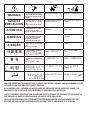
1
RETURN TO MAIN MENU
IM595-A
PRO-CUTTM 80
For use with machines having Code Numbers:
May, 2004
10573, 10574, 10575, 10576, 10577, 10578
11019, 11020, 11021, 11022, 11023, 11024
Safety Depends on You
Lincoln arc welding and cutting
equipment is designed and built
with safety in mind. However, your
overall safety can be increased by
proper installation ... and thoughtful operation on your part. DO
NOT INSTALL, OPERATE OR
REPAIR THIS EQUIPMENT
WITHOUT READING THIS
MANUAL AND THE SAFETY
PRECAUTIONS CONTAINED
THROUGHOUT. And, most
importantly, think before you act
and be careful.
OPERATOR’S MANUAL
Copyright © 2004 Lincoln Global Inc.
• World's Leader in Welding and Cutting Products •
• Sales and Service through Subsidiaries and Distributors Worldwide •
Cleveland, Ohio 44117-1199 U.S.A. TEL: 216.481.8100 FAX: 216.486.1751 WEB SITE: www.lincolnelectric.com
i
i
SAFETY
WARNING
PLASMA CUTTING or GOUGING can be hazardous.
PROTECT YOURSELF AND OTHERS FROM POSSIBLE SERIOUS INJURY OR DEATH. KEEP CHILDREN
AWAY. PACEMAKER WEARERS SHOULD CONSULT WITH THEIR DOCTOR BEFORE OPERATING.
Read and understand the following safety highlights. For additional safety information it is strongly recommended that you purchase a copy of “Safety in Welding & Cutting - ANSI Standard Z49.1” from the American Welding Society, P.O. Box 351040,
Miami, Florida 33135 or CSA Standard W117.2.
BE SURE THAT ALL INSTALLATION, OPERATION, MAINTENANCE, AND REPAIR PROCEDURES ARE
PERFORMED ONLY BY QUALIFIED INDIVIDUALS.
ELECTRIC SHOCK can
kill.
1.a. The electrode and work (or ground) circuits
are electrically “hot” when the power source is on.
Do not touch these “hot” parts with your bare skin
or wet clothing. Wear dry, hole-free gloves to
insulate hands.
1.b. When the power source is operating voltages in excess of
250 volts are produced. This creates the potential for serious
electrical shock - potentially even fatal.
1.c. Insulate yourself from work and ground using dry insulation.
When cutting or gouging in damp locations, on metal framework such as floors, gratings or scaffolds and when in positions such as sitting or lying, make certain the insulation is
large enough to cover your full area of physical contact with
work and ground.
1.d. Always be sure the work cable makes a good electrical connection with the metal being cut or gouged. The connection
should be as close as possible to the area being cut or
gouged.
1.e. Ground the work or metal to be cut or gouged to a good electrical (earth) ground.
1.f. Maintain the plasma torch, cable and work clamp in good,
safe operating condition. Replace damaged insulation.
FUMES AND GASES
can be dangerous.
3.a. Plasma cutting or gouging may produce
fumes and gases hazardous to health. Avoid
breathing these fumes and gases.When cutting
or gouging, keep your head out of the fumes.
Use enough ventilation and/or exhaust at the arc
to keep fumes and gases away from the breathing zone.
When cutting or gouging on lead or cadmium plated
steel and other metals or coatings which produce highly
toxic fumes keep exposure as low as possible and
below Threshold Limit Values (TLV) using local exhaust
or mechanical ventilation. In confined spaces or in some
circumstances, outdoors, a respirator may be required.
Additional precautions are also required when welding
on galvanized steel.
3.b. Do not use plasma arc cutting or gouging in locations near
chlorinated hydrocarbon vapors coming from degreasing,
cleaning or spraying operations. The heat and rays of the arc
can react with solvent vapors to form phosgene, a highly
toxic gas, and other irritating products.
3.c. Gases used for plasma cutting and gouging can displace air
and cause injury or death. Always use enough ventilation,
especially in confined areas, to insure breathing air is safe.
3.d. Read and understand the manufacturer’s instructions for this
equipment and the consumables to be used, including the
material safety data sheet (MSDS) and follow your employer’s safety practices.
1.g. Never dip the torch in water for cooling or plasma cut or
gouge in or under water.
1.h. When working above floor level, protect yourself from a fall
should you get a shock.
1.i. Operate the pilot arc with caution. The pilot arc is capable of
burning the operator, others or even piercing safety clothing.
1.j. Also see Items 4c and 6.
ARC RAYS can burn.
2.a. Use safety glasses and a shield with the proper filter and cover plates to protect your eyes from
sparks and the rays of the arc when performing or
observing plasma arc cutting or gouging.
Glasses,headshield and filter lens should conform
to ANSI Z87. I standards.
2.b. Use suitable clothing including gloves made from durable
flame-resistant material to protect your skin and that of your
helpers from the arc rays.
2.c. Protect other nearby personnel with suitable non-flammable
screening and/or warn them not to watch the arc nor expose
themselves to the arc rays or to hot spatter or metal.
CUTTING SPARKS can
cause fire or explosion.
4.a..Remove fire hazards from the plasma cutting or gouging area. If this is not possible, cover
them to prevent the cutting or gouging sparks
from starting a fire. Remember that welding
sparks and hot materials from plasma cutting or gouging can
easily go through small cracks and openings to adjacent
areas. Avoid cutting or gouging near hydraulic lines. Have a
fire extinguisher readily available.
4.b. Where compressed gases are to be used at the job site, special precautions should be used to prevent hazardous situations. Refer to “Safety in Welding and Cutting” (ANSI
Standard Z49.1) and the operating information for the equipment being used.
4.c. When not cutting or gouging, make certain no part of the electrode circuit is touching the work or ground. Accidental contact can cause overheating and create a fire hazard.
4.d. Do not cut or gouge tanks, drums or containers until the proper steps have been taken to insure that such procedures will
not cause flammable or toxic vapors from substances inside.
They can cause an explosion even though they have been
“cleaned.” For information purchase “Recommended Safe
Practices for the Preparation for Welding and Cutting of
Containers and Piping That Have Held Hazardous
Substances”, AWS F4.1 from the American Welding Society
(see address above).
4.e. Vent hollow castings or containers before heating, cutting or
gouging. They may explode.
4.f. Do nor fuel engine driven equipment near area where plasma
cutting or gouging.
Apr. ‘93
ii
ii
SAFETY
4.g. Sparks and spatter are thrown from the plasma arc. Wear
safety glasses, ear protection and oil free protective garments
such as leather gloves, heavy shirt, cuffless trousers, high
shoes and a cap over your hair. Wear ear plugs when cutting
or gouging out of position or in confined places. Always wear
safety glasses with side shields when in a cutting or gouging
area.
4.h. Connect the work cable to the work as close to the cutting or
gouging area as practical. Work cables connected to the building framework or other locations away from the cutting or
gouging area increase the possibility of the current passing
through lifting chains, crane cables or other alternate circuits.
This can create fire hazards or overheat lifting chains or
cables until they fail.
PLASMA ARC can injure.
7.a. Keep your body away from nozzle and
plasma arc.
7.b. Operate the pilot arc with caution. The pilot arc is capable of
burning the operator, others or even piercing safety clothing.
CYLINDER may explode
if damaged.
5.a. Use only compressed gas cylinders containing the correct gas for the process used and
properly operating regulators designed for the
gas and pressure used. All hoses, fittings, etc.
should be suitable for the application and maintained in good
condition.
5.b. Always keep cylinders in an upright position securely
chained to an undercarriage or fixed support.
5.c. Cylinders should be located:
• Away from areas where they may be struck or subjected to
physical damage.
• A safe distance from plasma cutting or gouging, arc welding operations and any other source of heat, sparks,
or flame.
5.d. Never allow any part of the electrode, torch or any other
electrically “hot” parts to touch a cylinder.
5.e. Keep your head and face away from the cylinder valve outlet
when opening the cylinder valve.
5.f. Valve protection caps should always be in place and hand
tight except when the cylinder is in use or connected for
use.
5.g. Read and follow the instructions on compressed gas cylinders, associated equipment, and CGA publication P-l,
“Precautions for Safe Handling of Compressed Gases in
Cylinders,”available from the Compressed Gas Association
1235 Jefferson Davis Highway, Arlington, VA 22202.
FOR ELECTRICALLY
powered equipment.
6.a. Turn off input power using the disconnect
switch at the fuse box before working on the
equipment.
ELECTRIC AND MAGNETIC FIELDS
may be dangerous
8.a. Electric current flowing through any conductor causes localized Electric and Magnetic
Fields (EMF). Cutting or gouging current creates EMF fields around torch cables and cutting
machines.
8.b. EMF fields may interfere with some pacemakers, so operators having a pacemaker should consult their physician
before cutting or gouging.
8.c. Exposure to EMF fields during cutting or gouging may have
other health effects which are now not known.
8d. All operators should use the following procedures in order to
minimize exposure to EMF fields from the cutting or gouging
circuit:
8.d.1. Route the torch and work cables together - Secure
them with tape when possible.
8.d.2. Never coil the torch cable around your body.
8.d.3. Do not place your body between the torch and
work cables. If the torch cable is on your right side,
the work cable should also be on your right side.
8.d.4. Connect the work cable to the workpiece as close as
possible to the area being cut or gouged.
8.d.5. Do not work next to cutting power source.
6.b. Install equipment in accordance with the U.S. National
Electrical Code, all local codes and the manufacturer’s recommendations.
6.c. Ground the equipment in accordance with the U.S. National
Electrical Code and the manufacturer’s recommendations.
Apr. ‘93
NOTES
iv
iv
SAFETY
PRÉCAUTIONS DE SÛRETÉ
Pour votre propre protection lire et observer toutes les instructions
et les précautions de sûreté specifiques qui parraissent dans ce
manuel aussi bien que les précautions de sûreté générales suivantes:
Sûreté Pour Soudage A L’Arc
1. Protegez-vous contre la secousse électrique:
a. Les circuits à l’électrode et à la piéce sont sous tension
quand la machine à souder est en marche. Eviter toujours
tout contact entre les parties sous tension et la peau nue
ou les vétements mouillés. Porter des gants secs et sans
trous pour isoler les mains.
b. Faire trés attention de bien s’isoler de la masse quand on
soude dans des endroits humides, ou sur un plancher
metallique ou des grilles metalliques, principalement dans
les positions assis ou couché pour lesquelles une grande
partie du corps peut être en contact avec la masse.
c. Maintenir le porte-électrode, la pince de masse, le câble
de soudage et la machine à souder en bon et sûr état
defonctionnement.
d.Ne jamais plonger le porte-électrode dans l’eau pour le
refroidir.
e. Ne jamais toucher simultanément les parties sous tension
des porte-électrodes connectés à deux machines à souder
parce que la tension entre les deux pinces peut être le
total de la tension à vide des deux machines.
f. Si on utilise la machine à souder comme une source de
courant pour soudage semi-automatique, ces precautions
pour le porte-électrode s’applicuent aussi au pistolet de
soudage.
2. Dans le cas de travail au dessus du niveau du sol, se protéger
contre les chutes dans le cas ou on recoit un choc. Ne jamais
enrouler le câble-électrode autour de n’importe quelle partie
du corps.
3. Un coup d’arc peut être plus sévère qu’un coup de soliel,
donc:
a. Utiliser un bon masque avec un verre filtrant approprié
ainsi qu’un verre blanc afin de se protéger les yeux du rayonnement de l’arc et des projections quand on soude ou
quand on regarde l’arc.
b. Porter des vêtements convenables afin de protéger la
peau de soudeur et des aides contre le rayonnement de
l‘arc.
c. Protéger l’autre personnel travaillant à proximité au
soudage à l’aide d’écrans appropriés et non-inflammables.
4. Des gouttes de laitier en fusion sont émises de l’arc de
soudage. Se protéger avec des vêtements de protection libres
de l’huile, tels que les gants en cuir, chemise épaisse, pantalons sans revers, et chaussures montantes.
zones où l’on pique le laitier.
6. Eloigner les matériaux inflammables ou les recouvrir afin de
prévenir tout risque d’incendie dû aux étincelles.
7. Quand on ne soude pas, poser la pince à une endroit isolé de
la masse. Un court-circuit accidental peut provoquer un
échauffement et un risque d’incendie.
8. S’assurer que la masse est connectée le plus prés possible
de la zone de travail qu’il est pratique de le faire. Si on place
la masse sur la charpente de la construction ou d’autres
endroits éloignés de la zone de travail, on augmente le risque
de voir passer le courant de soudage par les chaines de levage, câbles de grue, ou autres circuits. Cela peut provoquer
des risques d’incendie ou d’echauffement des chaines et des
câbles jusqu’à ce qu’ils se rompent.
9. Assurer une ventilation suffisante dans la zone de soudage.
Ceci est particuliérement important pour le soudage de tôles
galvanisées plombées, ou cadmiées ou tout autre métal qui
produit des fumeés toxiques.
10. Ne pas souder en présence de vapeurs de chlore provenant
d’opérations de dégraissage, nettoyage ou pistolage. La
chaleur ou les rayons de l’arc peuvent réagir avec les vapeurs
du solvant pour produire du phosgéne (gas fortement toxique)
ou autres produits irritants.
11. Pour obtenir de plus amples renseignements sur la sûreté,
voir le code “Code for safety in welding and cutting” CSA
Standard W 117.2-1974.
PRÉCAUTIONS DE SÛRETÉ POUR
LES MACHINES À SOUDER À
TRANSFORMATEUR ET À
REDRESSEUR
1. Relier à la terre le chassis du poste conformement au code de
l’électricité et aux recommendations du fabricant. Le dispositif
de montage ou la piece à souder doit être branché à une
bonne mise à la terre.
2. Autant que possible, I’installation et l’entretien du poste seront
effectués par un électricien qualifié.
3. Avant de faires des travaux à l’interieur de poste, la debrancher à l’interrupteur à la boite de fusibles.
4. Garder tous les couvercles et dispositifs de sûreté à leur
place.
5. Toujours porter des lunettes de sécurité dans la zone de
soudage. Utiliser des lunettes avec écrans lateraux dans les
Mar. ‘93
v
v
Thank You
for selecting a QUALITY product by Lincoln Electric. We want you
to take pride in operating this Lincoln Electric Company product
••• as much pride as we have in bringing this product to you!
Please Examine Carton and Equipment For Damage Immediately
When this equipment is shipped, title passes to the purchaser upon receipt by the carrier. Consequently, Claims
for material damaged in shipment must be made by the purchaser against the transportation company at the
time the shipment is received.
Please record your equipment identification information below for future reference. This information can be
found on your machine nameplate.
Product _________________________________________________________________________________
Model Number ___________________________________________________________________________
Code Number or Date Code_________________________________________________________________
Serial Number____________________________________________________________________________
Date Purchased___________________________________________________________________________
Where Purchased_________________________________________________________________________
Whenever you request replacement parts or information on this equipment, always supply the information you
have recorded above. The code number is especially important when identifying the correct replacement parts.
On-Line Product Registration
- Register your machine with Lincoln Electric either via fax or over the Internet.
• For faxing: Complete the form on the back of the warranty statement included in the literature packet
accompanying this machine and fax the form per the instructions printed on it.
• For On-Line Registration: Go to our WEB SITE at www.lincolnelectric.com. Choose “Quick Links” and then
“Product Registration”. Please complete the form and submit your registration.
Read this Operators Manual completely before attempting to use this equipment. Save this manual and keep it
handy for quick reference. Pay particular attention to the safety instructions we have provided for your protection.
The level of seriousness to be applied to each is explained below:
WARNING
This statement appears where the information must be followed exactly to avoid serious personal injury or
loss of life.
CAUTION
This statement appears where the information must be followed to avoid minor personal injury or damage to
this equipment.
vi
vi
TABLE OF CONTENTS
Page
Installation.......................................................................................................................Section A
Technical Specifications .......................................................................................................A-1
Safety Precautions ...............................................................................................................A-2
Select Proper Location .........................................................................................................A-2
Stacking................................................................................................................................A-2
Lifting and Moving ................................................................................................................A-2
Tilting ....................................................................................................................................A-2
High Frequency Interference Protection...............................................................................A-2
Input Electrical Connections .................................................................................................A-3
Power Input Connection for 208/230/460 Volt Machines .....................................................A-3
Power Input Connection for 200/380-415 Volt Machines .....................................................A-3
Input Power Cord Connector Installation..............................................................................A-3
Cord Removal ...............................................................................................................A-3
Cord Installation ............................................................................................................A-3
Frame Grounding .................................................................................................................A-4
Input Voltage Reconnection Procedure................................................................................A-4
Use on Engine Driven Power Supplies ................................................................................A-4
Gas Input Connections .........................................................................................................A-5
Output Connections..............................................................................................................A-5
Torch Connection ..........................................................................................................A-5
Operation.........................................................................................................................Section B
Safety Precautions ...............................................................................................................B-1
Description ...........................................................................................................................B-1
Preheat Temperature for Plasma Cutting.............................................................................B-1
User Responsibility...............................................................................................................B-2
Recommended Processes and Equipment ..........................................................................B-2
Operational Features and Controls ......................................................................................B-2
Design Features and Advantages ........................................................................................B-2
Cutting Capability .................................................................................................................B-3
Consumable Life ..................................................................................................................B-3
Limitations ............................................................................................................................B-4
Controls and Settings ...........................................................................................................B-4
Gas Pressure Settings .........................................................................................................B-4
Preparing to Cut ...................................................................................................................B-4
Safety LED ...........................................................................................................................B-5
Pilot Arc Discussion..............................................................................................................B-6
Procedure Recommendations ..............................................................................................B-6
General .........................................................................................................................B-6
Thin Gauge Sheet Metal ...............................................................................................B-6
Thick Sections of Metal .................................................................................................B-6
Suggestions for Extra Utility from the PRO-CUT System .............................................B-7
Machine Interface .................................................................................................................B-7
Accessories .....................................................................................................Section C
Genuine Lincoln Parts ...........................................................................................C-1
General Options / Accessories ..............................................................................C-1
vii
vii
TABLE OF CONTENTS
Page
Maintenance ....................................................................................................Section D
Safety Precautions ................................................................................................D-1
Input Filter Capacitor Discharge Procedure ..........................................................D-1
Routine Maintenance.............................................................................................D-2
Periodic Maintenance ............................................................................................D-2
Troubleshooting ..............................................................................................Section E
Safety Precautions.................................................................................................E-1
How to Use Troubleshooting Guide.......................................................................E-1
Troubleshooting Guide.............................................................................E-2 thru E-7
Wiring Diagrams ..............................................................................................Section F
Wiring Diagrams.......................................................................................F-1 thru F-4
Dimension Print......................................................................................................F-5
Parts List ........................................................................................P340, P210-K Series
A-1
A-1
INSTALLATION
TECHNICAL SPECIFICATIONS - PRO-CUT 80
INPUT
THREE PHASE
Standard
Voltage
208/230/460
200/380-415
460/575
SINGLE PHASE
Input Current
at Rated Output
48/44/25
46/27/24
25/20
Standard
Voltage
208/230/460
Model
50/60 Hz
50/60 Hz
50/60 Hz
Input Current
at Rated Output
87/81/48
Model
50/60Hz
RATED OUTPUT
Duty Cycle
AMPS
VOLTS
60% Duty Cycle
100% Duty Cycle
80
60
140
130
OUTPUT
Current
Range
Open Circuit
Voltage
Pilot Current
MAX
335 VDC
20 Amps @ 100% Duty Cycle
35-85 Amps
REQUIRED GAS FLOW RATE
REQUIRED GAS INLET PRESSURE
70 PSI @ 480 SCFH
( 4.8 Bar. @ 13550 LHR)
80 to 120 PSI
( 5.4 Bar. to 8.1 Bar.)
RECOMMEND INPUT WIRE AND FUSE SIZES
For all plasma cutting applications Based on U.S. National Electrical Code
Ambient Temperature 30oC or Less
RECOMMENDED INPUT WIRE AND FUSE SIZES
THREE PHASE
SINGLE PHASE
Input
Voltage
Frequency(1)
Fuse
(Superlag)
or
Breaker
Size
Type 75°C
Copper
Wire in
Conduit
AWG (IEC)
Sizes
60
60
60
40
40
8 (8.4mm2)
8 (8.4mm2)
8 (8.4mm2)
10 (6mm2)
10 (6mm2)
30
10 (6mm )
200/50/60
208/50/60
230/50/60
380-415/50/60
460/50/60
575/50/60
Type 75°C
Copper
Ground
Wire in
Conduit
AWG (IEC)
Sizes
8 (8.4mm2)
8 (8.4mm2)
8 (8.4mm2)
10 (6mm2)
Input
Voltage
Frequency(1)
Fuse
(Superlag)
or
Breaker
Size
Type 75°C
Copper
Wire in
Conduit
AWG (IEC)
Sizes
Type 75°C
Copper
Ground
Wire in
Conduit
AWG (IEC)
Sizes
208/50/60
230/50/60
460/50/60
100
100
60
4 (21.1mm2)
4 (21.1mm2)
8 (8.4mm2)
4 (21.1mm2)
4 (21.1mm2)
8 (8.4mm2)
10 (6mm2)
10 (6mm2)
2
PHYSICAL DIMENSIONS
Height
Width
Depth
16.5 in.
419 mm
13.75 in.
349 mm
29.5 in.
749 mm
(1) Input voltage must be within ±10% of rated value.
Weight
Including Machine, Torch and
Torch Cable (Length)
(25ft/7.6m) (50ft/15.2m)
98 lbs.
113 lbs.
44.5 kg.
51.4 kg.
A-2
INSTALLATION
Read entire Installation Section before installing the
PRO-CUT 80.
A-2
LIFTING AND MOVING
Either the front or rear handles or both may be used to
lift or move the machine.
SAFETY PRECAUTIONS
WARNING
ELECTRIC SHOCK CAN KILL.
•
•
Only qualified personnel
should install this machine.
Turn the input power OFF
at the disconnect switch or
fuse box and discharge input
capacitors before working
inside the equipment.
•
Do not touch electrically hot parts.
•
Always connect the PRO-CUT 80 grounding terminal (located on the side of the
Case Back Assembly) to a good electrical
earth ground.
•
Turn the PRO-CUT Power Switch OFF
when connecting power cord to input
power.
___________________________________________
SELECT PROPER LOCATION
Place the PRO-CUT 80 where clean cool air can
freely circulate in through the rear louvers and out
through the side/bottom openings. Dirt, dust or any
foreign material that can be drawn into the machine
should be kept at a minimum. Failure to observe these
precautions can result in excessive operating temperatures and nuisance shutdown of the machine.
A source of clean, dry air or nitrogen must be supplied
to the PRO-CUT 80. Oil in the air is a severe problem
and must be avoided. The supply pressure must be
between 80 and 120 psi. The flow rate is approximately 8.0 cfm (227 l/min.). Failure to observe these precautions could result in excessive operating temperatures or damage to the torch.
STACKING
DO NOT use the pull handle on the optional undercarriage, if installed, to lift the machine. This handle is not
designed to support the full weight of the machine and
using it to lift the machine could cause personal injury
or damage to the machine.
TILTING
The PRO-CUT 80 must be placed on a stable, level
surface so it will not topple over.
HIGH FREQUENCY INTERFERENCE
PROTECTION
The PRO-CUT 80 employs a touch start mechanism
for arc initiation which eliminates high frequency emissions from the machine as compared with spark gap
and solid state type high frequency generators. Keep
in mind, though, that these machines may be used in
an environment where other high frequency generating machines are operating. By taking the following
steps, high frequency interference into the Pro-Cut
can be minimized
(1) Make sure the power supply chassis is connected
to a good earth ground. The work terminal ground
does NOT ground the machine frame.
(2) Keep the work ground clamp isolated from other
work clamps that have high frequency.
(3) If the ground clamp cannot be isolated, then keep
the clamp as far as possible from other work
clamp connections.
(4) When the machine is enclosed in a metal building,
several good earth driven electrical grounds
around the periphery of the building are recommended.
Failure to observe these recommended installation
procedures may cause improper function of the ProCut or possibly even damage to the control system or
power supply components.
The PRO-CUT 80 cannot be stacked.
PRO-CUT 80
A-3
A-3
INSTALLATION
CORD REMOVAL:
INPUT ELECTRICAL
CONNECTIONS
1. Unplug line cord from the receptacle.
Before installing the machine, check that input supply
voltage, phase, and frequency are the same as the
machine's voltage, phase, and frequency as specified
on the machine's rating plate.
The Pro-Cut 80 should be connected only by a qualified electrician. Installation should be made in accordance with all local and national codes (eg: U.S.
National Electrical Code) and the information detailed
below.
THREE PHASE POWER INPUT CONNECTION FOR THE PRO-CUT 80
The Pro-Cut 80’s are supplied with one 10 ft. #8 AWG
4-conductor input power cord already connected to
the machine. When received from the factory, the
machine is internally connected for the higher input
voltage. Re-connection will be necessary if a lower
input voltage is used.
CONVERTING THE PRO-CUT 80 FROM
THREE PHASE TO SINGLE PHASE INPUT
To convert to single phase power, the 4-conductor
input cord may still be used, but the red lead must be
disconnected and insulated.
1. Connect the green lead to ground per U.S. National
Electrical Code.
2. Connect black and white leads to power.
3. Wrap red lead with tape to provide 600V insulation.
WARNING
Machine damage could result if the machine is
improperly configured for the Input Voltage
applied.
------------------------------------------------------------------------
INPUT POWER CORD CONNECTOR
INSTALLATION
A cord connector provides a strain relief for the input
power cord as it passes through the left rear access
hole. The cord connector is designed for a cord diameter of .40 - 1.03 in (10.2 - 26.2mm) if it becomes necessary to install a different input cord.
WARNING
NOTE: DO NOT PERFORM THE NEXT STEP
UNTIL THE HIGH VOLTAGES INSIDE THE
MACHINE HAVE BEEN ALLOWED TO DISSIPATE,
APPROXIMATELY TWO MINUTES.
-----------------------------------------------------------------------2. Remove wraparound by unscrewing the eleven
screws on the case sides and top.
3. Unscrew the four screws that hold the line switch
onto the case front.
4. Pull the line switch out of the case front.
5. Angle the line switch so the nuts on the switch can
be loosened.
6. Remove the cord from the switch.
7. Remove the nut, lock washer, plain washer and
green lead off of the ground screw assembly.
8. Loosen the cable connector on the case back.
9. Pull the line cord out of the machine.
CORD INSTALLATION:
1. Feed the new cord through the cable connector
and into the machine.
2. If the ground screw assembly is loose, tighten the
assembly to the base before installing the new
ground lead. Install the green lead on the ground
screw assembly, replace the plain washer and lock
washer, then tighten nut. Install in accordance with
all local and national electrical codes.
3. Connect the new cord to the switch, observing the
color code on the wiring diagram.
4. Feed the line switch back into case front.
5. Replace the four screws that hold the line switch
onto the case front.
6. Tighten the cable connector on the case back.
7. Replace wraparound and tighten the eleven
screws on the case sides and top.
8. Connect the new input power cord to a fused three
phase power supply. Make sure the green lead is
connected to the panel and the panel is connected
to a good earth ground. Install in accordance with
all local and national electric codes.
NOTE: Fusing requirements of the machine input will
change, depending on whether the machine is used
on single phase or three phase. Use the chart in the
TECHNICAL SPECIFICATIONS to change the fuses
to the proper value.
PRO-CUT 80
A-4
A-4
INSTALLATION
For 380 - 415 VAC Supplies:
FRAME GROUNDING
The frame of the Pro-Cut 80 must be properly grounded. A ground terminal marked
is mounted on the
case bottom directly behind the input power switch for
this purpose. The cable that is sent attached to the
machine is connected to this ground terminal. See the
National Electric Code for details on proper grounding
methods. Install in accordance with all local and
national electrical codes.
The AC wave form peak voltage must be below 840
volts.
The RMS voltage must be 400 VAC +/- 10%.
For 460 VAC Supplies:
RECONNECTION
The AC wave form peak voltage must be below 840
volts.
The RMS voltage of the AC wave form must be 460
VAC +/- 10%.
When changing input voltages, it is necessary to
change the settings behind the access door on the
side of the machine. Failure to do so may result in
damage to the machine.
Input Power Restrictions
The available output current of the Pro-Cut 80 may be
limited due to the output capacity of the engine driven
power supply. The following are recommended output
current settings when used with various Lincoln
engine driven power supplies.
INPUT VOLTAGE
PROCEDURE
To reconnect the Pro-Cut, follow the directions as outlined below. Follow this procedure ONLY while the
Pro-Cut is disconnected from the input power and the
capacitors have properly discharged.
1. Open the access door on the back of the machine.
2. For 200 to 230 : Position the large switch to 200-230.
For 400 to 460 : Position the large switch to 400-460.
For 550 to 575 : Position the large switch to 550-575.
3. Move the "A" lead to the appropriate terminal.
Engine Drive
RANGER 8
RANGER 9
GX271
RANGER 275
RANGER 250
RANGER 300D
RANGER 305G
RANGER 305D
COMMANDER 300
COMMANDER 400
COMMANDER 500
VANTAGE 500
USE ON ENGINE DRIVEN POWER SUPPLIES
The Pro-Cut 80 can be used on engine driven power
supplies. However, the following AC Wave Form
Voltage and Input Power Restrictions do apply.
AC Wave Form Restrictions
The Pro-Cut 80 can be operated on engine driven
generators as long as the engine drive output meets
the following conditions:
The AC wave form frequency is between 45 and 65
Hz.
For 200 - 230 VAC Supplies:
The AC wave form peak voltage must be below 420
volts.
The RMS voltage must be 230VAC +/- 15%.
* The 230 VAC auxiliaries of Lincoln engine drives
meet these conditions when run in the high idle
mode.
PRO-CUT 80
Auxiliary Power
Pro-Cut 80 Output
Cut Thickness
8KW
9KW
8KW
9KW
8.5KW
12KW
9.5KW
9.5KW
10KW
10K
12KW
12KW
30 Amps
40 Amps
30 Amps
40 Amps
35 Amps
55 Amps
40 Amps
40 Amps
45 Amps
45 Amps
55 Amps
55 Amps
5/16”
3/8”
5/16”
3/8”
5/16”
5/8”
3/8”
3/8”
1/2”
1/2”
5/8”
5/8”
A-5
A-5
INSTALLATION
GAS INPUT CONNECTIONS
Supply the PRO-CUT 80 with clean compressed air or
nitrogen.
• Supply pressure must be between 80 psi(5.6kg/cm2)
and 120 psi(8.4kg/cm2).
• Pressure gage, located on the front of the machine,
should be set to approximately 70 psi(4.9kg/cm2) for
a 25ft.(7.6m) torch and 75 psi(5.3kg/cm2) for a 50
ft.(15.2m) torch while gas is flowing (purging or cutting).
• Flow rate should be approximately 8.0 cfm (227
I/min.).
NOTE: Oil in the air supply to the PRO-CUT 80 can
cause severe problems. Use only a clean air
supply.
• Connect the gas supply to the PRO-CUT 80 regulator.
• While it is recommended that an in line prefilter be
placed ahead of each PRO-CUT that may be
installed in a shared air supply line, one large inline
prefilter may instead be used to accommodate several PRO-CUTs simultaneously. If a shared prefilter
is desired, it must be rated to provide the necessary
flow rate, as specified, to ensure proper operation of
each of the PRO-CUTs sharing a connection.
NOTE: When using nitrogen gas from a cylinder, the
cylinder must have a pressure regulator.
• Maximum psi from nitrogen gas cylinder to PROCUT 80 regulator should never exceed 120
psi(8.4kg/cm2).
• Install a hose between the nitrogen gas cylinder regulator and the PRO-CUT 80 gas inlet.
WARNING
• Compressed gas should be supplied to the fitting
connection mounted on the filter at the rear of the
machine. If necessary, this fitting can be removed
allowing plumbing access through the 1/4” NPT input
port on the filter body.
• If compressed air is being used, it is highly recommended that an inline prefilter be installed in the air
supply line ahead of the air connection to the PROCUT’s coalescing filter. While the coalescing filter is
used to remove small amounts of oil and water
aerosol particles from the air supply line, the prefilter
can be used to remove larger particulates before
they reach the coalescing filter element. This will
prolong the life of the coalescing filter element by up
to six times what it would be without the prefilter, and
in turn, prolong the life of the PRO-CUT torch and
consumables as well.
• A standard nominal 5 micron inline prefilter is recommended; however, for optimum performance, select
a prefilter with a 3 micron absolute rating. If these filter ratings are unavailable, anything with a rating
less than, or equal to, 20 micron would be acceptable to use. In line filter elements will generally filter
the air with little restriction to the airflow until the element is about 75 % contaminated. After this point,
there will be a noticeable pressure drop in the line.
Filter elements should be replaced when a pressure
drop of 8-10psi(.56-.70kg/cm2) is indicated; however,
for optimum performance of the PRO-CUT, the filter
element should be replaced at or before the pressure drop reaches 8 psi(.56kg/cm 2 ). Be sure to
select a prefilter that will accommodate the necessary flow rating for the PRO-CUT as specified in the
Installation section of this instruction manual under
the Gas Input Connections heading.
• CYLINDER could explode if
damaged.
• Keep cylinder upright and
chained to a fixed support.
• Keep cylinder away from areas
where it could be damaged.
• Never lift machine with cylinder
attached.
• Never allow the cutting torch to touch the cylinder.
• Keep cylinder away from live electrical parts.
• Maximum inlet pressure 120 psi(8.4kg/cm2).
__________________
OUTPUT CONNECTIONS
Torch Connection
The Pro-Cut 80 is sent from the factory with a PCT 80
cutting torch. Additional cutting torches can be
ordered from the K1571 series. Hand-held and mechanized torches come with 25'(7.6m) or 50’(15.2m)
cables.
All torches are connected to the Pro-Cut with a quick
connect on the case front for easy change over. This
feature is excellent for changing between a hand cutting torch and a mechanized torch.
For more information on the torch and its components,
refer to the PCT80 Operator’s Manual (IM588 latest
version).
PRO-CUT 80
B-1
OPERATION
Read and understand this entire section before operating the machine.
SAFETY PRECAUTIONS
WARNING
ELECTRIC SHOCK
can kill.
• Do not touch electrically live parts
or electrode with skin or wet
clothing.
• Insulate yourself from work and
ground.
B-1
DESCRIPTION
The PRO-CUT 80 is a constant current, continuous control plasma cutting power source. It provides superior
and reliable starting characteristics, cutting visibility and
arc stability. When cutting expanded metal, the PROCUT 80 out performs the competition due to its quick,
clean response to arc transfers. The power supply
design provides high transfer-to-cut distances which
makes pierce cutting more reliable and with less nozzle
wear. The control system has a safety mechanism to
insure that the nozzle and electrode are in place before
cutting or gouging. This is extremely important due to the
high voltages involved.
The PRO-CUT 80 comes standard with an air regulator,
coarse air filter, and pressure gauge. There are six different torch and cable systems to choose from: hand-held
torch with 25'(7.6m) or 50'(15.2) cable, machine and
robotic torch both with 25'(7.6m) and 50'(15.2) cable.
Consumables are included so that cutting can begin right
out of the box. Consumables can also be ordered as individual packages.
• Always wear dry insulating
gloves.
FUMES AND GASES
can be dangerous.
• Keep your head out of fumes.
The PRO-CUT 80 initiates the plasma arc with a simple,
yet reliable, touch start mechanism. This system eliminates many of the failure problems associated with hi-frequency start systems. The PRO-CUT 80 is capable of
cutting with nitrogen or air.
• Use ventilation or exhaust to
remove fumes from breathing
zone.
WELDING, CUTTING and
GOUGING SPARKS
can cause fire or explosion
• Keep flammable material away.
• Do not weld, cut or gouge on
containers that have held combustibles.
ARC RAYS
can burn.
• Wear eye, ear and body
protection.
The PRO-CUT 80 is controlled by a microprocessorbased control board. The machine performs rudimentary
self troubleshooting when powered up which aids in field
servicing.
NOTE: All P.C. boards are protected by a moisture resistant coating. When the plasma cutter is operated, this
coating will "bake off" of certain power resistors that normally operate at high temperatures emitting some smoke
and odor for a short time. These resistors and the P.C.
board beneath them may become darkened. This is a
normal occurrence and does not damage the component
or affect the machine performance.
PREHEAT TEMPERATURE FOR
PLASMA CUTTING
PLASMA ARC
can injure
• Keep your body away from nozzle
and plasma arc.
• Operate the pilot arc with caution. The
pilot arc is capable of burning the
operator, others or even piercing
safety clothing.
Observe additional Safety Guidelines detailed in
the beginning of this manual.
Preheat temperature control is not necessary in most
applications when plasma arc cutting or gouging. Preheat
temperature control may be necessary on high carbon
alloy steels and heat treated aluminum for crack resistance and hardness control. Job conditions, prevailing
codes, alloy level, and other considerations may also
require preheat temperature control. The following minimum preheat temperature is recommended as a starting
point. Higher temperatures may be used as required by
the job conditions and/or prevailing codes. If cracking or
excessive hardness occurs on the cut face, higher preheat
temperature may be required. The recommended minimum preheat temperature for plate thickness up to 1/2"
(12.7mm) is 70°F (21.1°C).
PRO-CUT 80
B-2
OPERATION
USER RESPONSIBILITY
- Input over voltage protection.
Because design, fabrication, erection and cutting variables affect the results obtained in applying this type
of information, the serviceability of a product or structure is the responsibility of the user. Variation such as
plate chemistry, plate surface condition (oil, scale),
plate thickness, preheat, quench, gas type, gas flow
rate and equipment may produce results different than
those expected. Some adjustments to procedures
may be necessary to compensate for unique individual conditions. Test all procedures duplicating actual
field conditions.
- Bright 3.0 second timed pilot arc.
RECOMMENDED PROCESSES AND
EQUIPMENT
B-2
- Purge momentary push button.
- Air regulator and pressure gage located on the front
of machine for convenience.
- Parts-in-Place mechanism to detect proper installation of consumables and torch.
- Latching Parts-in-Place mechanism. Requires a
positive operator reset.
- Automatic detection of faulty output control.
- In line coarse air filter.
The PRO-CUT 80 is capable of all cutting and gouging applications within its output capacity of 35 to 85
amps. These applications include thin gage sheet
metal and expanded metal.
- Preflow/Postflow timing. Preflow is eliminated if arc
is re-initiated in Postflow.
- Thermostatic Protection.
OPERATIONAL FEATURES AND
CONTROLS
- Solid state over-current protection.
The PRO-CUT 80 comes with an ON/OFF POWER
SWITCH, OUTPUT CURRENT CONTROL, PURGE
BUTTON and a SAFETY RESET BUTTON.
- Works with pure nitrogen for cutting nonferrous
materials.
- Reconnectable for multiple input voltages.
DESIGN FEATURES AND
ADVANTAGES
- Quick disconnect torch.
The microprocessor controlled PRO-CUT 80 design
makes plasma cutting and gouging tasks uncomplicated. This list of design features and advantages will
help you understand the machine's total capabilities
so that you can get maximum use from your machine.
- Unique electrode and Vortech™ nozzle design for
optimum cooling and long life.
- Portable design for industrial use.
- Unique drag cup design for durability and elimination of double arcing.
- Dead front display for machine status.
- Swirl texture inside Vortech™ nozzle for better starting reliability and higher quality cuts.
- Continuous output control, 35 - 85 amps.
- Reliable touch start mechanism for plasma arc initiation.
- Unique microprocessor controlled starting sequence
for safe and consistent starting.
- Rapid arc transfer for fast cutting of expanded
metal.
- High transfer distance for ease of use.
- Soft start of input filter capacitors at start up.
PRO-CUT 80
B-3
B-3
OPERATION
CUTTING CAPABILITY
The PRO-CUT 80 is rated at 80 amps, at 60% duty cycle on a 10 minute basis (runs 80 amps for 6 minutes, then
idling for 4 minutes) or 60 amps, at 100% duty cycle (continuous use). If the duty cycle is exceeded, a thermal
protector will shut off the output of the machine until it cools to the normal operating temperature.
Recommended Torch Travel Speed (IPM)(mm/m)
80% of Maximum Speed
Figure B.1 shows the cut capacity of the PRO-CUT 80 when cutting mild steel. The graph plots cut thickness vs.
torch travel speed with a torch standoff of 0.15"(3.8mm). Example: 0.5”(12.7mm) material may be cut at a setting
of 55 amps at an approximate speed of 25”/m(635mm/m) or at a setting of 80 amps at an approximate speed of
35”/m(889mm/m).
Lincoln’s PRO-CUT 80
Mild Steel Cut Capacity Chart
100
2540
80
2032
60
1524
40
1016
20
508
0
0.000
25 A
0.125
(3.2mm)
0.250
(6.4mm)
35 A
0.375
(9.5mm)
0.500
(12.7mm)
55 A
80 A
0.625
0.750
1.00
(15.9mm) (19.1mm) (25.4mm)
Figure B.1
CONSUMABLE LIFE
The expected life for the PRO-CUT 80’s electrode under normal conditions is approximately 30 to 40 minutes of
cutting time at the machine’s maximum rated output. An erosion of approximately 1/16" in the electrode tip is typical for the end of electrode life, however, the electrode may last longer. A sustained green and erratic arc will
indicate definite electrode failure and both the electrode and nozzle should be replaced immediately.
It is recommended that consumables (electrode and nozzle) be replaced in complete sets. This will maximize the
performance of the PRO-CUT system.
PRO-CUT 80
B-4
B-4
OPERATION
LIMITATIONS
Do not exceed the output current and duty cycle rating
of machine. Do not use the PRO-CUT 80 for pipe
thawing.
GAS PRESSURE SETTINGS
CONTROLS AND SETTINGS
Status
Indicators
Reset
Button
XXXX
XXXX
XXXX
Gas
Purge
Button
Gas
Regulator
Gauge
XXXX
Gas
Regulator
Knob
Output
Control
Knob
• Push-in and hold the Purge button to check or set
the gas pressure. Pull the pressure regulator cap
out and turn it to set the pressure.
- Adjust the gas regulator for 70psi(4.9kg/cm2) for
25’(7.6m) torches or 75psi(5.3kg/cm 2 ) for
50’(15.2m torches.
- Release the Purge button.
- The gas will immediately turn off. The pressure
gage may show an increase in pressure after the
air turns off but this is normal. Do NOT reset the
pressure while the air is NOT flowing.
PRO-CUT 80
Consumable
Storage
(behind
door)
Torch
Connector
• Set the output current control knob at maximum
position for high cutting speed and less dross formation. Reduce the current, if desired to reduce the
kerf (cut) width, heat affected zone or travel speed
as required.
PREPARE TO CUT
Input
Power
Switch
Work
Cable
Interface
Connector
When preparing to cut or gouge, position the machine
as close to the work as possible. Make sure you have
all materials needed to complete the job and have
taken all safety precautions. It is important to follow
these operating steps each time you use the machine.
• Turn the machine's ON/OFF POWER SWITCH to
OFF position.
• Connect the air supply to the machine.
• Turn the main power and the machine power switch
on.
- The fan should start.
- The pre-charge circuit will operate with all the
LED’s lit and steady for 4 seconds, then all the
LED’s should turn off except for the green
"POWER" LED.
- If the "SAFETY" LED is lit and steady, push the
"RESET" button. If there is no problem, the LED
will go off. If there is a problem, refer to the heading "SAFETY LED" in this section.
- If any of the other LED’s remain lit and steady,
refer to the troubleshooting section of the manual.
• When ready to cut, place the torch near the work,
make certain all safety precautions have been taken
and pull the trigger.
- The air will flow for a preflow time of 2 seconds
and the pilot arc will start. (This is true unless
the machine is in postflow, then the preflow time
is skipped and the pilot arc will start immediately.)
- The pilot arc will run for 3.0 seconds and shut off
unless the arc is brought in contact with the work
and the arc is transferred. Avoid excessive pilot
arc time by transferring the arc to the workpiece
quickly to improve parts life.
- When the arc is brought within 1/4"(6.4mm) from
the work piece: the arc will transfer, the current
will ramp up to the setting on the control panel,
and the cut can last indefinitely (or until the duty
cycle of the Pro-Cut is exceeded). Do not touch
the nozzle to the work when cutting with the
control panel setting above 45 Amps or damage
to the consumables will result.
• Pierce the work piece by slowly lowering the torch
onto the metal at a 300 angle away from the operator. This will blow the dross away from the torch tip.
Slowly rotate the torch to vertical position as the arc
becomes deeper.
TORCH AT 300 ANGLE
TO PIERCE
ROTATE TO
0
90 ANGLE TO CUT
300
Gloves required
90
• Be sure that the work lead is clamped to the workpiece before cutting.
PRO-CUT 80
0
CUT
VERTICAL ANGLE
VERTICAL
FOR CUTTING
B-5
B-5
OPERATION
ANGLE
OF APPROACH
• Hold the nozzle standoff 1/8” (3.2mm) to 3/16”
(4.8mm) above the workpiece during cutting. Do not
let the nozzle touch the work or carry a long arc.
Gloves Required
TORCH HELD AT
0
45 ANGLE
THROUGHOUT GOUGE
• Keep moving while cutting. Cut at a steady speed
without pausing. Maintain the cutting speed so that
the arc leg is 10° to 20° behind the travel direction.
5° - 15°
ANGLE
MAINTAINED
THROUGHOUT
GOUGE
Leading Angle
SAFETY LED
• If the "SAFETY" LED lights at any time, check the
following:
WARNING
ELECTRIC SHOCK CAN KILL.
• Turn off machine at the disconnect
switch on the front of the machine
before tightening, cleaning or replacing
consumables.
----------------------------------------------------------------------------
Direction of Travel
10° - 20° Arc Lag
• Use a 5° - 15° leading angle in the direction of the
cut.
• Use the drag cup to maintain constant standoff for
better cut quality and to protect the nozzle from spatter.
• Use the drag cup with a metal template to prevent
nozzle double arcing.
• Finish the cut and release the trigger.
• When the trigger is released, the arc will stop.
- The gas will continue to flow for 10 seconds of
postflow. If the trigger is activated within this time
period, the pilot arc will immediately restart.
• In normal operation, the "SAFETY" LED may temporarily illuminate and clear itself automatically without depressing the reset button.
• Check the assembly of the torch consumables. If
they are not properly in place, the machine will not
start. Make sure that the shield cup is hand tight.
Do not use pliers or over tighten.
• Check the conditions of the inside of the nozzle. If
debris has collected, rub the electrode on the inside
bottom of the nozzle to remove any oxide layer that
may have built up. Refer to "Suggestions for Extra
Utility from the PRO-CUT system".
• If the dross is difficult to remove, reduce the cutting
speed. High speed dross is more difficult to remove
than low speed dross.
• Check the condition of the electrode. If the end has
a crater-like appearance, replace it along with the
nozzle. The maximum wear depth of the electrode is
approximately 1/16”. A green and erratic arc will
indicate definite electrode failure and the electrode
should be replaced immediately.
• The right side of the cut is more square than the left
as viewed along the direction of travel.
• Replace the nozzle when the orifice exit is eroded
away or oval shaped.
• Tilt the torch about 45° from the workpiece and hold
the nozzle 1/8” (3.2mm) to 3/16” (4.8mm) above the
workpiece for gouging.
• After the problem is found, or if there is nothing
apparently wrong, reset the machine by pressing
the "Reset" button. (It is possible for electrical noise
to trip the safety circuit on rare occasions. This
should not be a regular occurrence.)
• Clean spatter and scale from the nozzle and drag
cup frequently.
• If the machine does not reset or continues to trip,
consult the Troubleshooting Section.
• Use the proper cutting or gouging procedures
referred to in Procedure Recommendations.
PRO-CUT 80
B-6
B-6
OPERATION
Thick Sections of Metal
PILOT ARC DISCUSSION
The PRO-CUT has a smooth, continuous pilot arc.
The pilot arc is only a means of transferring the arc to
the workpiece for cutting. Repeated pilot arc starts, in
rapid succession, is not recommended as these starts
will generally reduce consumable life. Occasionally,
the pilot arc may sputter or start intermittently. This is
aggravated when the consumables are worn or the air
pressure is too high. Always keep in mind that the
pilot arc is designed to transfer the arc to the workpiece and not for numerous starts without cutting.
When the pilot arc is started, a slight impulse will be
felt in the torch handle. This occurrence is normal and
is the mechanism which starts the plasma arc. This
impulse can also be used to help troubleshoot a "no
start" condition.
Torch Standoff
45
1/8"(3.2mm) thru
3/16"(4.8mm)Standoff
Output Setting
Mid. thru Max. Range
Output set above 45 Amps.
PROCEDURE RECOMMENDATIONS
When properly used, plasma arc cutting or gouging is
a very economical process. Improper use will result in
a very high operating cost.
General - In All Cases
• Follow safety precautions as printed throughout
this operating manual and on the machine.
Thin Gauge Sheet Metal:
Torch Standoff
Machine Output Setting
Machine Output Setting
• The best quality and consumable life will be
obtained by holding the torch off the surface
about 3/16"(4.8mm). Too long an arc may compromise cut quality and consumable life. When
the output setting is above mid-range, the nozzle should NOT be dragged on the work.
Failure to do so will result in shortened consumable life.
• Use of the S22151 Drag Cup will maintain the
proper standoff and eliminate nozzle double
arcing.
• If piercing is required, slowly lower the torch at
an angle of about 30° to blow the dross away
from the torch tip and slowly rotate the torch to
a vertical position as the arc becomes deeper.
This process will blow a lot of molten metal and
dross. Be careful! Blow the dross away from
the torch, the operator and any flammable
objects.
• Where possible, start the cut from the edge of
the work piece.
45
• Keep moving! A steady speed is necessary.
Do not pause.
DRAG thru 1/16"(1.6mm)
Standoff
Output Setting
Min. thru Mid. Range
Output set below 45 Amps.
• The nozzle may be dragged on the metal surface, touching it lightly to the surface after piercing a hole. Current control should be set
below the mid range.
• Do not allow cable or body to contact hot surface.
PRO-CUT 80
• Do not allow torch cable or body to contact hot
surface.
B-7
B-7
OPERATION
Suggestions for Extra Utility from the
PRO-CUT System:
h. Set air pressure to recommended setting. A higher
or lower pressure will cause turbulence in the
plasma arc, eroding the orifice of the nozzle tip.
WARNING
ELECTRIC SHOCK CAN KILL.
• Turn off machine at the disconnect
switch on the front of the machine
before tightening, cleaning or replacing
consumables.
---------------------------------------------------------------------------1. Occasionally an oxide layer may form over the tip
of the electrode, creating an insulating barrier
between the electrode and nozzle. This will result
in the tripping of the Pro-Cut's safety circuit. When
this happens turn the power off, remove the nozzle
and electrode and use the electrode to rub against
the inside bottom surface of the nozzle. This will
help remove any oxide buildup. If the Parts-inPlace circuit continues to trip after cleaning the
consumables, then replace them with a new set.
Do not continue to try and cut with excessively
worn consumables as this can cause damage to
the torch head and will degrade cut quality.
2. To improve consumable life, here are some suggestions that may be useful:
a. Never drag the nozzle on the work surface if
the output control knob is set above 45 Amps.
b. Make sure the air supply to the Pro-Cut is
clean and free of oil. Use several extra in line
filters if necessary.
c. Use the lowest output setting possible to make
a good quality cut at the desired cut speed.
d. Minimize dross buildup on the nozzle tip by
starting the cut from the edge of the plate
when possible.
i. Use only Lincoln consumable parts. These
parts are patented and using any other
replacement consumables may cause damage
to the torch or reduce cut quality.
MACHINE INTERFACE
The Pro-Cut 80 comes standard with a machine interface. Interface signals provided include: arc start, arc
initiated, and arc voltage. These signals are accessible through the 14 pin MS connector on the case
front.
ARC START:
The Arc Start circuit allows for triggering of the power
source to commence cutting. This circuit can be
accessed through pins K and M of the 14 pin MS connector. The circuit has a 17 VDC nominal open circuit
voltage and requires a dry contact closure to activate.
ARC INITIATED:
The Arc Initiated circuit provides information as to
when a cutting arc has transferred to the work piece.
This circuit can be accessed through pins I and J of
the 14 pin MS connector. The circuit provides a dry
contact closure when the arc has transferred. Input to
this circuit should be limited to 0.3 A for either
120VAC or 30VDC.
ARC VOLTAGE:
The Arc Voltage circuit can be used for activating a
torch height control. This circuit can be accessed
through pins D and G of the 14 pin MS connector.
The circuit provides full electrode to work arc voltage
(no voltage divider, 335VDC maximum).
Arc Start
e. Pierce cutting should be done only when necessary. If piercing, angle torch about 30° from
the plane perpendicular to the work piece,
transfer the arc, then bring the torch perpendicular to the work and begin parallel movement.
K=2A
J=347
I=348
L
H
C
N
G=343
D=344
F
E
f. Reduce the number of pilot arc starts without
transferring to the work.
g. Reduce the pilot arc time before transferring
to the work.
Arc Initiated
M=4A
Arc Voltage
14-PIN BOX RECEPTACLE,
FRONT VIEW
Users wishing to utilize the Machine Interface can
order a K867 Universal Adapter (please adhere to the
pin locations stated above) or manufacture a 14 pin
MS connector cable assembly.
PRO-CUT 80
C-1
ACCESSORIES
ALWAYS USE GENUINE LINCOLN
ELECTRIC ELECTRODES AND
VORTECH™ NOZZLES
• Only Genuine Lincoln Electric consumables yield
the best cutting performance for the PRO-CUT 80.
•
The patented VORTECH™ nozzle provides an
extra “kick” of swirl as the arc exits the nozzle which
improves cutting performance. No other nozzle has
this capability or can match its performance.
C-1
GENERAL OPTIONS /
ACCESSORIES
The following options/accessories are available for
your PRO-CUT 80 from your local Lincoln Distributor.
K1681-1 Undercarriage - A valet style undercarriage
with pull-out handle for machine only. Provides Torch
and Work Cable storage.
S22147-043 - VORTECH™ nozzle with an .043” (1.2
mm) Orifice (for 35 - 60 Amps)
S22147-053 - VORTECH™ nozzle with an .053” (1.3
mm) Orifice (for 60 - 85 Amps)
S22147-082 - VORTECH™ nozzle with an .082” (2.1
mm) Orifice (for Gouging at 60 - 85 Amps)
S22149 - Electrode - replacement electrodes for cutting.
S22150 - Shield Cup - This shields the torch tip and
provides more visibility to the workpiece than the drag
cup.
•NOTE: the shield cup does not prevent the torch tip
from touching the workpiece.
S22151 - Drag Cup - The drag cup protects the torch
by preventing the torch from touching the workpiece.
K1571 Series - PCT 80 Torches come in 25’(7.6m)
and 50’(15.2mm) lengths in either hand held or mechanized versions.
PRO-CUT 80
D-1
D-1
MAINTENANCE
WARNING
ELECTRIC SHOCK can kill.
• Have an electrician install and service
this equipment.
• Turn the input power off at the fuse
box before working on equipment.
• Do not touch electrically hot parts.
• Prior to Performing preventative maintenance, perform the following capacitor discharge procedure to avoid electric shock.
---------------------------------------------------------------------
4. Obtain a high resistance and high wattage resistor
(25-1000 ohms and 25 watts minimum). This resistor is not supplied with machine. NEVER USE A
SHORTING STRAP FOR THIS PROCEDURE.
5. Locate the two capacitor terminals (large hex head
cap screws) on the Power P.C. Board shown in
Figure D.1.
INPUT FILTER CAPACITOR
DISCHARGE PROCEDURE
6. Use electrically insulated gloves and insulated pliers. Hold body of the resistor and connect resistor
leads across the two capacitor terminals. Hold
resistor in place for 10 seconds. DO NOT TOUCH
CAPACITOR TERMINALS WITH YOUR BARE
HANDS.
1. Turn off input power or disconnect input power
lines.
7. Repeat discharge procedure for the other capacitor .
2. Remove the 5/16" hex head screws from the side
and top of the machine and remove wrap-around
machine cover.
8. Check voltage across terminals of all capacitors
with a DC voltmeter. Polarity of capacitor terminals
is marked on PC board above terminals. Voltage
should be zero. If any voltage remains, repeat this
capacitor discharge procedure.
3. Be careful not to make contact with the capacitor
terminals that are located on the top and bottom of
the Power Board on the right side of the machine.
FIGURE D.1 — LOCATION OF INPUT FILTER CAPACITOR TERMINALS.
POWER
BOARD
CAPACITOR
TERMINALS
POWER
RESISTOR
RIGHT SIDE OF MACHINE
INSULATED
GLOVES
PRO-CUT 80
INSULATED
PLIERS
D-2
D-2
MAINTENANCE
ROUTINE MAINTENANCE
PERIODIC MAINTENANCE
1. Keep the cutting or gouging area and the area
around the machine clean and free of combustible
materials. No debris should be allowed to collect
which could obstruct air flow to the machine.
2. Every 6 months or so, the machine should be
cleaned with a low pressure airstream. Keeping the
machine clean will result in cooler operation and
higher reliability. Be sure to clean these areas:
- Power, Output and Control printed circuit
boards and heat sinks
- Power switch
- Main Transformer
- Input Rectifier
3. Examine the sheet metal case for dents or breakage. Repair the case as required. Keep the case in
good condition to insure that high voltage parts are
protected and correct spacings are maintained. All
external sheet metal screws must be in place to
insure case strength and electrical ground continuity.
4. Check the air regulator filter to be sure it does not
become clogged. The air filter on the machine is
self draining and will not have to be emptied.
5. Check the filter element every several months to
see if it is clogged (weekly in very dirty environments). Replace if necessary by first removing the
two screws that attach the filter cage to the back
panel assembly, then slide the cage away from the
back of the machine and remove. Next, twist the
clear filter bowl until it comes off (be careful not to
lose the o-ring seated at the top of the bowl
threads). Unscrew the filter element and replace
with new element. Assemble parts in reverse order
as described above.
6. Inspect the cable periodically for any slits or puncture marks in the cable jacket. Replace if necessary. Check to make sure that nothing is crushing
the cable and blocking the flow of air through the
air tube inside. Also, check for kinks in the cable
periodically and relieve any so as not to restrict the
flow of air to the torch.
WARNING
ELECTRIC SHOCK CAN KILL.
• Turn off machine at the disconnect
switch on the front of the machine
before tightening, cleaning or replacing
consumables.
---------------------------------------------------------------------------Change consumables as required.
1. Thermal Protection
Two thermostats protect the machine from excessive
operating temperatures. Excessive temperatures may
be caused by a lack of cooling air or operating the
machine beyond the duty cycle and output rating. If
excessive operating temperatures should occur, the
yellow thermal LED will light and the thermostat will
prevent output voltage or current.
Thermostats are self-resetting once the machine cools
sufficiently. If the thermostat shutdown was caused by
excessive output or duty cycle and the fan is operating
normally, the Power Switch may be left on and the
reset should occur within a 15 minute period. If the fan
is not turning or the air intake louvers were obstructed,
then the power must be switched off and the fan problem or air obstruction must be corrected.
2. Filter Capacitor Conditioning (PRO-CUT 80, 400460 VAC or 460-575 VAC)
A protection circuit is included to monitor the voltage
across filter capacitors C1 and C2. In the event that
the capacitor voltage is too high, the protection circuit
will prevent output. The protection circuit may prevent
output providing all these circumstances are met:
a. Machine is connected for 400-460 or 460-575
VAC input.
b. Machine did not have power applied for many
months.
c. Machine will not produce output when power is
first switched on.
If these circumstances apply, the proper action is to
switch the machine on and let it idle for up to 30 minutes. This is required to condition the filter capacitors
after an extended storage time. The protection circuit
will automatically reset once the capacitor conditioning
and resultant voltage levels are acceptable. It may be
necessary to turn the power switch off and back on
again after this period.
PRO-CUT 80
E-1
TROUBLESHOOTING
E-1
HOW TO USE TROUBLESHOOTING GUIDE
WARNING
Service and Repair should only be performed by Lincoln Electric Factory Trained Personnel.
Unauthorized repairs performed on this equipment may result in danger to the technician and
machine operator and will invalidate your factory warranty. For your safety and to avoid Electrical
Shock, please observe all safety notes and precautions detailed throughout this manual.
__________________________________________________________________________
This Troubleshooting Guide is provided to help you
locate and repair possible machine malfunctions.
Simply follow the three-step procedure listed below.
Step 1. LOCATE PROBLEM (SYMPTOM).
Look under the column labeled “PROBLEM (SYMPTOMS)”. This column describes possible symptoms
that the machine may exhibit. Find the listing that
best describes the symptom that the machine is
exhibiting.
Step 3. RECOMMENDED COURSE OF ACTION
This column provides a course of action for the
Possible Cause, generally it states to contact your
local Lincoln Authorized Field Service Facility.
If you do not understand or are unable to perform the
Recommended Course of Action safely, contact your
local Lincoln Authorized Field Service Facility.
Step 2. POSSIBLE CAUSE.
The second column labeled “POSSIBLE CAUSE” lists
the obvious external possibilities that may contribute
to the machine symptom.
WARNING
ELECTRIC SHOCK CAN KILL.
• Turn off machine at the disconnect
switch on the front of the machine and
remove main power supply connections before doing any troubleshooting.
----------------------------------------------------------------------------
CAUTION
If for any reason you do not understand the test procedures or are unable to perform the tests/repairs safely, contact your
Local Lincoln Authorized Field Service Facility for technical troubleshooting assistance before you proceed.
PRO-CUT 80
E-2
E-2
TROUBLESHOOTING
Observe all Safety Guidelines detailed throughout this manual
PROBLEMS
(SYMPTOMS)
POSSIBLE AREAS OF
MISADJUSTMENT(S)
RECOMMENDED
COURSE OF ACTION
No Status indicators light and the fan 1. Check the input power to be sure
does not operate 5 seconds after the it is on.
power switch is turned on.
2. Check the power line fuses and
machine connection.
3. Disconnect input power at fuse
panel and check line switch continuity. Replace line switch if bad.
4. Auxiliary transformer may be
faulty.
No Status indicators light 5 seconds 1. Auxiliary transformer may be
after the power switch is turned on, faulty.
but the fan operates.
2. Disconnect input power from the
machine. Check that connectors
on harness between Control Bd.
and Display Bd. are properly seatIf all recommended possible areas of
ed.
misadjustment have been checked
and the problem persists, Contact
3. Possible faulty Control Board.
your local Lincoln Authorized
Field Service Facility.
All Status indicators remain lit imme- 1. The microprocessor has experienced a memory fault. Consult
diately after power up.
local Lincoln Field Service shop.
All Status indicators begin to blink 1. Turn power off. Make sure reconwithin 5 seconds after power up.
nect is positioned correctly for the
(Overvoltage Protection has been input voltage used. Wait at least 1
activated). Remove Input power minute after power down before
Immediately.
re-connecting the machine.
Reconnect machine,then restore
power to Pro-Cut.
2. Possible faulty Primary board.
3. Possible faulty Control board.
CAUTION
If for any reason you do not understand the test procedures or are unable to perform the tests/repairs safely, contact your
Local Lincoln Authorized Field Service Facility for technical troubleshooting assistance before you proceed.
PRO-CUT 80
E-3
E-3
TROUBLESHOOTING
Observe all Safety Guidelines detailed throughout this manual
PROBLEMS
(SYMPTOMS)
POSSIBLE AREAS OF
MISADJUSTMENT(S)
RECOMMENDED
COURSE OF ACTION
The Pro-Cut powers up properly but 1. Press Purge button on the front of
there is no response when the trig- the Pro-Cut. If air does not flow,
ger is pulled and only the POWER then:
LED is lit.
a. Auxiliary transformer may be
faulty.
b. The main gas solenoid assembly may be faulty. Check or
replace.
c. Possible faulty Output Power
board.
d. Possible faulty Control board.
2. Check for continuity from the bulkhead connector to the molex. See
Wiring Diagram.
3. Remove the handles (or barrel) of
the torch and examine all the connections. Pay attention to location
of electrode lead mounting at back
of torch head, broken trigger and
solenoid leads.
If all recommended possible areas of
misadjustment have been checked
and the problem persists, Contact
your local Lincoln Authorized
Field Service Facility.
4. Check for proper trigger switch
operation. Remove the torch cable
assembly from the Pro Cut and
test for continuity between 9 and 1
at the quick connect when the trigger switch is depressed and no
continuity when the switch is not
depressed. Replace the trigger
switch or torch cable if defective.
5. Possible faulty Control board.
6. Possible faulty Output Power
board.
CAUTION
If for any reason you do not understand the test procedures or are unable to perform the tests/repairs safely, contact your
Local Lincoln Authorized Field Service Facility for technical troubleshooting assistance before you proceed.
PRO-CUT 80
E-4
E-4
TROUBLESHOOTING
Observe all Safety Guidelines detailed throughout this manual
PROBLEMS
(SYMPTOMS)
POSSIBLE AREAS OF
MISADJUSTMENT(S)
RECOMMENDED
COURSE OF ACTION
When the trigger is pulled air begins 1. Check the torch consumables to be
to flow, but there is no pilot arc after sure they are not dirty or greasy,
at least 3 seconds.
and are in good shape. Replace
the consumables if necessary.
2. Make sure the air pressure is set
at 70 psi (75 psi for a 50 ft. torch).
3. Make sure there are no kinks or
restrictions for air flow in the torch
cable. Replace cable as needed.
4. If a slight thump cannot be felt in
the torch when the trigger is
pulled, check for loose connection
in the torch head and solenoid
assembly.
5. With machine turned off - input
power removed, and torch and
consumables connected - measure resistance on Output Power
board between B1 and B21. If
>10Ω, possible fault in torch and
cable assembly.
If all recommended possible areas of
misadjustment have been checked
6. Possible fault in Output board.
and the problem persists, Contact
your local Lincoln Authorized
The air begins to flow and there is a 1. Check the torch consumables to Field Service Facility.
very brief arc that snaps out consis- be sure they are in tight, not dirty
or greasy and in good shape.
tently with repeated trigger pulls.
Replace if necessary.
2. Make sure the air pressure is set
at 70 psi (75 psi for a 50 ft. torch).
3. Possible fault in Output Power board.
The arc starts but sputters badly.
1. Check the torch consumables to be
sure they are in tight, not dirty or
greasy and in good shape. Replace
if necessary.
2. Check air supply for oil or a great
deal of water. If there is oil or a
great deal of water, the air must be
filtered or the machine switched to
nitrogen or bottled air.
3. Make sure the air pressure is set at
70 psi.
CAUTION
If for any reason you do not understand the test procedures or are unable to perform the tests/repairs safely, contact your
Local Lincoln Authorized Field Service Facility for technical troubleshooting assistance before you proceed.
PRO-CUT 80
E-5
E-5
TROUBLESHOOTING
Observe all Safety Guidelines detailed throughout this manual
PROBLEMS
(SYMPTOMS)
POSSIBLE AREAS OF
MISADJUSTMENT(S)
RECOMMENDED
COURSE OF ACTION
Pilot arc starts but will not transfer 1. Check work lead connection for
when brought near work.
clean, secure connection.
2. Plasma will only cut conductive
material. Do not attempt to cut
fiberglass, plastic, rubber, PVC or
any other non-conductive material. If all recommended possible areas of
misadjustment have been checked
3. Make sure work piece is clean and the problem persists, Contact
and dry. Remove any scale, rust your local Lincoln Authorized
or dross.
Field Service Facility.
4. Check all connections to Output
board.
5. Possible faulty Control board.
CAUTION
If for any reason you do not understand the test procedures or are unable to perform the tests/repairs safely, contact your
Local Lincoln Authorized Field Service Facility for technical troubleshooting assistance before you proceed.
PRO-CUT 80
E-6
TROUBLESHOOTING
E-6
Observe all Safety Guidelines detailed throughout this manual
STATUS BOARD INDICATORS
SYMPTOM
CHECK
Machine is unresponsive immediately after
power-up.
1. There is a 4 second soft start period for pre-charging the input filter capacitors. Wait until that time is up. The Power LED will light
when ready. If not, refer to the first part of this section.
The Air Low LED is lit
1. Make sure there is at least 80 psi connected to the gas connection at the back of the machine.
2. Press the Purge button and set the regulator to 70 psi (75 psi for
a 50 ft. torch). The pressure may increase when air stops flowing
but this is normal. Do not reset the pressure while the air is OFF.
3. Possible faulty Pressure Switch.
4. Possible faulty Control board.
The Safety LED is flashing
1. Make sure there is a Lincoln torch and cable assembly connected properly to the Pro-Cut bulk head connector.
2. Check consumables for proper installation or excessive wear.
Replace if excessively worn. If not, use a piece of fine emery
cloth to remove any oxide buildup on the tip of the electrode.
The Safety LED is lit and steady
1. Press the Reset button. If torch and consumables are properly
installed, the Safety LED should turn off. Normal cutting or gouging can resume.
The Thermal LED is lit
1. The machine's thermostat has tripped due to exceeded duty
cycle limits. Do NOT turn the power off. Allow the machine to
cool for 15 - 30 minutes and the thermostat will reset itself.
2. The machine's air louvers or fans are obstructed such that air
cannot flow to properly cool the machine. Remove any foreign
material that may block air flow. Blow the machine out with a
clean, dry air stream.
3. Possible faulty Control board.
The “Ready”, “Air Low” and “Thermal” LED’s 1. This is typically caused by connecting the auxiliary transformer
input tap to the wrong voltage. Turn machine OFF and change
are flashing
lead to correct input voltage at reconnect panel.
2. Possible faulty Control P. C. Board.
PRO-CUT 80
E-7
E-7
TROUBLESHOOTING
Observe all Safety Guidelines detailed throughout this manual
PROBLEMS
(SYMPTOMS)
POSSIBLE AREAS OF
MISADJUSTMENTS(S)
RECOMMENDED
COURSE OF ACTION
CONSUMABLE RELATED SAFETY LED
If the Safety LED is LIT AND STEADY, perform the following:
Press the reset button. If the torch 1. If the reset button (when pressed)
and consumables are properly does not turn the Safety LED off,
installed, the Safety LED should turn the reset button or associated
off.
wiring may be faulty. See the
wiring diagram.
Try to recount the number of times 1. If this has occurred numerous
that the Safety LED has come on lit times, clean consumables with a
and steady with this particular set of piece of fine emery cloth to
consumables.
remove any oxide buildup on the
If all recommended possible areas of
tip of the electrode, or try replacmisadjustment have been checked
ing the electrode and nozzle.
and the problem persists, Contact
If the Safety LED is FLASHING, perform the following:
your local Lincoln Authorized
Field Service Facility.
Check the condition of the electrode. 1. Replace both electrode and nozThe maximum wear depth in the zle if electrode is excessively
center of the electrode tip is approxi- worn. Otherwise, use a piece of
mately .060" relative to the surround- fine emery cloth to remove any
ing tip. A green and erratic arc will oxide buildup on the tip of the
indicate definite electrode failure as electrode. Even if consumables
explained in the "Consumable Life" appear to be in good working
section of this manual.
order, it is possible that they are
the cause of the problem. Try
replacing.
Check the conditions of the inside of 1. If debris has collected, rub the
the nozzle. Make sure that both the electrode on the inside bottom of
electrode and nozzle are not dirty, the nozzle to remove any oxide
oily, or corroded.
layer that may have built up. If
problems persist, try replacing
consumables.
NOTE: Make sure that consumables
are Lincoln Electric brand consumable parts. These parts are patented
and using any other replacement
consumables may cause damage to
the torch or reduce cut quality. Also
be sure to check that the nozzle is
the correct part number (as identified
on the top and side of the nozzle) for
1. After verifying that the torch and
the Pro-Cut being used.
consumables are properly set in
place, and the problem still persists, contact your local Lincoln
Authorized Field Service Facility.
Remove consumables from torch 1. If torch head is contaminated, take
and check inside of torch head for a dry cotton swab and clean out
contamination. Check incoming air- the pollutants. If needed, replace
flow for contaminants.
air filter and check/change air supply. For more information, refer to
the "Gas Input Connections" section in the manual.
Make sure there is a Lincoln PCT 80
torch connected properly to the ProCut 55 and that the consumables are
properly installed. Make sure the
shield cup is hand tight. Do not use pliers or over-tighten.
CAUTION
If for any reason you do not understand the test procedures or are unable to perform the tests/repairs safely, contact your
Local Lincoln Authorized Field Service Facility for technical troubleshooting assistance before you proceed.
PRO-CUT 55
206
207A
202
S4 PRIMARY RECONNECT
203
FAN
FAN
MOTOR
460V
A
202
XFER
B21
OUTPUT
X2
X4
-
207
C2
3000/450
+
POWER
L1
401
S
2
2
3
4
6
7
8
6
7
1
2
3
13
14
4
5
6
E
5
3
12
2
4
9
10
11
1
1
5
8
343
344
5
361
310
348
347
53
56
51
312
303
354
54
E
360
2
4
404
507
506
505
4A
309
2A
365
364
3
4
8
369
366
9
2
7
W
R
W
R
503
502
501
10
1
6
X20
X40
1
3
4
J33
12V
CHOKE
J30
1,4 24V
J32
8 AIR SOL
2 ELEC SOL
3 TRIGGER
13 IGBT
14 GND
J34
J31
1,2 TRIGGER
4 ELECTRODE
3 NOZZLE
5,6 AIR SOL
7,8 ELEC SOL
10 WORK
XFER
ELEC
201
3
J10
6
P_XFMR
1
2
5
4
++VOLT
RELAY
205
209
xxxxxxx
2. FOR MACHINES NOT SUPPLIED WITH INPUT CABLE
FOR SINGLE PHASE INPUT: GROUND MACHINE PER NATIONAL AND LOCAL ELECTRICAL CODES.
CONNECT TERMINALS U & W TO SUPPLY CIRCUIT.
FOR THREE PHASE INPUT: GROUND MACHINE PER NATIONAL AND LOCAL ELECTRICAL CODES.
CONNECT TERMINALS U, V & W TO SUPPLY CIRCUIT.
1. FOR MACHINES SUPPLIED WITH INPUT CABLE
FOR SINGLE PHASE INPUT: CONNECT GREEN LEAD TO GROUND PER NATIONAL ELECTRIC CODE.
CONNECT BLACK & WHITE LEADS TO SUPPLY CIRCUIT.
WRAP RED LEAD WITH TAPE TO PROVIDE 600V. INSULATION.
FOR THREE PHASE INPUT: CONNECT GREEN LEAD TO GROUND PER NATIONAL ELECTRIC CODE.
CONNECT BLACK, RED & WHITE LEADS TO SUPPLY CIRCUIT.
440-
H5
230V
220-
H3
380-
H4
H2
0.6A
SLOW BLOW
415V
208V
200-
A
206
202
203
204
208
206
201
205
Y
Y
X4
K
-I
N
7
B
-O
U
X40
K
2
T
-O
T
-I
N
360
FR
FR
N
-O
U
T
X20
X2
XFMR
MAIN
T1
A
A
TP2
B
TP1
TP3
2
115V
18V
18V
24V
309
310
354
312
Y
302
303
R
W
306
R
W
404
Y
505
506
507
9
1
7
1
2
3
4
5
6
7
8
1
2
3
1
9
10
11
12
13
14
15
16
J3
4
5
6
J4
5
6
3
1
2
8
4
J5
FAN
7
Y
J21
FAN
61
62
64
54
51
56
53
1
4
5
9
6
2
3
8
Y
U
W
U
R
R
N
N
401
501
502
503
AUXILIARY
TRANSFORMER
T2
H6
H5
H4
H3
COLOR CODE:
B = BLACK
G = GREEN
R = RED
W = WHITE
U = BLUE
N = BROWN
Y = YELLOW
J22
4
8
7
12V
ELECTRICAL SYMBOLS PER E1537
CASE FRONT
-I
B
A
B
C
PROTECTIVE BONDING CIRCUIT
BASE
X30
NN
W
X3
FR
S
365
X10
X1
FR
S
U
BRIDGE
D1
INPUT
LEFT SIDE OF MACHINE
B
OUTPUT
S
PC BOARD
A
S
3
6
204
208
D
E
C
3
10
9
8
7
6
J2
J1
4
2
J3
16
8
J40
E
5
4
3
2
1
15
216
6
1
10
5
210
219
218
217
J2,J21,J31
CONTROL
4,5 XFER SHUNT (TWIST PR)
12 GND
11 TRIGGER
3 IGBT
2,6 PSI SWITCH
10 ELEC SOL
9 AIR SOL
7,8 ELEC SHUNT (TWIST PR)
TSTAT
CT
RELAY
++VOLT
P_XFMR
62
18V 18V
61
1
G
64
H1
H2
361
3
1
4
2
J1,J20
J33
3
Y
1
4
S1
223
15
D
F
R1
G
H
210
276
275
215
221
277
223
CONTROL
POT
CW (MAX)
2W
10K
219
214
I
N
9
4
1
6
3
1
4
5
1
8
4
364
J5,J22,
J34
2
SOLENOID
369
PRESSURE
S5
AIR
J4,J10,
J30
2
8
R
W
W
J
RESET
GND
L
8
1
WORK
K
RESET LED
PSI SET
3-99
7
14
FRONT OF MACHINE
L10936
J32
M
N
DISPLAY
J40
1
2
3
4
5
6
7
8
9 THERMAL LED
10
11
LOW_PSI LED
213
POT WIPER
12
218
READY LED
+15V
13
14
212
217
216
INTERFACE RECEPTACLE
E
277
277A
276
275
TOROID
RF
221
S2
RESET
S3
PSI_SET
277B
C POWER
B
U
CONNECTOR CAVITY NUMBERING SEQUENCE
4
6
7
N
306
2
J20
C
277A
B
302
A
215
214
R
B
V
(VIEWED FROM COMPONENT SIDE OF BOARD)
5
212
213
366
A
W
W
G4238
NOTE: This diagram is for reference only. It may not be accurate for all machines covered by this manual. The specific diagram for a particular code is pasted inside
the machine on one of the enclosure panels. If the diagram is illegible, write to the Service Department for a replacement. Give the equipment code number..
N.D. C1 AND C2 CAPACITORS ARE A MATCHED SET.
CONNECTION SHOWN IS FOR 440-460V OPERATION.
N.C. PLACE "A" LEAD ON APPROPRIATE CONNECTION FOR INPUT VOLTAGE.
COMPONENTS OR CIRCUITRY HAVING A COMMON CODE NUMBER.
THE INTERCHANGEABILITY OF A COMPLETE BOARD, THIS DIAGRAM MAY NOT SHOW THE EXACT
TRANSFORMER
CURRENT
T3
209
207
F
5
DIAGRAMS
N.B. SINCE COMPONENTS OR CIRCUITRY OF A PRINTED CIRCUIT BOARD MAY CHANGE WITHOUT AFFECTING
N.A.
N.C.
207A
FAN
203
T
U
-O
K
B
FAN
SHOWN FOR 400-460VAC OPERATION
NOTES:
REAR OF MACHINE
N
-I
K
B
H1
344
207A
347
-
PRO-CUT 80
xxxxxxx
+
C1
3000/450
S
I
RIGHT SIDE OF MACHINE
S
I
ELEC
343
S
+
INPUT
PER
N.A.
2A
S
-
WIRING DIAGRAM PRO-CUT 80 CODES 10573, 10574, 10577 & 10578
348
G4239
4A
F-1
F-1
PRO-CUT 55
241
248
208
201A
231A
201
238
S4 PRIMARY RECONNECT
FAN
231
A
241
202
X4
XFER
B21
OUTPUT
X2
201
-
207
C2
2000/500
+
POWER
L1
401
S
J11
4
3
2
4
E
1
3
7
14
6
6
13
2
5
12
5
4
11
4
3
10
344
4
8
1
3
7
2
2
8
1
5
6
9
343
5
310
53
54
56
51
312
303
354
309
348
347
361
E
360
2
4
365
4A
2A
364
10
369
3
4
2
R
W
8
7
R
W
238
201A
366
204
404
507
506
505
231A
503
502
501
9
1
6
X20
X40
1
2
1
3
J33
12V
CHOKE
J30
1,4 24V
J32
8 AIR SOL
2 ELEC SOL
3 TRIGGER
13 IGBT
14 GND
J34
J31
1,2 TRIGGER
4 ELECTRODE
3 NOZZLE
5,6 AIR SOL
7,8 ELEC SOL
10 WORK
XFER
ELEC
LEADS
SENSE
241
J10
3
6
P_XFMR
1
2
4
5
RELAY
205
++VOLT
FOR THREE PHASE INPUT: GROUND MACHINE PER NATIONAL AND LOCAL ELECTRICAL CODES.
CONNECT TERMINALS U, V & W TO SUPPLY CIRCUIT.
2. FOR MACHINES NOT SUPPLIED WITH INPUT CABLE
1. FOR MACHINES SUPPLIED WITH INPUT CABLE
FOR THREE PHASE INPUT: CONNECT GREEN LEAD TO GROUND PER NATIONAL ELECTRIC CODE.
CONNECT BLACK, RED & WHITE LEADS TO SUPPLY CIRCUIT.
H6
575V
460V
H5
550-
0.3A
SLOW BLOW
440-
A
248
204
248
231
208
205
Y
Y
205
201
231
S
3
X4
7
2
6
238
208
X40
O
U
T
O
I
T-
N
360
O
O
O
T-
U
T
T1
A
X20
X2
XFMR
MAIN
A
TP2
B
TP1
C
TP3
8
115V
18V
N
Y
Y
U
W
312
309
310
354
R
302
303
1
9
1
2
3
4
5
1
9
10
11
12
13
14
W
15
7
6
16
J3
4
5
6
J4
5
6
7
8
J5
R
8
1
2
3
1
2
3
4
FAN
FAN
61
62
64
54
51
56
53
306
W
404
Y
505
506
Y
401
501
502
503
507
J21
7
1
4
5
6
9
R
2
3
8
U
R
N
AUXILIARY
TRANSFORMER
T2
H6
18V
24V
COLOR CODE:
B = BLACK
G = GREEN
R = RED
W = WHITE
U = BLUE
N = BROWN
Y = YELLOW
J22
4
H5
H4
H3
12V
ELECTRICAL SYMBOLS PER E1537
CASE FRONT
B
N
A
B
C
PROTECTIVE BONDING CIRCUIT
BASE
X30
B
I
T-
B
BRIDGE
D1
INPUT
NN
W
X3
B
S
365
X10
S
O
T-
X1
B
204
D
LEFT SIDE OF MACHINE
PC BOARD
A
S
OUTPUT
TRANSFORMER
CURRENT
T3
209
F
3
2
3
8
10
J3
16
8
J40
E
15
216
6
1
10
5
210
219
218
217
J2,J21,J31
CONTROL
4,5 XFER SHUNT (TWIST PR)
12 GND
11 TRIGGER
3 IGBT
2,6 PSI SWITCH
10 ELEC SOL
9 AIR SOL
5
4
7
9
1
6
J2
J1
4
2
7,8 ELEC SHUNT (TWIST PR)
TSTAT
CT
RELAY
++VOLT
P_XFMR
62
18V 18V
61
1
G
64
H1
361
4
2
R
W
F
G
H
RESET
GND
10
276
275
215
210
214
221
277
I
9
4
1
6
3
1
4
5
1
8
4
364
369
J5,J22,
J34
2
SOLENOID
W
J
L
8
1
WORK
K
RESET LED
PSI SET
3-99
7
14
FRONT OF MACHINE
L11031
J32
M
N
DISPLAY
J40
1
2
3
4
5
6
7
8
9 THERMAL LED
11
213
219
LOW_PSI LED
POT WIPER
12
READY LED
+15V
218
223
CONTROL
POT
CW (MAX)
2W
10K
R1
PRESSURE
S5
AIR
J4,J10,
J30
2
N
3
15
13
14
212
217
216
CONNECTOR CAVITY NUMBERING SEQUENCE
3
1
D
8
1
4
223
INTERFACE RECEPTACLE
E
277
277A
276
275
TOROID
RF
221
S2
RESET
277B
S3
7
J1,J11,
J20,J33
4
6
Y
S1
C POWER
B
U
PSI_SET
N
306
2
J20
C
277A
B
302
A
215
214
R
B
V
(VIEWED FROM COMPONENT SIDE OF BOARD)
5
212
213
366
A
W
W
DIAGRAMS
NOTE: This diagram is for reference only. It may not be accurate for all machines covered by this manual. The specific diagram for a particular code is pasted inside
the machine on one of the enclosure panels. If the diagram is illegible, write to the Service Department for a replacement. Give the equipment code number..
N.D. C1 & C2 CAPACITORS ARE A MATCHED SET.
CONNECTION SHOWN IS FOR 550-575V OPERATION.
N.C. PLACE "A" LEAD ON APPROPRIATE CONNECTION FOR INPUT VOLTAGE.
COMPONENTS OR CIRCUITRY HAVING A COMMON CODE NUMBER.
THE INTERCHANGEABILITY OF A COMPLETE BOARD, THIS DIAGRAM MAY NOT SHOW THE EXACT
N.B. SINCE COMPONENTS OR CIRCUITRY OF A PRINTED CIRCUIT BOARD MAY CHANGE WITHOUT AFFECTING
N.A.
NOTES:
N.C.
SHOWN FOR 550-575VAC OPERATION
REAR OF MACHINE
209
T
U
206
TO
P
-O
N
-I
P
TO
202
N
-I
P
FAN
MOTOR
FAN
ELEC
xxxxxxx
FAN
I
C1
2000/500
T
U
-O
P
S
TO
S
TO
H2
344
H1
343
207
2A
RIGHT SIDE OF MACHINE
348
S
I
-
INPUT
PER
N.A.
S
+
+
WIRING DIAGRAM PRO-CUT 80 CODES 10575 & 10576
347
-
xxxxxxx
4A
F-2
F-2
FAN
PRO-CUT 55
H4
H5
440460V
220230V
H3
A
202
X2
X4
B21
L1 CHOKE
X40
X20
J33
ELEC 3 1
XFER 4 2
R
W
R
W
404
S
401
E
6 1
360
J37
1 NOZZLE
7 2
3,8 WORK
8 3
365
5,10 ELECTRODE
343
9 4
E
10 5
344
5 1
J36
G
2,3 = 24V
6 2 54
4,8 = OK TO MOVE 7 3
51
8 4 347
348
4
7 1
2
J38
8 2
1,7 TRIGGER
361
9 3
3,4 AIR SOL
10
366
4
5,6 ELEC SOL
56
11 5
11,12 = 12V
369
53
12 6
364
3 1
J39
2,4 TRIGGER 4 2 4A 2A
J35
4 1 309
1 AIR SOL
303
310
2 ELEC SOL
5 2
312
3 TRIGGER
354
4 IGBT 6 GND 6 3
XFER
C2
3000/450
+ -
207
OUTPUT
202
POWER
205
RELAY 4 1 501
++VOLT 5 2 502 505
506
P_XFMR 6 3 503
507
J10
201
209
1. FOR MACHINES SUPPLIED WITH INPUT CABLE
FOR SINGLE PHASE INPUT: CONNECT GREEN LEAD TO GROUND PER NATIONAL ELECTRIC CODE.
CONNECT BLACK & WHITE LEADS TO SUPPLY CIRCUIT.
WRAP RED LEAD WITH TAPE TO PROVIDE 600V. INSULATION.
FOR THREE PHASE INPUT: CONNECT GREEN LEAD TO GROUND PER NATIONAL ELECTRIC CODE.
CONNECT BLACK, RED & WHITE LEADS TO SUPPLY CIRCUIT.
2. FOR MACHINES NOT SUPPLIED WITH INPUT CABLE
FOR SINGLE PHASE INPUT: GROUND MACHINE PER NATIONAL AND LOCAL ELECTRICAL CODES.
CONNECT TERMINALS U & W TO SUPPLY CIRCUIT.
FOR THREE PHASE INPUT: GROUND MACHINE PER NATIONAL AND LOCAL ELECTRICAL CODES.
CONNECT TERMINALS U, V & W TO SUPPLY CIRCUIT.
380415V
H2
0.6A
SLOW BLOW
206
203
204
208
206
201
205
Y
A
-IN
BK
T S
U
-O
BK
Y
S
3
X4
-IN
BK
7
X30
NN
W
B
A
T
U
-O X20
FR
-IN
FR
A
8
7
2
4
J22
CASE FRONT
TP3
PROTECTIVE BONDING CIRCUIT
BASE
X2
T1
MAIN
XFMR
A
TP2
B
TP1
C
LEFT SIDE OF MACHINE
360
365
X10
X1
X3
OUTPUT
PC BOARD
X40
T
U
-O
BK
2
6
+
D
T
U
-O
FR
-IN
S
FR
S
208
204
209
-
C
D1
INPUT B
BRIDGE
E
F
5
H3
H6
H5
H4
115V
Y
1 FAN
61
18V
U 4
54
51
56
53
64
62
R 2
N 3
N 8
R 6
U 9
18V
W 5
24V
12V
Y
16
7,8 ELEC SHUNT (TWIST PR)
11
12
13
8
16
9
J3
J40
1
1
10
5
B
A
2
302
1
R1
10K
2W
CONTROL
POT
CW (MAX)
216
217
212
218
213
219
214
210
215
211
275
276
223
277
221
223
DISPLAY
4
9
4
1
6
3
4
1
J4,J10,
J35
2
S5
PRESSURE
5
1
J5,J22,
J36
8
8
J38
WORK
1
W
4
364
2
369
AIR
SOLENOID
R
W
12
6
+15V
READY LED
LOW_PSI LED
POT WIPER
RESET
GND
THERMAL LED
SAFETY LED
9
8
7 PSI SET
6 RESET LED
5
4
3
2
1
J40
10
11
12
13
14
15
S2
RESET
CONNECTOR CAVITY NUMBERING SEQUENCE
(VIEWED FROM COMPONENT SIDE OF BOARD)
3
2
3
J1,J20
J33,J39
4
N
8
1
4
7
Y
J20
N
306
361
366
6
277
277A
276
275
RF
TOROID
221
277B
S3
PSI_SET
S1
C POWER
B
U
A B C D E F G H I J K L M N
INTERFACE RECEPTACLE
211
212
213
214
215
277A
R
V
W
A
Enhanced Diagram
FRONT OF MACHINE
L12O68
NOTE: This diagram is for reference only. It may not be accurate for all machines covered by this manual. The specific diagram for a particular code is pasted inside
the machine on one of the enclosure panels. If the diagram is illegible, write to the Service Department for a replacement. Give the equipment code number..
6
1
J2,J21,J37
5
210
15
E
CONTROL
W
216
217
218
219
4,5 XFER SHUNT (TWIST PR)
12 GND
11 TRIGGER
3 IGBT
2,6
PSI SWITCH
10
10 ELEC SOL
9 9 AIR SOL
14
15
J2
1
2
3
4
10 5
6
7
8
9
J1
18V 18V
1 2
3 4
61
62
COLOR CODE:
B = BLACK OR GRAY
G = GREEN
R = RED OR PINK
W = WHITE
U = BLUE
N = BROWN
Y = YELLOW
8
7
6
5
4
3
2
1
J3
3 6 CT
2 5
1 4 TSTAT
J4
J5
8
7 P_XFMR
6 ++VOLT
5 RELAY
ELECTRICAL SYMBOLS PER E1537
309
W
R
306
W
R
312
303
354
302
310
404
401
Y
507
503
506
502
505
501
4
3
2
1
G
64
H1
H2
Y 7 FAN
J21
AUXILIARY
TRANSFORMER
T2
N.C. PLACE "A" LEAD ON APPROPRIATE CONNECTION FOR INPUT VOLTAGE.
CONNECTION SHOWN IS FOR 440-460V OPERATION.
N.D. C1 AND C2 CAPACITORS ARE A MATCHED SET.
T3
CURRENT
TRANSFORMER
N.B. SINCE COMPONENTS OR CIRCUITRY OF A PRINTED CIRCUIT BOARD MAY CHANGE WITHOUT AFFECTING
THE INTERCHANGEABILITY OF A COMPLETE BOARD, THIS DIAGRAM MAY NOT SHOW THE EXACT
COMPONENTS OR CIRCUITRY HAVING A COMMON CODE NUMBER.
NOTES:
N.A.
A
200208V
N.C.
SHOWN FOR 400-460VAC OPERATION
206
202
207A
203
S4 PRIMARY RECONNECT
207A
FAN
FAN
MOTOR
FAN
203
C1
3000/450
207
H1
DIAGRAMS
xxxxxxx
REAR OF MACHINE
207A
344
RIGHT SIDE OF MACHINE
343
S
}
INPUT
PER
N.A.
S
ELEC
348
347
2A
S
+ -
WIRING DIAGRAM FOR CODES 11019, 11020, 11023, 11024
S
I
I
xxxxxxx
4A
F-3
F-3
PRO-CUT 55
FAN
201A
201
231A
208
231
H5
A
H6
550575V
0.3A
SLOW BLOW
241
248
206
B21
205
J11
3 1
4 2
X40
X20
ELEC
J33
3 1
4 2
XFER
LEADS
SENSE
241
R
W
R
W
204
238
201A
231A
RELAY 4 1 501
++VOLT 5 2 502 505
506
P_XFMR 6 3 503
507
J10
404
209
208
231
205
S
401
E
6 1
360
J37
1 NOZZLE
7 2
3,8 WORK
8 3
365
5,10 ELECTRODE
343
9 4
E
10 5
344
5 1
J36
G
2,3 = 24V
6 2 54
4,8 = OK TO MOVE 7 3
51
8 4 347
348
4
7 1
2
J38
8 2
1,7 TRIGGER
361
9 3
3,4 AIR SOL
10
366
4
5,6 ELEC SOL
56
11 5
11,12 = 12V
369
53
12 6
364
3 1
J39
2,4 TRIGGER 4 2 4A 2A
J35
4 1 309
1 AIR SOL
303
310
2 ELEC SOL
5 2
312
3 TRIGGER
354
4 IGBT 6 GND 6 3
L1 CHOKE
OUTPUT
X2
X4
XFER
C2
2000/500
+ -
207
POWER
201
202
204
248
202
Y
Y
205
201
TO
S
3
X4
208
X40
T
U
O
PTO
2
6
238
BO
T
U
X20
X2
T1
MAIN
XFMR
A
A
TP2
B
CASE FRONT
O
TBO
IN
T-
B
A
C
TP1
H1
TP3
8
61
115V
Y 1 FAN
U 4
18V
Y
309
W
R
306
W
R
312
303
354
302
310
404
401
Y
507
503
506
502
505
501
8
7
6
5
4
3
2
1
6
7
8
9
G
7,8 ELEC SHUNT (TWIST PR)
J2
1
2
3
4
10 5
J1
18V 18V
1 2
3 4
61
62
15
1
6
16
9
10
5
J2,J21,J37
8
J3
J40
1
1
E
CONTROL
B
A
1
3
4
2
3
4
1
2
N
8
7
1
4
N
Y
J20
CONTROL
POT
CW (MAX)
S5
PRESSURE
3
9
1
6
4
5
1
J5,J22,
J36
15
DISPLAY
8
8
J38
WORK
1
W
12
6
+15V
READY LED
LOW_PSI LED
POT WIPER
RESET
GND
THERMAL LED
RESET LED
9
8
7 PSI SET
6
5
4
3
2
1
J40
10
11
12
13
14
4
364
2
369
AIR
SOLENOID
R
W
J1,J11,J20, J4,J10,
J33, J39 J35
4
R1
10K
2W
216
217
212
218
213
219
214
210
215
211
275
276
223
277
221
223
S2
RESET
CONNECTOR CAVITY NUMBERING SEQUENCE
(VIEWED FROM COMPONENT SIDE OF BOARD)
5
2
302
306
361
366
6
277
277A
276
275
RF
TOROID
221
277B
S3
PSI_SET
S1
C POWER
B
U
A B C D E F G H I J K L M N
INTERFACE RECEPTACLE
211
212
213
214
215
277A
R
V
W
W
210
216
217
218
219
4,5 XFER SHUNT (TWIST PR)
12 GND
11 TRIGGER
11
3 IGBT
2,6
PSI SWITCH
10
10 ELEC SOL
9 9 AIR SOL
12
13
14
15
16
J3
J4
3 6 CT
2 5
1 4 TSTAT
4
3
2
1
J5
8
7 P_XFMR
6 ++VOLT
5 RELAY
Y 7 FAN
AUXILIARY J21
TRANSFORMER
T2
H6
H5
54
51
64
62
R 2
56
53
R 6
U 9
18V
W 5
24V
N 8
N 3
COLOR CODE:
B = BLACK OR GRAY
G = GREEN
R = RED OR PINK
W = WHITE
U = BLUE
N = BROWN
Y = YELLOW
4
J22
H4
H3
12V
64
H1
H2
ELECTRICAL SYMBOLS PER E1537
PROTECTIVE BONDING CIRCUIT
BASE
X30
NN
W
360
365
X10
X1
X3
T
U
O
TIN
TBOS
BO
S
204
+
D
LEFT SIDE OF MACHINE
TO
IN
P-
7
OUTPUT
PC BOARD
A
IN
P-
T
U S
O
PTO
231
T3
CURRENT
TRANSFORMER
209
C
D1
INPUT B
BRIDGE
-
F
A
DIAGRAMS
FRONT OF MACHINE
L12069
NOTE: This diagram is for reference only. It may not be accurate for all machines covered by this manual. The specific diagram for a particular code is pasted inside
the machine on one of the enclosure panels. If the diagram is illegible, write to the Service Department for a replacement. Give the equipment code number..
1. FOR MACHINES SUPPLIED WITH INPUT CABLE
FOR THREE PHASE INPUT: CONNECT GREEN LEAD TO GROUND PER NATIONAL ELECTRIC CODE.
CONNECT BLACK, RED & WHITE LEADS TO SUPPLY CIRCUIT.
2. FOR MACHINES NOT SUPPLIED WITH INPUT CABLE
FOR THREE PHASE INPUT: GROUND MACHINE PER NATIONAL AND LOCAL ELECTRICAL CODES.
CONNECT TERMINALS U, V & W TO SUPPLY CIRCUIT.
N.B. SINCE COMPONENTS OR CIRCUITRY OF A PRINTED CIRCUIT BOARD MAY CHANGE WITHOUT AFFECTING
THE INTERCHANGEABILITY OF A COMPLETE BOARD, THIS DIAGRAM MAY NOT SHOW THE EXACT
COMPONENTS OR CIRCUITRY HAVING A COMMON CODE NUMBER.
N.C. PLACE "A" LEAD ON APPROPRIATE CONNECTION FOR INPUT VOLTAGE.
CONNECTION SHOWN IS FOR 550-575V OPERATION.
N.D. C1 & C2 CAPACITORS ARE A MATCHED SET.
NOTES:
N.A.
A
440460V
N.C.
SHOWN FOR 550-575VAC OPERATION
241
238
S4 PRIMARY RECONNECT
248
FAN
FAN
MOTOR
FAN
C1
2000/500
xxxxxxx
REAR OF MACHINE
207
344
RIGHT SIDE OF MACHINE
343
S
+ -
}
INPUT
PER
N.A.
S
ELEC
348
347
2A
S
I
WIRING DIAGRAM FOR CODES 11021, 11022
S
I
xxxxxxx
4A
F-4
F-4
16.41
13.71
3.50
DIMENSION PRINT PRO-CUT 80
22.50
29.50
PRO-CUT 80
M19195
CC-UF
F-5
DIAGRAMS
F-5
NOTES
PRO-CUT 80
WARNING
Spanish
AVISO DE
PRECAUCION
French
ATTENTION
German
WARNUNG
Portuguese
ATENÇÃO
● Do not touch electrically live parts or
● Keep flammable materials away.
● Wear eye, ear and body protection.
● Mantenga el material combustible
● Protéjase los ojos, los oídos y el
electrode with skin or wet clothing.
● Insulate yourself from work and
ground.
● No toque las partes o los electrodos
bajo carga con la piel o ropa mojada.
● Aislese del trabajo y de la tierra.
● Ne laissez ni la peau ni des vête-
ments mouillés entrer en contact
avec des pièces sous tension.
● Isolez-vous du travail et de la terre.
● Berühren Sie keine stromführenden
Teile oder Elektroden mit Ihrem
Körper oder feuchter Kleidung!
● Isolieren Sie sich von den
Elektroden und dem Erdboden!
● Não toque partes elétricas e elec-
trodos com a pele ou roupa molhada.
● Isole-se da peça e terra.
fuera del área de trabajo.
● Gardez à l’écart de tout matériel
inflammable.
● Entfernen Sie brennbarres Material!
cuerpo.
● Protégez vos yeux, vos oreilles et
votre corps.
● Tragen Sie Augen-, Ohren- und Kör-
perschutz!
● Mantenha inflamáveis bem guarda-
dos.
● Use proteção para a vista, ouvido e
corpo.
Japanese
Chinese
Korean
Arabic
READ AND UNDERSTAND THE MANUFACTURER’S INSTRUCTION FOR THIS EQUIPMENT AND THE CONSUMABLES TO BE
USED AND FOLLOW YOUR EMPLOYER’S SAFETY PRACTICES.
SE RECOMIENDA LEER Y ENTENDER LAS INSTRUCCIONES DEL FABRICANTE PARA EL USO DE ESTE EQUIPO Y LOS
CONSUMIBLES QUE VA A UTILIZAR, SIGA LAS MEDIDAS DE SEGURIDAD DE SU SUPERVISOR.
LISEZ ET COMPRENEZ LES INSTRUCTIONS DU FABRICANT EN CE QUI REGARDE CET EQUIPMENT ET LES PRODUITS A
ETRE EMPLOYES ET SUIVEZ LES PROCEDURES DE SECURITE DE VOTRE EMPLOYEUR.
LESEN SIE UND BEFOLGEN SIE DIE BETRIEBSANLEITUNG DER ANLAGE UND DEN ELEKTRODENEINSATZ DES HERSTELLERS. DIE UNFALLVERHÜTUNGSVORSCHRIFTEN DES ARBEITGEBERS SIND EBENFALLS ZU BEACHTEN.
● Keep your head out of fumes.
● Use ventilation or exhaust to
● Turn power off before servicing.
● Do not operate with panel open or
guards off.
remove fumes from breathing zone.
● Los humos fuera de la zona de res-
piración.
● Mantenga la cabeza fuera de los
humos. Utilice ventilación o
aspiración para gases.
● Gardez la tête à l’écart des fumées.
● Utilisez un ventilateur ou un aspira-
● Desconectar el cable de ali-
mentación de poder de la máquina
antes de iniciar cualquier servicio.
● Débranchez le courant avant l’entre-
tien.
teur pour ôter les fumées des zones
de travail.
● Vermeiden Sie das Einatmen von
Schweibrauch!
● Sorgen Sie für gute Be- und
Entlüftung des Arbeitsplatzes!
● Mantenha seu rosto da fumaça.
● Use ventilação e exhaustão para
remover fumo da zona respiratória.
● Strom vor Wartungsarbeiten
● No operar con panel abierto o
guardas quitadas.
● N’opérez pas avec les panneaux
ouverts ou avec les dispositifs de
protection enlevés.
● Anlage nie ohne Schutzgehäuse
abschalten! (Netzstrom völlig öffnen; Maschine anhalten!)
oder Innenschutzverkleidung in
Betrieb setzen!
● Não opere com as tampas removidas.
● Desligue a corrente antes de fazer
● Mantenha-se afastado das partes
serviço.
● Não toque as partes elétricas nuas.
● Não opere com os paineis abertos
moventes.
ou guardas removidas.
WARNING
Spanish
AVISO DE
PRECAUCION
French
ATTENTION
German
WARNUNG
Portuguese
ATENÇÃO
Japanese
Chinese
Korean
Arabic
LEIA E COMPREENDA AS INSTRUÇÕES DO FABRICANTE PARA ESTE EQUIPAMENTO E AS PARTES DE USO, E SIGA AS
PRÁTICAS DE SEGURANÇA DO EMPREGADOR.
• World's Leader in Welding and Cutting Products •
• Sales and Service through Subsidiaries and Distributors Worldwide •
Cleveland, Ohio 44117-1199 U.S.A. TEL: 216.481.8100 FAX: 216.486.1751 WEB SITE: www.lincolnelectric.com