1
View Safety Info
SVM105-B
April, 2007
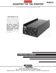
INVERTEC V300-PRO
For use with machines having Code Number : 9825 THRU 10450
Return to Master TOC
View Safety Info
View Safety Info
Safety Depends on You
Return to Master TOC
Return to Master TOC
RETURN TO MAIN MENU
Lincoln arc welding and cutting
equipment is designed and built
with safety in mind. However,
your overall safety can be
increased by proper installation
. . . and thoughtful operation on
your part. DO NOT INSTALL,
OPERATE OR REPAIR THIS
EQUIPMENT WITHOUT READING THIS MANUAL AND THE
SAFETY PRECAUTIONS CONTAINED THROUGHOUT. And,
most importantly, think before
you act and be careful.
View Safety Info
Return to Master TOC
SERVICE MANUAL
Copyright © 2007 Lincoln Global Inc.
• World's Leader in Welding and Cutting Products •
• Sales and Service through Subsidiaries and Distributors Worldwide •
Cleveland, Ohio 44117-1199 U.S.A. TEL: 216.481.8100 FAX: 216.486.1751 WEB SITE: www.lincolnelectric.com
Return to Master TOC
i
i
SAFETY
WARNING
CALIFORNIA PROPOSITION 65 WARNINGS
Diesel engine exhaust and some of its constituents
are known to the State of California to cause cancer, birth defects, and other reproductive harm.
The Above For Diesel Engines
The engine exhaust from this product contains
chemicals known to the State of California to cause
cancer, birth defects, or other reproductive harm.
The Above For Gasoline Engines
ARC WELDING CAN BE HAZARDOUS. PROTECT YOURSELF AND OTHERS FROM POSSIBLE SERIOUS INJURY OR DEATH.
KEEP CHILDREN AWAY. PACEMAKER WEARERS SHOULD CONSULT WITH THEIR DOCTOR BEFORE OPERATING.
Return to Master TOC
Return to Master TOC
Return to Master TOC
Read and understand the following safety highlights. For additional safety information, it is strongly recommended that you
purchase a copy of “Safety in Welding & Cutting - ANSI Standard Z49.1” from the American Welding Society, P.O. Box 351040,
Miami, Florida 33135 or CSA Standard W117.2-1974. A Free copy of “Arc Welding Safety” booklet E205 is available from the
Lincoln Electric Company, 22801 St. Clair Avenue, Cleveland, Ohio 44117-1199.
BE SURE THAT ALL INSTALLATION, OPERATION, MAINTENANCE AND REPAIR PROCEDURES ARE
PERFORMED ONLY BY QUALIFIED INDIVIDUALS.
FOR ENGINE
powered equipment.
1.h. To avoid scalding, do not remove the
radiator pressure cap when the engine is
hot.
1.a. Turn the engine off before troubleshooting and maintenance
work unless the maintenance work requires it to be running.
____________________________________________________
1.b. Operate engines in open, well-ventilated
areas or vent the engine exhaust fumes
outdoors.
____________________________________________________
1.c. Do not add the fuel near an open flame welding arc or when the engine is running. Stop
the engine and allow it to cool before refueling to prevent spilled fuel from vaporizing on
contact with hot engine parts and igniting. Do
not spill fuel when filling tank. If fuel is spilled,
wipe it up and do not start engine until fumes
have been eliminated.
____________________________________________________
1.d. Keep all equipment safety guards, covers and devices in position and in good repair.Keep hands, hair, clothing and tools
away from V-belts, gears, fans and all other moving parts
when starting, operating or repairing equipment.
____________________________________________________
1.e. In some cases it may be necessary to remove safety
guards to perform required maintenance. Remove
guards only when necessary and replace them when the
maintenance requiring their removal is complete.
Always use the greatest care when working near moving
parts.
___________________________________________________
1.f. Do not put your hands near the engine fan.
Do not attempt to override the governor or
idler by pushing on the throttle control rods
while the engine is running.
ELECTRIC AND
MAGNETIC FIELDS
may be dangerous
2.a. Electric current flowing through any conductor causes
localized Electric and Magnetic Fields (EMF). Welding
current creates EMF fields around welding cables and
welding machines
2.b. EMF fields may interfere with some pacemakers, and
welders having a pacemaker should consult their physician
before welding.
2.c. Exposure to EMF fields in welding may have other health
effects which are now not known.
2.d. All welders should use the following procedures in order to
minimize exposure to EMF fields from the welding circuit:
2.d.1. Route the electrode and work cables together - Secure
them with tape when possible.
2.d.2. Never coil the electrode lead around your body.
2.d.3. Do not place your body between the electrode and
work cables. If the electrode cable is on your right
side, the work cable should also be on your right side.
2.d.4. Connect the work cable to the workpiece as close as
possible to the area being welded.
___________________________________________________
1.g. To prevent accidentally starting gasoline engines while
turning the engine or welding generator during maintenance
work, disconnect the spark plug wires, distributor cap or
magneto wire as appropriate.
2.d.5. Do not work next to welding power source.
Mar ‘95
Return to Master TOC
Return to Master TOC
ii
ELECTRIC SHOCK can kill.
ARC RAYS can burn.
3.a. The electrode and work (or ground) circuits
are electrically “hot” when the welder is on.
Do not touch these “hot” parts with your bare
skin or wet clothing. Wear dry, hole-free
gloves to insulate hands.
4.a. Use a shield with the proper filter and cover
plates to protect your eyes from sparks and
the rays of the arc when welding or observing
open arc welding. Headshield and filter lens
should conform to ANSI Z87. I standards.
3.b. Insulate yourself from work and ground using dry insulation.
Make certain the insulation is large enough to cover your full
area of physical contact with work and ground.
4.b. Use suitable clothing made from durable flame-resistant
material to protect your skin and that of your helpers from
the arc rays.
In addition to the normal safety precautions, if welding
must be performed under electrically hazardous
conditions (in damp locations or while wearing wet
clothing; on metal structures such as floors, gratings or
scaffolds; when in cramped positions such as sitting,
kneeling or lying, if there is a high risk of unavoidable or
accidental contact with the workpiece or ground) use
the following equipment:
• Semiautomatic DC Constant Voltage (Wire) Welder.
• DC Manual (Stick) Welder.
• AC Welder with Reduced Voltage Control.
4.c. Protect other nearby personnel with suitable, non-flammable
screening and/or warn them not to watch the arc nor expose
themselves to the arc rays or to hot spatter or metal.
3.c. In semiautomatic or automatic wire welding, the electrode,
electrode reel, welding head, nozzle or semiautomatic
welding gun are also electrically “hot”.
3.d. Always be sure the work cable makes a good electrical
connection with the metal being welded. The connection
should be as close as possible to the area being welded.
3.e. Ground the work or metal to be welded to a good electrical
(earth) ground.
3.f. Maintain the electrode holder, work clamp, welding cable and
welding machine in good, safe operating condition. Replace
damaged insulation.
Return to Master TOC
ii
SAFETY
3.g. Never dip the electrode in water for cooling.
3.h. Never simultaneously touch electrically “hot” parts of
electrode holders connected to two welders because voltage
between the two can be the total of the open circuit voltage
of both welders.
3.i. When working above floor level, use a safety belt to protect
yourself from a fall should you get a shock.
3.j. Also see Items 6.c. and 8.
FUMES AND GASES
can be dangerous.
5.a. Welding may produce fumes and gases
hazardous to health. Avoid breathing these
fumes and gases.When welding, keep
your head out of the fume. Use enough
ventilation and/or exhaust at the arc to keep
fumes and gases away from the breathing zone. When
welding with electrodes which require special
ventilation such as stainless or hard facing (see
instructions on container or MSDS) or on lead or
cadmium plated steel and other metals or coatings
which produce highly toxic fumes, keep exposure as
low as possible and below Threshold Limit Values (TLV)
using local exhaust or mechanical ventilation. In
confined spaces or in some circumstances, outdoors, a
respirator may be required. Additional precautions are
also required when welding on galvanized steel.
5. b. The operation of welding fume control equipment is affected
by various factors including proper use and positioning of the
equipment, maintenance of the equipment and the specific
welding procedure and application involved. Worker exposure level should be checked upon installation and periodically thereafter to be certain it is within applicable OSHA PEL
and ACGIH TLV limits.
5.c. Do not weld in locations near chlorinated hydrocarbon vapors
coming from degreasing, cleaning or spraying operations.
The heat and rays of the arc can react with solvent vapors to
form phosgene, a highly toxic gas, and other irritating products.
5.d. Shielding gases used for arc welding can displace air and
cause injury or death. Always use enough ventilation,
especially in confined areas, to insure breathing air is safe.
Return to Master TOC
5.e. Read and understand the manufacturer’s instructions for this
equipment and the consumables to be used, including the
material safety data sheet (MSDS) and follow your
employer’s safety practices. MSDS forms are available from
your welding distributor or from the manufacturer.
5.f. Also see item 1.b.
AUG 06
SAFETY
Return to Master TOC
iii
WELDING SPARKS can
cause fire or explosion.
6.a. Remove fire hazards from the welding area.
If this is not possible, cover them to prevent
the welding sparks from starting a fire.
Remember that welding sparks and hot
materials from welding can easily go through small cracks
and openings to adjacent areas. Avoid welding near
hydraulic lines. Have a fire extinguisher readily available.
6.b. Where compressed gases are to be used at the job site,
special precautions should be used to prevent hazardous
situations. Refer to “Safety in Welding and Cutting” (ANSI
Standard Z49.1) and the operating information for the
equipment being used.
Return to Master TOC
6.c. When not welding, make certain no part of the electrode
circuit is touching the work or ground. Accidental contact can
cause overheating and create a fire hazard.
6.d. Do not heat, cut or weld tanks, drums or containers until the
proper steps have been taken to insure that such procedures
will not cause flammable or toxic vapors from substances
inside. They can cause an explosion even though they have
been “cleaned”. For information, purchase “Recommended
Safe Practices for the Preparation for Welding and Cutting of
Containers and Piping That Have Held Hazardous
Substances”, AWS F4.1 from the American Welding Society
(see address above).
6.e. Vent hollow castings or containers before heating, cutting or
welding. They may explode.
6.f. Sparks and spatter are thrown from the welding arc. Wear oil
free protective garments such as leather gloves, heavy shirt,
cuffless trousers, high shoes and a cap over your hair. Wear
ear plugs when welding out of position or in confined places.
Always wear safety glasses with side shields when in a
welding area.
Return to Master TOC
iii
6.g. Connect the work cable to the work as close to the welding
area as practical. Work cables connected to the building
framework or other locations away from the welding area
increase the possibility of the welding current passing
through lifting chains, crane cables or other alternate circuits.
This can create fire hazards or overheat lifting chains or
cables until they fail.
6.h. Also see item 1.c.
CYLINDER may explode
if damaged.
7.a. Use only compressed gas cylinders
containing the correct shielding gas for the
process used and properly operating
regulators designed for the gas and
pressure used. All hoses, fittings, etc. should be suitable for
the application and maintained in good condition.
7.b. Always keep cylinders in an upright position securely
chained to an undercarriage or fixed support.
7.c. Cylinders should be located:
• Away from areas where they may be struck or subjected to
physical damage.
• A safe distance from arc welding or cutting operations and
any other source of heat, sparks, or flame.
7.d. Never allow the electrode, electrode holder or any other
electrically “hot” parts to touch a cylinder.
7.e. Keep your head and face away from the cylinder valve outlet
when opening the cylinder valve.
7.f. Valve protection caps should always be in place and hand
tight except when the cylinder is in use or connected for
use.
7.g. Read and follow the instructions on compressed gas
cylinders, associated equipment, and CGA publication P-l,
“Precautions for Safe Handling of Compressed Gases in
Cylinders,” available from the Compressed Gas Association
1235 Jefferson Davis Highway, Arlington, VA 22202.
FOR ELECTRICALLY
powered equipment.
8.a. Turn off input power using the disconnect
switch at the fuse box before working on
the equipment.
8.b. Install equipment in accordance with the U.S. National
Electrical Code, all local codes and the manufacturer’s
recommendations.
8.c. Ground the equipment in accordance with the U.S. National
Electrical Code and the manufacturer’s recommendations.
Return to Master TOC
Mar ‘95
Return to Master TOC
Return to Master TOC
Return to Master TOC
Return to Master TOC
iv
iv
SAFETY
PRÉCAUTIONS DE SÛRETÉ
Pour votre propre protection lire et observer toutes les instructions
et les précautions de sûreté specifiques qui parraissent dans ce
manuel aussi bien que les précautions de sûreté générales suivantes:
Sûreté Pour Soudage A L’Arc
1. Protegez-vous contre la secousse électrique:
a. Les circuits à l’électrode et à la piéce sont sous tension
quand la machine à souder est en marche. Eviter toujours
tout contact entre les parties sous tension et la peau nue
ou les vétements mouillés. Porter des gants secs et sans
trous pour isoler les mains.
b. Faire trés attention de bien s’isoler de la masse quand on
soude dans des endroits humides, ou sur un plancher metallique ou des grilles metalliques, principalement dans
les positions assis ou couché pour lesquelles une grande
partie du corps peut être en contact avec la masse.
c. Maintenir le porte-électrode, la pince de masse, le câble de
soudage et la machine à souder en bon et sûr état defonctionnement.
d.Ne jamais plonger le porte-électrode dans l’eau pour le
refroidir.
e. Ne jamais toucher simultanément les parties sous tension
des porte-électrodes connectés à deux machines à souder
parce que la tension entre les deux pinces peut être le total
de la tension à vide des deux machines.
f. Si on utilise la machine à souder comme une source de
courant pour soudage semi-automatique, ces precautions
pour le porte-électrode s’applicuent aussi au pistolet de
soudage.
2. Dans le cas de travail au dessus du niveau du sol, se protéger
contre les chutes dans le cas ou on recoit un choc. Ne jamais
enrouler le câble-électrode autour de n’importe quelle partie du
corps.
3. Un coup d’arc peut être plus sévère qu’un coup de soliel, donc:
zones où l’on pique le laitier.
6. Eloigner les matériaux inflammables ou les recouvrir afin de
prévenir tout risque d’incendie dû aux étincelles.
7. Quand on ne soude pas, poser la pince à une endroit isolé de
la masse. Un court-circuit accidental peut provoquer un
échauffement et un risque d’incendie.
8. S’assurer que la masse est connectée le plus prés possible de
la zone de travail qu’il est pratique de le faire. Si on place la
masse sur la charpente de la construction ou d’autres endroits
éloignés de la zone de travail, on augmente le risque de voir
passer le courant de soudage par les chaines de levage,
câbles de grue, ou autres circuits. Cela peut provoquer des
risques d’incendie ou d’echauffement des chaines et des
câbles jusqu’à ce qu’ils se rompent.
9. Assurer une ventilation suffisante dans la zone de soudage.
Ceci est particuliérement important pour le soudage de tôles
galvanisées plombées, ou cadmiées ou tout autre métal qui
produit des fumeés toxiques.
10. Ne pas souder en présence de vapeurs de chlore provenant
d’opérations de dégraissage, nettoyage ou pistolage. La
chaleur ou les rayons de l’arc peuvent réagir avec les vapeurs
du solvant pour produire du phosgéne (gas fortement toxique)
ou autres produits irritants.
11. Pour obtenir de plus amples renseignements sur la sûreté, voir
le code “Code for safety in welding and cutting” CSA Standard
W 117.2-1974.
PRÉCAUTIONS DE SÛRETÉ POUR
LES MACHINES À SOUDER À
TRANSFORMATEUR ET À
REDRESSEUR
a. Utiliser un bon masque avec un verre filtrant approprié ainsi
qu’un verre blanc afin de se protéger les yeux du rayonnement de l’arc et des projections quand on soude ou
quand on regarde l’arc.
b. Porter des vêtements convenables afin de protéger la peau
de soudeur et des aides contre le rayonnement de l‘arc.
c. Protéger l’autre personnel travaillant à proximité au
soudage à l’aide d’écrans appropriés et non-inflammables.
1. Relier à la terre le chassis du poste conformement au code de
l’électricité et aux recommendations du fabricant. Le dispositif
de montage ou la piece à souder doit être branché à une
bonne mise à la terre.
4. Des gouttes de laitier en fusion sont émises de l’arc de
soudage. Se protéger avec des vêtements de protection libres
de l’huile, tels que les gants en cuir, chemise épaisse, pantalons sans revers, et chaussures montantes.
3. Avant de faires des travaux à l’interieur de poste, la debrancher à l’interrupteur à la boite de fusibles.
2. Autant que possible, I’installation et l’entretien du poste seront
effectués par un électricien qualifié.
4. Garder tous les couvercles et dispositifs de sûreté à leur place.
5. Toujours porter des lunettes de sécurité dans la zone de
soudage. Utiliser des lunettes avec écrans lateraux dans les
Mar. ‘93
v
v
RETURN TO MAIN MENU
MASTER TABLE OF CONTENTS FOR ALL SECTIONS
Safety . . . . . . . . . . . . . . . . . . . . . . . . . . . . . . . . . . . . . . . . . . . . . . . . . . . . . . . .
i-iv
Installation . . . . . . . . . . . . . . . . . . . . . . . . . . . . . . . . . . . . . . . . . . . . . . . . . . . . Section A
Operation . . . . . . . . . . . . . . . . . . . . . . . . . . . . . . . . . . . . . . . . . . . . . . . . . . . . . Section B
Accessories . . . . . . . . . . . . . . . . . . . . . . . . . . . . . . . . . . . . . . . . . . . . . . . . . . Section C
Maintenance . . . . . . . . . . . . . . . . . . . . . . . . . . . . . . . . . . . . . . . . . . . . . . . . . . Section D
Theory of Operation . . . . . . . . . . . . . . . . . . . . . . . . . . . . . . . . . . . . . . . . . . . . Section E
Troubleshooting and Repair . . . . . . . . . . . . . . . . . . . . . . . . . . . . . . . . . . . . . Section F
Electrical Diagrams . . . . . . . . . . . . . . . . . . . . . . . . . . . . . . . . . . . . . . . . . . . . Section G
Parts Manual . . . . . . . . . . . . . . . . . . . . . . . . . . . . . . . . . . . . . . . . . . . . . . . . . .P243 Series
V300-I
TABLE OF CONTENTS
- INSTALLATION SECTION -
Technical Specifications .........................................................................................A-2
Location ..................................................................................................................A-3
Electrical Installation ...............................................................................................A-3
Input Connections...................................................................................................A-4
Wire feeder and Accessory Connections ........................................................A-4, A-5
Output Connection..................................................................................................A-6
Return to Master TOC
Return to Master TOC
Section A-1
Installation ..............................................................................................................Section A
Return to Master TOC
Return to Master TOC
Section A-1
V300-PRO
INSTALLATION
Return to Master TOC
Return to Section TOC
A-2
A-2
TECHNICAL SPECIFICATIONS - V300-PRO (K1349-3, K1349-4)
INPUT
THREE PHASE
Standard
Voltage
208/230/460/575
50/60
SINGLE PHASE
Input Current
Code
at Rated Output
Number
48/43/24/20
9825,9834,9965
10034,10035
10130,10131
Standard
Voltage
208/230/460
50/60
Input Current
Code
at Rated Output
Number
69/62/389825,9936,9965
10034, 10130,
RATED OUTPUT
Return to Master TOC
Return to Master TOC
Return to Section TOC
Return to Section TOC
THREE PHASE
SINGLE PHASE
Volts at
Rated
Amperes
32
30
Amps
300
250
Duty Cycle
60% Duty Cycle
100% Duty Cycle
Duty Cycle
60% Duty Cycle
100% Duty Cycle
Volts at
Rated
Amperes
28
26.5
Amps
200
165
OUTPUT
THREE PHASE
Welding
Current Range
5-300 Amps
Constant Open
Circuit Voltage
60-70 VDC
SINGLE PHASE
Auxiliary
Power
42 VAC, 5.5 Amps
24 VAC, 1 Amp
*115 VAC, 2 Amps
*Not on all codes
Welding
Current Range
5-200 Amps
Constant Open
Circuit Voltage
60-70 VDC
Auxiliary
Power
42 VAC, 5.5 Amps
24 VAC, 1 Amp
*115 VAC, 2 Amps
*Not on all codes
RECOMMENDED INPUT WIRE AND FUSE SIZES
THREE PHASE
SINGLE PHASE
Input
Voltage
Frequency(1)
208/60
230/60
460/60
575/60
Fuse
Input
(Superlag) Ampere
or
Rating
Breaker
on
Size
Nameplate
60
60
40
30
48
39
25
25
Type 75°C
Copper
Wire in
Conduit
AWG (IEC)
Sizes
Type 75°C
Copper
Ground
Wire in
Conduit
AWG (IEC)
Sizes
6 (16mm2)
8 (10mm2)
10 (6mm2)
10 (6mm2)
10
10
10
10
(6mm2)
(6mm2)
(6mm2)
(6mm2)
Input
Voltage
Frequency(1)
Fuse
Input
(Superlag) Ampere
or
Rating
Breaker
on
Size
Nameplate
208/60
230/60
460/60
85
80
50
69
62
38
Type 75°C
Copper
Wire in
Conduit
AWG (IEC)
Sizes
Type 75°C
Copper
Ground
Wire in
Conduit
AWG (IEC)
Sizes
6 (16mm2)
6 (16mm2)
8 (10mm2)
10 (6mm2)
10 (6mm2)
10 (6mm2)
Return to Master TOC
Return to Section TOC
PHYSICAL DIMENSIONS
Height
18.7 in.
Width
10.8 in.
Depth
22.2 in.
Weight
64 lbs.
475 mm
274 mm
564 mm
29 Kg
V300-PRO
INSTALLATION
Return to Master TOC
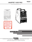
PRODUCT DESCRIPTION
ELECTRICAL INSTALLATION
The Invertec V300-PRO is a 300 amp arc welding
power source that utilizes single or three phase input
power to produce either constant voltage or constant
current outputs. The V300-PRO is designed for 50/60
Hz supply systems. The welding response of the
Invertec has been optimized for GMAW, SMAW, TIG
and FCAW processes. It is designed to be used with
the LN-25 and LN-7 semiautomatic wire feeders.
WARNING
Return to Master TOC
Return to Master TOC
Return to Master TOC
Return to Section TOC
Return to Section TOC
ELECTRIC SHOCK can kill.
Return to Section TOC
A-3
• Have an electrician install and service this equipment.
• Turn the input power off at the fuse
box before working on equipment.
• Do not touch electrically hot parts.
----------------------------------------------------------------------
1. The Invertec should be connected only by a qualified electrician. Installation should be made in
accordance with the U.S. National Electrical Code,
all local codes and the information detailed below.
2. When received from the factory, multiple voltage
(208/230/460) machines are internally connected
for 460 volt input.
3. Single voltage, 575 VAC machines, can only be
connected to 575 VAC. No internal reconnection
for other input voltages is possible.
4. Initial 208 VAC and 230 VAC operation will require
a voltage panel setup, as will later reconnection
back to 460 VAC:
a.
LOCATION
The Invertec has been designed with many features to
protect it from harsh environments. Even so, it is
important that simple preventative measures are followed in order to assure long life and reliable operation.
• The machine must be located where there is free circulation of clean air such that air movement into the
sides and out the bottom and front will not be
restricted. Dirt and dust that can be drawn into the
machine should be kept to a minimum. Failure to
observe these precautions can result in excessive
operating temperatures and nuisance shutdown of
the Invertec.
• Keep machine dry. Shelter from rain and snow. Do
not place on wet ground or in puddles.
b.
c.
Open the access panel on the right side of
the machine.
For 208 or 230: Position the large switch to
200-230.
For 460: Position the large switch to 380-460.
Move the “A” lead to the appropriate terminal.
CAUTION: DO NOT CHANGE SWITCH
POSITION WITH INPUT POWER
APPLIED. MAJOR DAMAGE WILL
RESULT.
INPUT VOLTAGE SETUP
RECONNECT PROCEDURE
. Disconnect input power before
1. BE SURE POWER SWITCH IS OFF.
.
2. CONNECT LEAD 'A' TO DESIRED
INPUT VOLTAGE RANGE.
.
440-460V
CAUTION
'A'
380-415V
DO NOT ATTEMPT TO POWER THIS UNIT
FROM THE AUXILIARY POWER SUPPLY
OF AN ENGINE WELDER.
• Special protection circuits may operate, causing
loss of output.
• The supply from engine welders often has excessive voltage peaks because the voltage waveform is
usually triangular shaped instead of sinusoidal.
• If voltage peaks from the engine welder are too high
(380v on 230v setting), the input circuits of this
machine protecting the filter capacitors, FETS and
other components from damage will not be energized.
.
Return to Section TOC
A-3
220-230V
inspecting or servicing machine.
Do not operate with wraparound
removed.
Do not touch electrically live parts.
Only qualified persons should install,
use or service this equipment.
IF MACHINE CEASES TO OPERATE (NO METER, NO FAN)
AND THERE IS NO OTHER KNOWN FAILURE: CHECK FUSE;
200-208V
REPLACE WITH A 3 AMP SLOW BLOW ONLY.
3. POSITION SWITCH TO DESIRED INPUT VOLTAGE RANGE.
VOLTAGE=380-460V
THE LINCOLN ELECTRIC CO.
V300-PRO
CLEVELAND, OHIO U.S.A.
VOLTAGE=200-230V
9-11-92
S20324
INSTALLATION
Return to Master TOC
Return to Section TOC
A-4
CONNECTION OF WIRE FEEDERS TO
THE INVERTEC
POWER INPUT CONNECTION
Connect terminal marked
to earth ground per any
existing local or national electrical codes.
LN-25 Connection Instructions
Single Phase Input
1. Turn the Invertec power switch “off”.
Connect the supply lines to the upper and lower terminals of the line switch. Torque to 27.5in.-lbs.(3.0 Nm).
Do not use center terminal of the line switch.
2. Connect the electrode cable to the output terminal
of polarity required by electrode. Connect the work
lead to the other terminal.
Three Phase Input
3. LN-25 with remote control options K431 and K432.
Use K876 adapter with K432 cable or modify K432
cable with K867 universal adapter plug. See connection diagram S19899 and S19309 or S19405 in
Operator’s Mamual.
Return to Master TOC
Connect the supply lines to the line switch. Torque to
27.5in.-lbs.(3.0 Nm).
Return to Section TOC
A-4
Install in accordance with all local and national electric
codes.
The V300-PRO is supplied with one cord connector to
provide strain relief for the input power cord. It is
designed for a cord diameter of .310-1.070” (7.9 27.2mm). The jacketed portion of the cord must go
through the connector before tightening the connector
screws.
4. Place the local-remote switch in the “remote” position if output control is desired at the wire feeder
rather than the Invertec. (LN-25 must have K431
and K432 options for remote output control operation).
LN-7 Connection Instructions (not applicable to
IEC machines with only 42V Aux.).
1. Turn the Invertec power switch “off”.
Return to Master TOC
Return to Section TOC
Recommended Fuse Sizes Based On The U.S.
National Electrical Code And Maximum Machine
Outputs
3 phase
50/60 Hz
1 phase
50/60 Hz
Return to Master TOC
Return to Section TOC
(1)
Input Volts(1)
Fuse Size in Amps
(Time Delay Fuses)
208
230
460
575
60
60
40
25
208
230
460
85
80
50
Input voltage must be within ±10% of rated value.
2. Connect the K480 or K1818-10 control cable from
the LN-7 to the Invertec control cable connector.
The control cable connector is located at the rear
of the Invertec.
3. Connect the electrode cable to the output terminal
of polarity required by electrode. Connect the work
lead to the other terminal.
4. Place the local-remote switch in the “local” position
to allow output control at the Invertec. (K864
remote control adapter and K857 remote control
are required for remote output control. See connection diagram S19901.
5. Set the meter polarity switch on the rear of the
Invertec to coincide with wire feeder polarity used.
The wire feeder will now display the welding voltage.
6. If a K480 or K1818-10 is not available, see connection diagram S19404 for modification of K291
or K404 LN-7 input cable with K867 universal
adapter plug..
V300-PRO
Return to Master TOC
Return to Section TOC
A-5
INSTALLATION
LN-9 GMA Connection Instructions (Not applicable
to machines with only 42V Aux.)
K900-1 DC TIG STARTER CONNECTION
1. Turn the Invertec power switch “off”.
This versatile new kit was made to mate with the
Invertec
2. Connect the K596 or K1820-10 control cable
assembly from the LN-9 GMA to the Invertec control
cable connector. The control cable connector is
located at the rear of the Invertec.
3. Connect the electrode cable to the output terminal
of polarity required by electrode. Connect the work
lead to the other terminal.
Return to Master TOC
Return to Section TOC
4. Place the local-remote switch in the “remote” position to allow output control at the LN-9 GMA.
5. Set the meter polarity switch on the rear of the
Invertec to coincide with wire feeder polarity used.
The wire feeder will now display the welding voltage.
6. K608-1* adapter is required in LN-9 GMA for LN-9
type control. K608-1 is installed in line with P10. See
connection diagram S20607.
7. K442-1* Pulse Power Filter Board is also required
for GMAW,but should beremoved for FCAW.
Return to Master TOC
Return to Section TOC
8. If K596 is not available, see connection diagram
S20608 for modification of K196 LN-9 GMA input
cable with K867 universal adapter plug.
* These kits are no longer available.
GENERAL INSTRUCTIONS FOR CONNECTION OF WIRE FEEDERS TO INVERTEC
Wire feeders other than LN-7 and LN-25 may be used
provided that the auxiliary power supply capacity of the
Invertec is not exceeded. K867 universal adapter plug
is required. See connection diagram S19406 and
S19386 for more information.
Remote Control of Invertec
Remote control K857, hand amptrol K963 and foot
amptrol K870 require K864 remote control adapter.
See connection diagram S19309.
Return to Master TOC
Return to Section TOC
A-5
A control cable assembly is supplied with the kit to
connect the kit to an Invertec. The cable can be connected, either end, at the DC TIG Starter kit and at
the Invertec by attaching to the 14-pin Amphenols on
the backs of each unit. See diagram S20405.
A negative output cable assembly is also supplied
with the DC TIG Starter kit to connect the kit with the
Invertec’s negative output terminal.
All Magnum™ one and two piece water-cooled
torches with 7/8 left-hand threads and gas-cooled
torches with 7/8 and 5/16 right-hand threads can be
connected to the starter kit.
To secure the DC TIG Starter kit to the bottom of the
Invertec and for more detailed instructions, see the
K900-1 (IM465) manual.
PARALLEL OPERATION
The Invertec is operable in parallel in both CC and
CV modes. For best results, the currents of each
machine should be reasonably well shared. As an
example, with two machines set up in parallel for a
400 amp procedure, each machine should be set to
deliver approximately 200 amps, not 300 amps from
one and 100 amps from the other. This will minimize
nuisance shutdown conditions. In general, more than
two machines in parallel will not be effective due to
the voltage requirements of procedures in that power
range.
To set machine outputs, start with output control pots
and arc force/pinch pots in identical positions. If running in a CC mode, adjust output and arc force to
maintain current sharing while establishing the proper output current. In CV modes, set the pots to identical positions. Then switch the machine meters to
read amps and adjust one of the output control pots
for current balance. Check the voltage and if readjustment is necessary, repeat the current balancing
step. Pinch settings should also be kept identical on
the machines.
K954-1 MIG PULSER
The MIG Pulser is a hand-held “pendant” type GMAW
Pulsing option for the V300-PRO Power Source. See
the Mig Pulser’s IM manual (IM555) for connection
information.
V300-PRO
INSTALLATION
Return to Master TOC
Return to Section TOC
A-6
A-6
OUTPUT CABLES
Select the output cable size based upon the following
chart.
Cable sizes for Combined Length of Electrode and
Work Cable (Copper) 75° rated:
Duty
Cycle
Current
Length Up
61m (200 ft.)
61-76m
(200-250 ft.)
100%
60%
250
300
1/0
1/0
1/0
2/0
Return to Master TOC
Return to Section TOC
QUICK DISCONNECT PLUGS (K852-7)
A quick disconnect system is used for the welding
cable connections. The welding plug included with the
machine is designed to accept a welding cable size of
1/0 to 2/0.
BOOT
1. Remove 1 inch (25mm) of welding cable insulation.
2. Slide rubber boot on to the cable end. The boot
end may be trimmed to match the cable diameter.
Soap or other lubricant will help to slide the boot
over the cable.
Return to Master TOC
Return to Master TOC
4. Insert the cable into the copper tube.
Return to Section TOC
25 mm
5. Tighten set screw to collapse copper tube. The
screw must apply pressure against welding cable.
The top of the set screw will be well below the surface of the brass plug after tightening.
6. Slide the rubber boot over the brass plug. The rubber boot must be positioned to completely cover all
electrical surfaces after the plug is locked into the
receptacle.
V300-PRO
TRIM
1 in.
m&
m
5
2
rse
reve
3. Slide the copper tube into the brass plug.
Return to Section TOC
WELDING CABLE
1in
SET SCREW
BRASS PLUG
COPPER TUBE
TABLE OF CONTENTS
- OPERATION SECTION -
Operating Instructions ........................................................................................... B-2
Controls and Settings .................................................................................... B-2, B-4
Auxillary Power ..................................................................................................... B-4
Return to Master TOC
Return to Master TOC
Section B-1
Operation ................................................................................................................Section B
Return to Master TOC
Return to Master TOC
Section B-1
V300-PRO
OPERATION
Return to Master TOC
Return to Master TOC
Return to Section TOC
Return to Section TOC
B-2
OPERATING INSTRUCTIONS
B-2
OUTPUT CONTROL - This controls the output voltage
in the CV modes and output current in the CC modes.
WARNING
ELECTRIC SHOCK can kill.
• Do not touch electrically live parts or
electrode with skin or wet clothing.
• Insulate yourself from work and
ground.
• Always wear dry insulating gloves.
-----------------------------------------------------------------------FUMES AND GASES can be dangerous.
• Keep your head out of fumes.
• Use ventilation or exhaust to remove
fumes from breathing zone.
----------------------------------------------------------------------WELDING SPARKS can cause fire or
explosion.
• Keep flammable material away.
• Do not weld on closed containers.
-----------------------------------------------------------------------ARC RAYS can burn eyes and skin.
• Wear eye, ear and body
protection.
Control is provided over the entire output range of the
power source with 1 turn of the control knob. This control may be adjusted while under load to change power
source output.
OUTPUT
LOCAL/REMOTE SWITCH - Place in the “LOCAL”
position to allow output adjustment at the machine.
Place in the “REMOTE” position to allow output adjustment at the wire feeder or with a remote control option
package.
REMOTE
Return to Master TOC
Return to Section TOC
-----------------------------------------------------------See additional warning information at
front of this operator’s manual.
----------------------------------------------------------DUTY CYCLE
The Invertec is rated at 300 amps, 60% duty cycle for
3 phase inputs (based on a 10 minute cycle). It is also
rated at 250 amps, 100% duty cycle.
CONTROL FUNCTION / OPERATION
DIGITAL METER SWITCH - Select either “A” for amps
or “V” for volts to display welding current or voltage on
the meter.
When welding current is not present, the meter will display the set current for the CC modes or the set voltage for the CV modes. This set reading is an indication
of machine control setting. For a more precise process
reading, read meter during actual welding.
Return to Master TOC
Return to Section TOC
POWER SWITCH - Place the lever in the “ON” position
to energize the machine. When the power is on, the
digital meter will activate and the fan will operate.
OFF
.
V300-PRO
OPERATION
Return to Master TOC
Return to Section TOC
B-3
MODE SWITCH
ARC FORCE/INDUCTANCE CONTROL
GTAW
Optimized for both scratch start and HiFreq kit use.
CC SOFT
Best for EXX18 thru EXX28 stick electrodes.
This control functions in all modes except GTAW. For
CC modes, this control acts as an Arc Force adjustment. The arc is soft at the minimum settings and more
forceful or driving at the maximum settings. Higher
spatter levels may be present at the maximum settings.
CC Crisp
Use this mode for stick welding with
EXX10 thru EXX14 electrodes. Nonwelding applications such as resistive
heating or output tests with resistive
loads should be done in this mode with
Arc Force Control set to minimum.
This setting has been optimized for
Innershield® and Outershield® flux-cored
electrodes.
Return to Master TOC
CV FCAW
Return to Section TOC
B-3
CV GMAW
For CV modes, this control will set the degree of “pinch
effect” which predominantly affects short circuit transfer. In FCAW, the maximum setting is generally preferred. With GMAW, the upper half of the range is preferred with CO2 or high content CO2 mixed gas. The
lower half is for inert gas mixes.
Short circuit, glob and spray transfer
solid wire and gas welding are done in
this mode. Low end procedures, less
than 16V, may operate better in the
FCAW mode.
SMAW
CRISP
FCAW
SMAW
SOFT
GMAW
RECOMMENDED SETTINGS FOR SELECTED
APPLICATIONS
Full Range Is 1-10,
1 Is Very Soft, 10 Is Very Crisp
Return to Master TOC
Return to Section TOC
GTAW
OUTPUT TERMINALS SWITCH
For processes and equipment that require energized
machine terminals (stick, TIG, air-carbon arc cutting or
hot tip LN-25), set the Output Terminals Switch to “ON”
position.
Return to Master TOC
Return to Section TOC
Set to the REMOTE (OFF) position when using LN-25
with K431/K432 or K624-1 options or other wirefeeders
which allow the gun trigger to energize the welding terminals.
Nominal
Setting
Recommended
Adjustment Range
EXX18 thru
EXX28 stick
5
1 (gentle, may stick) to 9
(forceful, more spatter)
EXX10 thru
EXX14 stick
6
3 to 10
Air Carbon Arc
Cutting
1
None
Innershield or
Outershield
10
None
Air Carbon Arc
Cutting
1
None
7.5
5 to 10
5
1 to 10
Mode
Process
CC SMAW 1
CC SMAW 2
CV FCAW
CV GMAW* CO2 or 25% CO2
or similar
gas mixes
ON
98% Ar-2% O2Ar,
90% He-7.5% Ar
2.5% CO2 and
OUTPUT
TERMINALS
other
predominantly
inert gases
REMOTE
* 1 = Lowest pinch, highest inductance and least spatter.
10 = Highest pinch, lowest inductance and most spatter.
V300-PRO
OPERATION
Return to Master TOC
Return to Section TOC
B-4
B-4
METER POLARITY SWITCH
AUXILIARY POWER
The wire feeder polarity switch is located at the rear of
the machine. The switch provides a work connection
for wire feeder voltmeters. Place the switch in the position of the electrode polarity indicated by the decal.
The switch does not change the welding polarity.
A 24 VAC @ 1 amp supply is included for use with the
LN-25 wire feeder (24 volts needed for K431 and
K432 options). This supply is protected by a selfresetting current limiter.
A 42 VAC @ 5.5 amp supply is included for use with
other wire feeders. This supply is protected by a 6
amp breaker located on the rear of the machine.
T13086-84
Return to Master TOC
Return to Master TOC
Return to Master TOC
Return to Section TOC
Return to Section TOC
Return to Section TOC
A 110/115 VAC @ 2 amp supply is included for use
with the LN-7 or LN-9 GMA wire feeders. This supply
is protected by a 2.5 amp breaker located on the rear
of the machine. It is NOT available on IEC units.
All three supplies are not to be loaded simultaneously
LINCOLN
-
+
OUTPUT TERMINALS
V300-PRO
TABLE OF CONTENTS
- ACCESSORIES SECTION -
Options/Accessories...............................................................................................C-2
Return to Master TOC
Return to Master TOC
Section C-1
Accessories ............................................................................................................Section C
Return to Master TOC
Return to Master TOC
Section C-1
V300-PRO
Return to Master TOC
Return to Section TOC
C-2
ACCESSORIES
OPTIONS / ACCESSORIES
C-2
K876 REMOTE CONTROL
ADAPTER
CABLE PLUGS
Cable Plug Kit for 1/0-2/0 cable (K852-70) attaches to
welding cable to provide quick disconnect from
machine.
For operating an LN-25 wire feeder. The adapter
connects to the 14-pin receptacle of Invertec power
sources and to the 6-pin connector of the LN-25
K432 remote control cable.
Cable Plug Kit for 2.0-3/0 cable (K852-95).
K900-1 DC TIG STARTER
NOTE: Two K852-70 plugs are included with the V300-I.
Solid state GTAW starting unit. Rated 300 A, 60%.
Return to Master TOC
Return to Section TOC
K864 REMOTE CONTROL
ADAPTER
Plugs into the 14-pin receptacle on the rear panel of the
Invertec. Adapter splits remote control circuitry to a 6pin receptacle and to a 14-pin receptacle. Adapter permits remote output control of Invertec by means of
K857 Remote Control, K812 Hand Amptrol or K870
Foot Amptrol. Allows remote while using LN-7 K480-7
control cable.
Return to Section TOC
Return to Master TOC
Return to Section TOC
Return to Master TOC
K867 UNIVERSAL ADAPTER
PLUG
Consisting of a 14-pin plug connected to labeled wires,
the adapter allows user connection of any suitable
accessory or wire feeder to the remote control, contactor, and auxiliary power circuitry of the Invertec.
V300-PRO
TABLE OF CONTENTS
- MAINTENANCE SECTION -
Input Filter Capacitor Discharge Procedure ..........................................................
Preventive maintenance........................................................................................
Overload/Thermal Protection ................................................................................
Printed Circuit Board Replacement.......................................................................
Return to Master TOC
Return to Master TOC
Section D-1
Maintenance ...........................................................................................................Section D
Return to Master TOC
Return to Master TOC
Section D-1
V300-PRO
D-2
D-3
D-3
D-3
MAINTENANCE
Return to Master TOC
Return to Section TOC
D-2
WARNING
Failure to follow this capacitor
discharge procedure can result
in electric shock.
Return to Master TOC
Return to Section TOC
5. Locate the two capacitor terminals (large hex
head capscrews)shown in Figure D.1.
6. Use electrically insulated gloves and insulated pliers. Hold body of the resistor and connect resistor
leads across the two capacitor terminals. Hold
resistor in place for 10 seconds. DO NOT TOUCH
CAPACITOR TERMINALS WITH YOUR BARE
HANDS.
INPUT FILTER CAPACITOR
DISCHARGE PROCEDURE
1. Turn off input power or disconnect input power
lines.
2. Remove 14 5/16” hex head screws from side and
top of machine (6 screws on each side and 2
screws on top) and remove wrap-around machine
cover.
3. Be careful not to make contact with the capacitor
terminals that are located in the center of the
Switch Boards.
7. Repeat discharge procedure for capacitor on
other side of machine. If you are working on a
575 VAC machine, repeat discharge procedure
for second capacitor on each side of machine.
8. Check voltage across terminals of all capacitors
with a DC voltmeter. Polarity of capacitor terminals is marked on PC board above terminals.
Voltage should be zero. If any voltage remains,
repeat this capacitor discharge procedure.
4. Obtain a high resistance and high wattage resistor (25-1000 ohms and 25 watts minimum). This
resistor is not supplied with machine. NEVER
USE A SHORTING STRAP FOR THIS PROCEDURE.
.
Return to Section TOC
Return to Master TOC
Return to Master TOC
FIGURE D.1 — LOCATION OF INPUT FILTER CAPACITOR TERMINALS.
Return to Section TOC
D-2
V300-PRO
Return to Master TOC
Return to Section TOC
D-3
MAINTENANCE
D-3
PREVENTIVE MAINTENANCE
OVERLOAD PROTECTION
1. Perform the following preventive maintenance
procedures at least once every six months. It is
good practice to keep a preventive maintenance
record; a record tag attached to the machine
works best.
The machine is electrically protected from producing
high output currents. Should the output current
exceed 340-360A, an electronic protection circuit will
reduce the current (“Fold Back”) to approximately
150A. The machine will continue to produce this low
current until the protection circuit is reset. Reset
occurs when the output load is removed.
2. Remove the machine wrap-around cover and perform the input filter capacitor discharge procedure
(detail at the beginning of this chapter).
Return to Master TOC
Return to Section TOC
THERMAL PROTECTION
3. Clean the inside of the machine with a low pressure airstream. Be sure to clean the following
components thoroughly. See Figure D.2 for location of these components.
• Power Switch, Driver, Protection, and Control
printed circuit boards
• Power Switch
Thermostats protect the machine from excessive
operating temperatures. Excessive temperatures
may be caused by a lack of cooling air or operating
the machine beyond the duty cycle and output rating. If excessive operating temperature should
occur, the thermostat will prevent output voltage or
current. The meter will remain energized during this
time.
• Main Transformer
PC BOARD REPLACEMENT
• Input Rectifier
1. Handle PC Boards by edges only.
• Heat Sink Fins
2. Store PC Boards only in the bags that disperse
static charges.
Return to Master TOC
Return to Master TOC
Return to Section TOC
Return to Section TOC
• Input Filter Capacitors
• Output Terminals
4. Examine capacitors for leakage or oozing.
Replace if needed.
5. Examine wrap-around cover for dents or breakage. Repair as needed. Cover must be kept in
good condition to assure high voltage parts are
protected and correct spacings are maintained.
6. Check electrical ground continuity. Using an ohmmeter, measure resistance between either output
stud and an unpainted surface of the machine
case. (See Figure D.2 for locations.) Meter reading should be 500,000 ohms or more. If meter
reading is less than 500,000 ohms, check for
electrical components that are not properly insulated from the case. Correct insulation if needed.
3. Inspect PC Board for burned conductors or components. If damage is visible, inspect the
machine wiring for grounds or shorts to avoid
damaging a new PC Board.
4. If there is no visible damage to the PC Board,
install a new PC Board and see if the problem is
fixed. If the problem is fixed by the new board,
reinstall the old board and see if the problem
reoccurs. If the problem does not reoccur, check
the wiring harness and plugs for loose connections.
7. Replace machine cover and screws.
V300-PRO
MAINTENANCE
Return to Section TOC
Return to Master TOC
Return to Section TOC
Return to Master TOC
D-4
D-4
FIGURE D.2 — LOCATION OF MAINTENANCE COMPONENTS.
3
4
2
5
1
Return to Master TOC
Return to Section TOC
11
6
10
7
Return to Master TOC
Return to Section TOC
COMPONENT
PC BOARDS
CONTROL
DRIVER
PROTECTION
SWITCH
POWER
INPUT RECTIFIER
POWER SWITCH
HEAT SINK FINS
MAIN TRANSFORMER
OUTPUT STUDS
INPUT FILTER CAPACITORS
QTY,
ITEM
NO.
1
1
1
2
1
1
1
2
1
1
2
1
2
3
7
10
4
5
6
8
9
11
8
9
V300-PRO
TABLE OF CONTENTS
- THEORY OF OPERATION SECTION -
Return to Master TOC
Section E-1
Theory of Operation ...............................................................................................Section E
Return to Master TOC
Power Supply Operation ......................................................................................E-2
Pre Charge and Protection Circuitry ....................................................................E-3
Switch Board and Main Transformer....................................................................E-4
Control and Output Circuitry ................................................................................E-5
Field Effect Transistor (FET) Operation ...............................................................E-6
Pulse Width Modulation .......................................................................................E-7
Protective Circuits ................................................................................................E-8
FIGURE E.1 – V300-PRO BLOCK LOGIC DIAGRAM
POWER SWITCH
SECTIONS
20KHZ
LEFT SWITCH BOARD
MAIN
TRANSFORMER
Return to Master TOC
FET MODULES
CHOKE
RECTIFIER
HEATSINK
TOP
CAP
1 DIODE
FET MODULES
CURRENT
TRANSFORMER
1ø OR 3ø DETETCTION (H5)
PRE-CHARGE
INPUT
RECTIFIER
LINE
SWITCH
DRIVER
BOARD
3A
AC1
AC2
AC3
5 DIODES
CONTROL
BOARD
CR1
1
2
3
PROTECTION
BOARD
PULSE
TRAIN
Y-Y FEEDBACK
BOTTOM
CR2
A-LEAD
24VDC
FAN
PRE-CHARGE
RIGHT SWITCH BOARD
AUXILIARY
TRANSFORMER
2ND STEP PWM
24VAC
5 DIODES
FET MODULES
18VAC
CAP
POWERBOARD
<1 VDC
TOP
FET MODULES
1 DIODE
TO
WIREFEEDER
Return to Master TOC
Section E-1
CHOKE
LOCAL
REMOTE
METER MODE
POT
POT
1ST STEP PWM VOLTAGE
15VDC-CONTROL BOARD FUNCTION VOLTAGE
24VAC-THERMOSTATS-GUN TRIGGERING
V300-PRO
CHOKE
VOLTAGE FEEDBACK
CURRENT FEEDBACK-PROTECTION
SHUNT
THEORY OF OPERATION
Return to Master TOC
Return to Section TOC
E-2
E-2
FIGURE E-2 --- INPUT CIRCUITS
POWER SWITCH
SECTIONS
20KHZ
LEFT SWITCH BOARD
MAIN
TRANSFORMER
FET MODULES
CHOKE
RECTIFIER
HEATSINK
TOP
CAP
1 DIODE
FET MODULES
CURRENT
TRANSFORMER
1ø OR 3ø DETETCTION (H5)
PRE-CHARGE
INPUT
RECTIFIER
LINE
SWITCH
DRIVER
BOARD
Return to Master TOC
Return to Section TOC
3A
AC1
AC2
AC3
5 DIODES
CONTROL
BOARD
CR1
1
2
3
PROTECTION
BOARD
PULSE
TRAIN
Y-Y FEEDBACK
BOTTOM
CR2
A-LEAD
24VDC
FAN
PRE-CHARGE
RIGHT SWITCH BOARD
AUXILIARY
TRANSFORMER
2ND STEP PWM
24VAC
5 DIODES
FET MODULES
18VAC
CAP
POWERBOARD
TOP
FET MODULES
<1 VDC
1 DIODE
TO
WIREFEEDER
CHOKE
LOCAL
REMOTE
METER MODE
POT
POT
VOLTAGE FEEDBACK
CURRENT FEEDBACK-PROTECTION
1ST STEP PWM VOLTAGE
CHOKE
15VDC-CONTROL BOARD FUNCTION VOLTAGE
SHUNT
Return to Master TOC
Return to Master TOC
Return to Section TOC
Return to Section TOC
24VAC-THERMOSTATS-GUN TRIGGERING
INPUT LINE VOLTAGE & AUXILIARY
TRANSFORMER
The V300-PRO can be connected for a variety of three
phase or single phase input voltages. Power is applied
through the Line Switch to the Input Rectifier and the
Auxiliary Transformer.
The Reconnect Panel has switches to select high or
low operating voltage. The “A” lead must then be set for
the proper input voltage. It is important to set the
switches and “A” lead to the proper positions before
applying input power. Changing the switch position
with the power applied will result in major damage
to the machine
The auxiliary transformer provides 18v.a.c. and
24v.a.c. supplies to the Control and Power Boards. It
also provides 115v.a.c., 42v.a.c. and 24v.a.c. supplies
to the wirefeeder amphenol. (CE machines do not have
115v.a.c. supply)
The Power Board provides a 15v.d.c. supply to the
Control Board and a 24v.d.c.supply to the Driver Board
to operate the Pre-charge Relays.
NOTE: Unshaded areas of block logic diagram are the subject of discussion
V300-PRO
THEORY OF OPERATION
Return to Master TOC
Return to Section TOC
E-3
E-3
FIGURE E-3 ---PRECHARGE & PROTECTION CIRCUITS
POWER SWITCH
SECTIONS
20KHZ
MAIN
TRANSFORMER
CHOKE
LEFT SWITCH BOARD
FET MODULES
RECTIFIER
HEATSINK
TOP
CAP
1 DIODE
FET MODULES
CURRENT
TRANSFORMER
1ø OR 3ø DETETCTION (H5)
PRE-CHARGE
INPUT
RECTIFIER
LINE
SWITCH
DRIVER
BOARD
1
2
3
Return to Master TOC
Return to Section TOC
3A
AC1
AC2
AC3
5 DIODES
CONTROL
BOARD
CR1
PROTECTION
BOARD
PULSE
TRAIN
Y-Y FEEDBACK
BOTTOM
CR2
A-LEAD
24VDC
FAN
PRE-CHARGE
RIGHT SWITCH BOARD
AUXILIARY
TRANSFORMER
2ND STEP PWM
24VAC
5 DIODES
FET MODULES
18VAC
CAP
POWERBOARD
<1 VDC
TOP
FET MODULES
1 DIODE
TO
WIREFEEDER
CHOKE
LOCAL
REMOTE
METER MODE
POT
POT
VOLTAGE FEEDBACK
CURRENT FEEDBACK-PROTECTION
1ST STEP PWM VOLTAGE
CHOKE
15VDC-CONTROL BOARD FUNCTION VOLTAGE
SHUNT
Return to Master TOC
Return to Section TOC
24VAC-THERMOSTATS-GUN TRIGGERING
PRECHARGE & PROTECTION CIRCUITS
The DC voltage from the Input Rectifier is applied to the
Driver Board to begin charging the Switch Board
capacitors at a slow rate. When the pre-charge level is
achieved, the input relays close, applying the full DC
voltage to the capacitors. Depending on the Code
Number of the machine, there will be either two or four
relays and they may or may not be mounted on the
Driver Board.
Another function of the Protection Board is to detect
whether the input voltage is single phase or three
phase and pass that information to the Control Board.
The maximum output of the machine will be limited to
approximately 250 amps with single phase input and
360 amps with 3 phase input.
Return to Master TOC
Return to Section TOC
The Driver Board is also responsible for gating the
Field Effect Transistors (FETs) on the Switch Boards,
as directed by the pulse width modulated (PWM) signal
from the Control Board.
The Protection Board monitors the capacitors for proper balance and voltage level. If an imbalance or overvoltage condition is detected, the Protection Circuit will
de-energize the relays, removing the power from the
switch circuits. The machine output will also be disabled.
NOTE: Unshaded areas of block logic diagram are the subject of discussion
V300-PRO
THEORY OF OPERATION
E-4
FIGURE E-4 ---SWITCH CIRCUITS & TRANSFORMER
Return to Master TOC
Return to Section TOC
E-4
POWER SWITCH
SECTIONS
20KHZ
MAIN
TRANSFORMER
CHOKE
LEFT SWITCH BOARD
FET MODULES
RECTIFIER
HEATSINK
TOP
CAP
1 DIODE
FET MODULES
CURRENT
TRANSFORMER
1ø OR 3ø DETETCTION (H5)
PRE-CHARGE
INPUT
RECTIFIER
LINE
SWITCH
DRIVER
BOARD
3A
AC1
AC2
AC3
5 DIODES
CONTROL
BOARD
CR1
1
2
3
PROTECTION
BOARD
PULSE
TRAIN
Y-Y FEEDBACK
BOTTOM
CR2
Return to Master TOC
Return to Section TOC
A-LEAD
24VDC
FAN
PRE-CHARGE
RIGHT SWITCH BOARD
AUXILIARY
TRANSFORMER
2ND STEP PWM
24VAC
5 DIODES
FET MODULES
18VAC
CAP
POWERBOARD
<1 VDC
TOP
FET MODULES
1 DIODE
TO
WIREFEEDER
CHOKE
LOCAL
REMOTE
METER MODE
POT
POT
VOLTAGE FEEDBACK
CURRENT FEEDBACK-PROTECTION
1ST STEP PWM VOLTAGE
CHOKE
15VDC-CONTROL BOARD FUNCTION VOLTAGE
SHUNT
Return to Master TOC
Return to Section TOC
24VAC-THERMOSTATS-GUN TRIGGERING
SWITCH BOARDS
The Switch Boards contain the the Field Effect
Transistors (FETs) which, when switched ON, supply
power to the primary windings of the main transformer.
Each Switch Board powers a separate, oppositely
wound primary winding. The opposite direction of current flow in those windings and a slight offset in of the
FET switching produces a square wave AC signal in
the secondary of the transformer.
Return to Master TOC
Return to Section TOC
The DC current of the primaries is clamped back to the
respective capacitors through diodes on the board
when the FETs turn off. This protects against inductive
voltage spikes due to the inductance of the windings
and also helps maintain capacitor balance.
Along with ease of control, the 20Khz operating frequency allows for a much smaller and lighter transformer
Signals from the Current Transformer insure that one
switch circuit is turned off before the other is gated on.
Field Effect Transistor operation and Pulse Width
Modulation are discussed in more detail later in this
section.
The boards are fired during a 50 microsecond interval
with respect to a Pulse Width Modulated (PWM) signal
from the Control Board through the Driver Board. This
creates a constant 20Khz output in the secondary.
NOTE: Unshaded areas of block logic diagram are the subject of discussion
V300-PRO
THEORY OF OPERATION
Return to Master TOC
Return to Section TOC
E-5
E-5
FIGURE E-5 --OUTPUT & CONTROL CIRCUITS
POWER SWITCH
SECTIONS
20KHZ
MAIN
TRANSFORMER
CHOKE
LEFT SWITCH BOARD
FET MODULES
RECTIFIER
HEATSINK
TOP
CAP
1 DIODE
FET MODULES
CURRENT
TRANSFORMER
1˘ OR 3˘ DETETCTION (H5)
PRE-CHARGE
INPUT
RECTIFIER
LINE
SWITCH
DRIVER
BOARD
3A
AC1
AC2
AC3
5 DIODES
CONTROL
BOARD
CR1
1
2
3
PROTECTION
BOARD
PULSE
TRAIN
Y-Y FEEDBACK
BOTTOM
CR2
Return to Master TOC
Return to Section TOC
A-LEAD
24VDC
FAN
PRE-CHARGE
RIGHT SWITCH BOARD
AUXILIARY
TRANSFORMER
2ND STEP PWM
24VAC
5 DIODES
FET MODULES
18VAC
CAP
POWERBOARD
TOP
FET MODULES
<1 VDC
1 DIODE
TO
WIREFEEDER
CHOKE
LOCAL
REMOTE
METER MODE
POT
POT
VOLTAGE FEEDBACK
CURRENT FEEDBACK-PROTECTION
1ST STEP PWM VOLTAGE
CHOKE
SHUNT
15VDC-CONTROL BOARD FUNCTION VOLTAGE
Return to Master TOC
Return to Master TOC
Return to Section TOC
Return to Section TOC
24VAC-THERMOSTATS-GUN TRIGGERING
OUTPUT AND CONTROL CIRCUITS
The AC output of the transformer is changed to DC by
the Output Rectifier. The Output Choke between the
negative side of the rectifier and the negative output
stud provides the necessary filtering for DC welding.
The two smaller chokes and their series diodes are the
OCV boost circuit used to help provide good weld
starts.
When weld output is requested, the Control Board
compares the input information to the feedback signals
and provides the correct PWM signals to the Switch
Boards for optimum welding. The Mode Switch setting
determines which feedback signal (voltage or current)
will have the most relevance. However, both signals
are used in all modes.
Current feedback to the Control Board is provided by
the shunt in the negative output circuit. It is used for
weld control, overcurrent protection and actual ammeter readings. The Voltage feedback lead at the positive
output stud also provides information for weld control
and actual voltmeter readings.
The Control Board also monitors signals from the thermostats and the Protection Board and if necessary,
shuts off the weld output. The protection circuit information is discussed in more detail later in this section.
The Control Board monitors input from the front panel
controls (output, arc control, mode switch, etc..). The
software on the board processes these inputs, sets up
the proper weld information and sends the “set” parameter information to the meter.
NOTE: Unshaded areas of block logic diagram are the subject of discussion
V300-PRO
THEORY OF OPERATION
Return to Master TOC
Return to Section TOC
E-6
FIELD EFFECT TRANSISTOR OPERATION
GATE
TERMINAL
(0 VOLTS)
SOURCE
TERMINAL
DRAIN
TERMINAL
DRAIN (N)
SOURCE (N)
Return to Master TOC
SUBSTRATE (P)
Return to Section TOC
E-6
N CHANNEL
A. PASSIVE
GATE
TERMINAL
(+ 6 VOLTS)
SOURCE (N)
DRAIN (N)
Return to Master TOC
Return to Master TOC
Return to Section TOC
Return to Section TOC
ELECTRONS
B. ACTIVE
An FET is a type of transistor. FETs are semiconductors well suited for high-frequency switching because
they are capable of going from full off to full on much
more quicklfy than other types of semi-conductors.
Drawing A above shows an FET in a passive mode.
There is no gate signal, zero volts relative to the source
and, therefore, no current flow. The drain terminal of
the FET may be connected to a voltage supply; but
since there is no conduction, the circuit will not supply
current to downstream components connected to the
source. The circuit is turned off like a light switch in the
OFF position.
Drawing B above shows the FET in an active mode.
When the gate signal, a positive DC voltage relative to
the source, is applied to the gate terminal of the FET, it
is capable of conducting current. A voltage supply connected to the drain terminal will allow the FET to conduct and henceforth supply current to downstream
components. Current will flow through the conducting
FET to downstream components as long as the gate
signal is present. This is similar to turning on a light
switch
V300-PRO
THEORY OF OPERATION
E-7
PULSE WIDTH MODULATION
Return to Master TOC
Return to Section TOC
E-7
FIGURE E.6 — TYPICAL FET OUTPUTS.
sec
48
50
sec
sec
sec
Return to Master TOC
Return to Section TOC
MINIMUM OUTPUT
24 sec
24 sec
2 sec
50 sec
Return to Master TOC
Return to Section TOC
MAXIMUM OUTPUT
The term PULSE WIDTH MODULATION is used to
describe how much time is devoted to conduction in
the positive and negative portions of the cycle.
Changing the pulse width is known as MODULATION. Pulse Width Modulation (PWM) is the varying
of the pulse width over the allowed range of a cycle
to affect the output of the machine.
MINIMUM OUTPUT
By controlling the duration of the gate signal, the FET
is turned on and off for different durations during a
cycle. The top drawing above shows the minimum
output signal possible over a 50-microsecond time
period.
Since only 2 microseconds of the 50-microsecond
time period is devoted to conducting, the output
power is minimized.
MAXIMUM OUTPUT
By holding the gate signals on for 24 microseconds
each and allowing only 2 microseconds of dwell time
(off time) during the 50-microsecond cycle, the output
is maximized. The darkened area under the top
curve can be compared to the area under the bottom
curve. The more dark area under the curve, the
more power is present.
Return to Master TOC
Return to Section TOC
The positive portion of the signal represents one FET
group1 conducting for 1 microsecond. The negative
portion is the other FET group1. The dwell time (off
time) is 48 microseconds (both FET groups off).
1 An FET group consists of the sets of FET modules grouped
onto one switch board.
V300-PRO
Return to Master TOC
Return to Section TOC
E-8
THEORY OF OPERATION
PROTECTIVE CIRCUITS
THERMAL PROTECTION
Protective circuits are designed into the Invertec
machine to sense trouble and shut down the machine
before the trouble damages the internal machine
components. Both overload and thermal protection
circuits are included.
Thermostats protect the machine from excessive
operating temperatures. Excessive temperatures
may be caused by a lack of cooling air or by operating the machine beyond it’s duty cycle or output rating. If excessive operating temperature should occur,
the thermostat will open and prevent output. The
meter will remain on during this time. Thermostats
will normally self-reset once the machine cools sufficiently.
Return to Master TOC
Return to Section TOC
OVERLOAD PROTECTION
The machine is electronically protected from producing excessive output current. Should the output current exceed 340 to 360 amps, an electronic protection circuit will reduce the current to approximately
150 amps. Lincoln Electric refers to this current
reduction as “Fold Back.” The machine will continue
to produce this low current until the protection circuit
is reset by removing the load.
If the thermal shutdown was caused by excessive
output or duty cycle and the fan is operating normally, the Power Switch may be left on and the reset
should occur within a 15-minute period. If the fan is
not turning or the air intake louvers were obstructed,
then the power must be switched off for 15 minutes
in order to reset. The fan problem or air obstruction
must also be corrected.
Another protection circuit is included to monitor the
voltage across input filter capacitors. In the event
that the capacitor voltage is too high, the protection
circuit will signal the Control Board to prevent output.
The protection circuit may prevent output, if any of
these circumstances occur:
Return to Section TOC
Return to Master TOC
Return to Master TOC
1. Capacitor conditioning is required
(Required if machine has been off for prolonged
periods of time.)
Return to Section TOC
E-8
2. Line surges over 500 VAC
3. Internal Component damage
4. Improper connections
V300-PRO
Return to Master TOC
Section F-1
TABLE OF CONTENTS
- TROUBLESHOOTING & REPAIR SECTION -
Section F-1
Troubleshooting & Repair Section ........................................................................Section F
How to Use Troubleshooting Guide..............................................................................F-2
PC Board Troubleshooting Procedures and Replacement...........................................F-3
Additional Troubleshooting Procedures ........................................................................F-4
Troubleshooting Guide ..................................................................................................F-5
Return to Master TOC
Test Procedures
Input Filter Capacitor Discharge Procedure .........................................................F-11
Output Pilot Circuit Test .......................................................................................F-13
Protection Board Output Test...............................................................................F-17
Capacitor Balance Test ........................................................................................F-21
Switch Board Test.................................................................................................F-25
Snubber Resistor Test ..........................................................................................F-29
Output Diode Test.................................................................................................F-31
Input Rectifier Test................................................................................................F-33
OverCurrent Protection Current Trigger Test........................................................F-35
Overvoltage Protection DC Trigger Circuit Test ...................................................F-38
Thermal Protection AC Trigger Circuit..................................................................F-43
Return to Master TOC
Power Board Test .................................................................................................F-47
Replacement Procedures
Capacitor Replacement ........................................................................................F-51
Switch Board Replacement ..................................................................................F-55
Test After Switch Board or Capacitor Replacement .............................................F-57
Output Diode Replacement ..................................................................................F-59
Return to Master TOC
Retest After Any Repair ........................................................................................F-62
V300-PRO
Return to Master TOC
Return to Master TOC
Return to Master TOC
Return to Master TOC
Return to Section TOC
Return to Section TOC
Return to Section TOC
Return to Section TOC
F-2
TROUBLESHOOTING & REPAIR
F-2
HOW TO USE TROUBLESHOOTING GUIDE
CAUTION
Service and repair should be performed by only Lincoln Electric Factory Trained Personnel.
Unauthorized repairs performed on this equipment may result in danger to the technician and machine
operator and will invalidate your factory warranty. For your safety and to avoid Electrical Shock, please
observe all safety notes and precautions detailed throughout this manual.
This Troubleshooting Guide is provided to help
you locate and repair possible machine
malfunctions. Simply follow the three-step procedure listed below.
Step 1. LOCATE PROBLEM (SYMPTOM). Look
under the column labeled “PROBLEM
(SYMPTOMS)”. This column describes possible
symptoms that the machine may exhibit. Find
the listing that best describes the symptom that
the machine is exhibiting.
Symptoms are
grouped into categories of typical problems.
Step 2. PERFORM EXTERNAL TESTS. The
second column, labeled “POSSIBLE AREAS OF
MISADJUSTMENT(S)”, lists the obvious external
possibilities that may contribute to the machine
symptom. Perform these tests/checks in the
order listed. In general, these tests can be conducted without removing the case wrap-around
cover.
Step 3. PERFORM COMPONENT TESTS. The
last column, labeled “Recommended Course of
Action” lists the most likely components that may
have failed in your machine. It also specifies the
appropriate test procedure to verify that the
subject component is either good or bad. If there
are a number of possible components, check the
components in the order listed to eliminate one
possibility at a time until you locate the cause of
your problem.
All of the referenced test procedures referred to in
the Troubleshooting Guide are described in detail
at the end of this chapter. Refer to the
Troubleshooting and Repair Table of Contents to
locate each specific Test Procedure. All of the
referred to test points, components, terminal
strips, etc., can be found on the referenced
electrical wiring diagrams and schematics. Refer
to the Electrical Diagrams Section Table of
Contents to locate the appropriate diagram.
CAUTION
If for any reason you do not understand the test procedures or are unable to perform the test/repairs safely, contact the Lincoln Electric Service Department for electrical troubleshooting assistance before you proceed. Call
1-888-935-3877.
V300-PRO
Return to Master TOC
Return to Section TOC
F-3
TROUBLESHOOTING & REPAIR
PC BOARD TROUBLESHOOTING PROCEDURES
WARNING
ELECTRIC SHOCK
can kill.
• Have an electrician install and
service this equipment. Turn the
input power OFF at the fuse box
before working on equipment. Do
not touch electrically hot parts.
Return to Master TOC
Return to Master TOC
Return to Master TOC
Return to Section TOC
Return to Section TOC
CAUTION
Return to Section TOC
F-3
Sometimes machine failures appear to be due to PC
board failures. These problems can sometimes be
traced to poor electrical connections. To avoid problems when troubleshooting and replacing PC boards,
please use the following procedure:
1. Determine to the best of your technical ability
that the PC board is the most likely component
causing the failure symptom.
2. Check for loose connections at the PC board
to assure that the PC board is properly
connected.
3. If the problem persists, replace the suspect PC
board using standard practices to avoid static
electrical damage and electrical shock. Read
the warning inside the static resistant bag and
perform the following procedures:
- Remove the PC board from the static-shielding
bag and place it directly into the equipment. Don’t
set the PC board on or near paper, plastic or
cloth which could have a static charge. If the PC
board can’t be installed immediately, put it back
in the static-shielding bag.
- If the PC board uses protective shorting jumpers,
don’t remove them until installation is complete.
- If you return a PC board to The Lincoln Electric
Company for credit, it must be in the staticshielding bag. This will prevent further damage
and allow proper failure analysis.
4. Test the machine to determine if the failure
symptom has been corrected by the
replacement PC board.
NOTE: It is desirable to have a spare (known good)
PC board available for PC board troubleshooting.
(Some “test” boards are available to Service
Facilities through the Parts Department).
NOTE: Allow the machine to heat up so that all
electrical components can reach their operating
temperature.
5. Remove the replacement PC board and
substitute it with the original PC board to
recreate the original problem.
a. If the original problem does not reappear by
substituting the original board, then the PC
board was not the problem. Continue to look
for bad connections in the control wiring
harness, junction blocks, and terminal strips.
PC board can be damaged by static electricity.
- Remove your body’s static
charge before opening the staticshielding bag. Wear an anti-static
wrist strap. For safety, use a 1
Meg ohm resistive cord connected
to a grounded part of the
ATTENTION
Static-Sensitive equipment frame.
Devices
- If you don’t have a wrist strap,
Handle only at touch an un-painted, grounded,
Static-Safe
part of the equipment frame. Keep
Workstations
touching the frame to prevent
static build-up. Be sure not to
touch any electrically live parts at
the same time.
b. If the original problem is recreated by the
substitution of the original board, then the PC
board was the problem. Reinstall the
replacement PC board and test the machine.
6. Always indicate that this procedure was
followed when warranty reports are to be
submitted.
NOTE: Following this procedure and writing on the
warranty report, “INSTALLED AND SWITCHED PC
BOARDS TO VERIFY PROBLEM,” will help avoid
denial of legitimate PC board warranty claims.
- Tools which come in contact with the PC board must
be either conductive, anti-static or static-dissipative.
V300-PRO
Return to Master TOC
Return to Master TOC
Return to Master TOC
Return to Section TOC
Return to Section TOC
Return to Section TOC
F-4
TROUBLESHOOTING & REPAIR
ADDITIONAL INFORMATION
OSCILLOSCOPE WARNING
Do not use oscilloscopes and other pieces of test equipment that are powered by 115 VAC. This
equipment should not be used with inverter-type machines, such as Invertec V300-PRO. There
are high voltages present, which are “floating” off case ground (floating ground). Connecting the
ground lead of a test probe (which may be connected to the case of the test equipment) to a
high voltage potential presents a shock hazard as well as the possibility of damage to the equipment in question.
INPUT FILTER CAPACITOR CONDITIONING
MATCHED PARTS
The following parts must be replaced in matched sets:
Capacitor conditioning may be required if the machine
will not produce output after power is applied and the
following two conditions exist:
The machine is connected to a supply of 380
v.a.c. or higher
and
Power has not been applied to the machine
for an extended period of time (months).
Output Diodes D1, D2, D3, D4, and D5.
Output Diodes D7, D8, D9, D10, and D11.
Note: On newer codes where Diode Modules are used
in place of individual diodes, both modules on a heat
sink assembly should be replaced if one fails.
To condition the input filter capacitors:
Capacitor Bleeder Resistors: R1 & R9
1. Turn the Power Switch OFF
Capacitors: C1 & C2
2. Remove any load and do not load the machine until
the capacitor conditioning is completed.
Capacitors C1, C2, C14 & C15 on 575 v.a.c. units.
Switch Boards proir to L10598-[ ]
3. Turn the Power Switch ON and leave the machine
energized for at least 30 minutes.
4. Cycle the Power Switch OFF and on again .
Return to Master TOC
The machine should now work normally. If not,continue with the Troubleshooting Section of this manual.
Return to Section TOC
F-4
V300-PRO
Return to Master TOC
Return to Section TOC
F-5
TROUBLESHOOTING & REPAIR
TROUBLESHOOTING GUIDE
Observe Safety Guidelines
detailed in the beginning of this manual.
PROBLEMS
(SYMPTOMS)
POSSIBLE AREAS OF
MISADJUSTMENT(S)
FEEDING PROBLEMS
Major physical or electrical damage is observed when cover wraparound is removed.
Contact Lincoln Electric Service
Department (1-888-935-3877)
Machine is dead — no output —
no fan — no display.
Power Switch must be in ON position.
If machine is set for single-phase
operation, inspect to assure that
WHITE and BLACK leads of the
Power Cord are connected properly
and RED lead is not connected and
is insulated.
Return to Master TOC
Return to Section TOC
Check input voltage.
Check that input voltage set-up
switch and jumper A (the reconnect,
auxiliary jumper) are in proper position for input voltage being used.
Return to Master TOC
Return to Section TOC
No output but fan operates and the
meter display is on.
F-5
Output Terminal Switch or Remote
Trigger MUST be in ON position.
Local/Remote Switch must be in
LOCAL position unless remote control device is attached to remote
receptacle.
If machine has not been used for a
long time and is connected for 380
VAC or higher, Capacitors may
need “conditioning.” See Input
Filter Capacitor Conditioning in
this section
RECOMMENDED
COURSE OF ACTION
Check continuity of 3-amp slow
blow fuse located on reconnect
panel.
1. Check Power Switch (S1).
2. Look for loose or broken wires
between Power Switch and
Input Rectifier (component
D13).
3. Check for broken leads to pri
mary of Auxiliary Transformer
T1.
4. Possible open primary coil of
Auxiliary Transformer T1.
1. See Output Pilot Circuit test.
2. See Thermal Protection AC
Trigger Circuit test.
3. See Overvoltage Protection
DC Trigger Circuit test.
4. See Capacitor Balance test
5. See Switch PC Board test.
6. See Power Board test
Return to Master TOC
Return to Section TOC
7. Look for broken or loose connections on high current-carrying parts of machine (i.e.,
choke, output bridges, output
studs, main transformer.
CAUTION
If for any reason you do not understand the test procedures or are unable to perform the test/repairs safely, contact the Lincoln Electric Service Department for electrical troubleshooting assistance before you proceed. Call
1-888-935-3877.
V300-PRO
Return to Master TOC
Return to Section TOC
F-6
TROUBLESHOOTING & REPAIR
TROUBLESHOOTING GUIDE
PROBLEMS
(SYMPTOMS)
Observe Safety Guidelines
detailed in the beginning of this manual.
POSSIBLE AREAS OF
MISADJUSTMENT(S)
RECOMMENDED
COURSE OF ACTION
FEEDING PROBLEMS
No output or reduced output the first
time power is applied to machine.
Return to Master TOC
Output turns on momentarily, then
switches off and repeats cycle.
Return to Section TOC
F-6
Check input voltages, fuses, and
input voltage reconnect procedures.
See Installation section.
Check continuity of 3-amp slow
blow fuse located on reconnect
panel.
If high input (380 VAC or higher)
voltage is applied. Capacitors may
need conditioning.
See Input Filter Capacitor
Conditioning in this section
Check input voltages and reconnection procedures. See Installation section.
1. See Thermal Protection AC
Trigger Circuit test.
Check output terminal switch S4
and/or Remote Trigger Options
(i.e., wire feeders, guns, cables,
etc.).
2. See Overvoltage Protection
DC Trigger Circuit test.
3. See Capacitor Balance test.
NOTE: This test is necessary
only if machine is connected
for 380 VAC or higher.
4. See Switch PC Board test.
Return to Section TOC
Return to Master TOC
Return to Section TOC
Return to Master TOC
5. See Snubber Resistor test
Remote output control not functioning. Machine performs well on
LOCAL control.
Test or replace Output Remote
Control Device
1. Test Local/Remote Switch S3
with ohmmeter. See Wiring
Diagram in Section G.
2. Check continuity of local/remote
circuit. See schematic drawing
in Section G.
CAUTION
If for any reason you do not understand the test procedures or are unable to perform the test/repairs safely, contact the Lincoln Electric Service Department for electrical troubleshooting assistance before you proceed. Call
1-888-935-3877.
V300-PRO
Return to Master TOC
Return to Section TOC
F-7
TROUBLESHOOTING & REPAIR
TROUBLESHOOTING GUIDE
PROBLEMS
(SYMPTOMS)
F-7
Observe Safety Guidelines
detailed in the beginning of this manual.
POSSIBLE AREAS OF
MISADJUSTMENT(S)
RECOMMENDED
COURSE OF ACTION
FEEDING PROBLEMS
No ouput. Main fuses open, indicating excessive current draw.
Inspect input leads for possible
shorts or grounds or misconnections.
Install new fuses and reapply power.
If fuses open again, go to next column of this Guide.
Inspect interior of machine for physical signs of electrical and heat damage. Replace any damaged components after conducting the tests
below:
1. See Input Rectifier test.
Return to Master TOC
Return to Section TOC
2. See Switch Board test.
3. See Capacitor Balance tests.
4. See Snubber Resistor test.
Machine does not produce more
than 250 amps on meter (while
welding) when connected to
3-phase supply.
Check input voltages, fuses, and
input voltage reconnect procedures.
See Installation section of this manual.
1. See Protection Board Output.
Voltage test.
2. See Control Board test.
Return to Master TOC
Return to Section TOC
3. See Input Rectifier test (component D13).
Machine does not produce more
than 250 amps on meter (while
welding) while connected to singlephase supply
Normal operation.
Machine operates okay at 230 VAC
or lower. No output at 380 VAC or
higher
Check input voltage and input voltage reconnect procedures. See
Installation section of this manual.
Nothing is wrong.
No test necessary. The singlephase operation is detected by the
Protection Board and the output current is limited accordingly.
1. Check Re-connect Switches
2. See Protection Board Output
test.
3. See Capacitor Balance tests.
4. See Snubber Resistor test.
Return to Master TOC
Return to Section TOC
5. See Switch PC Board test.
CAUTION
If for any reason you do not understand the test procedures or are unable to perform the test/repairs safely, contact the Lincoln Electric Service Department for electrical troubleshooting assistance before you proceed. Call
1-888-935-3877.
V300-PRO
Return to Master TOC
Return to Section TOC
F-8
TROUBLESHOOTING & REPAIR
TROUBLESHOOTING GUIDE
PROBLEMS
(SYMPTOMS)
F-8
Observe Safety Guidelines
detailed in the beginning of this manual.
POSSIBLE AREAS OF
MISADJUSTMENT(S)
RECOMMENDED
COURSE OF ACTION
FEEDING PROBLEMS
Meter reads low voltage (1-2 VDC),
and output is extremely low or no
output.
Local/Remote Switch must be in
LOCAL position unless Remote
Control device is attached to remote
receptacle.
1. See Output Diodes test.
2. See Capacitor Balance tests.
3. See Switch Board test.
4. See Power Board test.
Return to Master TOC
Return to Section TOC
5. See Control Board test.
Poor welding, weld settings drift, or
output power is low.
Check welding procedures and weld
cable connections.
Check with machine on local control.
Check input voltages and input voltage reconnect procedures. See
Installation section of this manual.
1. Check Mode Switch S2 for damage and continuity.
2. Check for continuity between
Mode Switch S2 and Control
Board. See Wiring Diagram in
Section G.
Return to Master TOC
Return to Master TOC
Return to Section TOC
Return to Section TOC
3. Check for loose or faulty connections in heavy current-carrying leads (i.e., choke, shunt,
output bridge, and output
studs). See wiring diagram in
Section G.
4. See Overcurrent Protection
Current Trigger Circuit tests.
5. See Control Board test
Welding “too hot”. Actual weld current is considerably higher than display indicates.
Check condition of the shunt and
leads to the Control Board.
See Step 7 of the Overcurrent
Protection Current Trigger test
If shunt and leads check OK, possible defective Control Board
CAUTION
If for any reason you do not understand the test procedures or are unable to perform the test/repairs safely, contact the Lincoln Electric Service Department for electrical troubleshooting assistance before you proceed. Call
1-888-935-3877.
V300-PRO
Return to Master TOC
Return to Section TOC
F-9
TROUBLESHOOTING & REPAIR
TROUBLESHOOTING GUIDE
PROBLEMS
(SYMPTOMS)
Observe Safety Guidelines
detailed in the beginning of this manual.
POSSIBLE AREAS OF
MISADJUSTMENT(S)
Return to Master TOC
Return to Master TOC
Return to Master TOC
Return to Section TOC
Return to Section TOC
RECOMMENDED
COURSE OF ACTION
FEEDING PROBLEMS
Poor stick electrode performance.
Arc pops out.
Check output welding cables.
Is electrode DRY? Try welding with
another electrode from a different
container.
Return to Section TOC
F-9
Machine makes “squealing” noise
while under load when welding.
Output power is low (less than 20
VDC on meter @ 100 amps). Input
voltage 230 VAC or lower.
1. Check for loose or burned connections at choke, shunt, and
output studs. See wiring diagram in Section G.
Make sure you have the correct
electrode for your application.
2. Test and inspect D6, D12, L1
and L2. See Wiring Daigram in
Section G.
Check input lines and connections.
1. See Switch Board test.
Check input voltage and reconnection procedures
2. See Snubber Resistor test.
3. See Output Diode Test.
CAUTION
If for any reason you do not understand the test procedures or are unable to perform the test/repairs safely, contact the Lincoln Electric Service Department for electrical troubleshooting assistance before you proceed. Call
1-888-935-3877.
V300-PRO
Return to Section TOC
Return to Master TOC
Return to Section TOC
Return to Master TOC
Return to Master TOC
Return to Section TOC
Return to Master TOC
Return to Section TOC
F-10
NOTES
V300-PRO
F-10
Return to Master TOC
Return to Section TOC
F-11
TROUBLESHOOTING & REPAIR
INPUT FILTER CAPACITOR DISCHARGE PROCEDURE
WARNING
Service and repair should be performed by only Lincoln Electric factory trained
personnel. Unauthorized repairs performed on this equipment may result in danger
to the technician or machine operator and will invalidate your factory warranty. For
your safety and to avoid electrical shock, please observe all safety notes and precautions detailed throughout this manual.
Return to Master TOC
Return to Section TOC
If for any reason you do not understand the test procedures or are unable to perform the test / repairs safely, contact the Lincoln Electric Service Department for
electrical troubleshooting assistance before you proceed. Call 1-888-935-3877.
TEST DESCRIPTION
This procedure will drain off any charge stored in the capacitors that are part of the
Switch Board Assemblies. This procedure MUST be performed as a safety precaution
before conducting any test or repair that requires you to touch internal components of
the machine
MATERIALS NEEDED
Volt/Ohm Meter (multi-meter)
Insulated Gloves
Insulated Pliers
High Wattage Resistor (25-1000 ohms/25watt)
Return to Section TOC
Return to Master TOC
Return to Section TOC
Return to Master TOC
Misc. Hand Tools
V300-PRO
F-11
TROUBLESHOOTING & REPAIR
Return to Master TOC
Return to Section TOC
F-12
INPUT FILTER CAPACITOR DISCHARGE PROCEDURE (cont.)
WARNING
Failure to follow this capacitor
discharge procedure can result
in electric shock.
5. Locate the two capacitor terminals (large hex head
capscrews)shown in Figure F.1.
1. Turn off
lines.
Return to Master TOC
Return to Section TOC
INPUT FILTER CAPACITOR
DISCHARGE PROCEDURE
input power or disconnect input power
2. Remove 14 5/16” hex head screws from side and
top of machine (6 screws on each side and 2
screws on top) and remove wrap-around machine
cover.
3. Be careful not to make contact with the capacitor
terminals that are located in the center of the Switch
Boards.
Return to Section TOC
Return to Master TOC
Return to Master TOC
4. Obtain a high resistance and high wattage resistor
(25-1000 ohms and 25 watts minimum). This resistor is not supplied with machine. NEVER USE A
SHORTING STRAP FOR THIS PROCEDURE.
Return to Section TOC
F-12
6. Use electrically insulated gloves and insulated pliers. Hold body of the resistor and connect resistor
leads across the two capacitor terminals. Hold
resistor in place for 10 seconds. DO NOT TOUCH
CAPACITOR TERMINALS WITH YOUR BARE
HANDS.
7. Repeat discharge procedure for capacitor on other
side of machine. If you are working on a 575 VAC
machine, repeat discharge procedure for second
capacitor on each side of machine.
8. Check voltage across terminals of all capacitors
with a DC voltmeter. Polarity of capacitor terminals
is marked on PC board above terminals. Voltage
should be zero. If any voltage remains, repeat this
capacitor discharge procedure.
FIGURE F.I - LOCATION OF INPUT FILTER CAPACITOR TERMINALS
V300-PRO
Return to Master TOC
Return to Section TOC
F-13
TROUBLESHOOTING & REPAIR
OUTPUT PILOT CIRCUIT TEST
WARNING
Service and repair should be performed by only Lincoln Electric factory trained
personnel. Unauthorized repairs performed on this equipment may result in danger
to the technician or machine operator and will invalidate your factory warranty. For
your safety and to avoid electrical shock, please observe all safety notes and precautions detailed throughout this manual.
Return to Master TOC
Return to Section TOC
If for any reason you do not understand the test procedures or are unable to perform the test / repairs safely, contact the Lincoln Electric Service Department for
electrical troubleshooting assistance before you proceed. Call 1-888-935-3877.
TEST DESCRIPTION
This procedure will determine if the Thermostats, the Auxiliary Transformer (T1) and the
Output Terminal Switch (S4) are functioning properly.
MATERIALS NEEDED
Volt/Ohm Meter (multi-meter)
Misc. Hand Tools
Return to Section TOC
Return to Master TOC
Return to Section TOC
Return to Master TOC
Wiring Diagram (Section G)
V300-PRO
F-13
Return to Master TOC
Return to Section TOC
F-14
TROUBLESHOOTING & REPAIR
OUTPUT PILOT CIRCUIT TEST(cont.)
TEST PROCEDURE
1. Turn Input Power Switch OFF
5. Set the Output Terminals Switch to the ON position.
2. Perform Input Capacitor Discharge test as
described in the Maintenance Section.
6. Turn the Input Power Switch ON.
3. Remove the four screws that hold the Control Panel
to the frame.
Return to Master TOC
Return to Master TOC
Return to Master TOC
Return to Section TOC
Return to Section TOC
4. Move the Control Panel forward and to the left so
that there is access to the Control PC Board. Be
careful not to stress any of the connections to the
Control Panel.
Return to Section TOC
F-14
FIGURE F.2 - REMOVING CONTROL PANEL
V300-PRO
Return to Section TOC
Return to Master TOC
Return to Section TOC
Return to Master TOC
F-15
TROUBLESHOOTING & REPAIR
F-15
OUTPUT PILOT CIRCUIT TEST (cont.)
FIGURE F.3 – CONTROL BOARD TEST POINTS
223A
210
302
J5
G2527
CONTROL J1
J2
J4
J3
Return to Section TOC
Return to Master TOC
Return to Section TOC
Return to Master TOC
275D
7. Measure voltage from Lead #210 (J2/Pin 4) to
Lead # 223A (J4/Pin 11).
8. Measure voltage from lead 302 (J1/Pin 6) to Lead
275D (J1 /Pin1).
a. If voltage is 24v.a.c., thermostats, transfor
mer T1 and switch (S4) are OK. Go on to
Step 8.
a. If voltage is 15v.d.c, Transformer T1 and 15
volt supply are OK. Go to Protection Board
Output test.
b. If voltage is 0v.a.c. test the following com
ponents individually:
Auxiliary Transformer T1
Fan Thermostat
Choke Thermostat
Output Terminal Switch (S4)
b. If voltage is 0v.d.c. check Transformer T1
and then go to Power Board test
V300-PRO
Return to Section TOC
Return to Master TOC
Return to Section TOC
Return to Master TOC
Return to Master TOC
Return to Section TOC
Return to Master TOC
Return to Section TOC
F-16
NOTES
V300-PRO
F-16
Return to Master TOC
Return to Section TOC
F-17
TROUBLESHOOTING & REPAIR
PROTECTION BOARD OUTPUT TEST
WARNING
Service and repair should be performed by only Lincoln Electric factory trained
personnel. Unauthorized repairs performed on this equipment may result in danger
to the technician or machine operator and will invalidate your factory warranty. For
your safety and to avoid electrical shock, please observe all safety notes and precautions detailed throughout this manual.
Return to Master TOC
Return to Section TOC
If for any reason you do not understand the test procedures or are unable to perform the test / repairs safely, contact the Lincoln Electric Service Department for
electrical troubleshooting assistance before you proceed. Call 1-888-935-3877.
TEST DESCRIPTION
This procedure will determine if the Protection PC Board is defective , or responding to
external signals causing it to prevent the Input Filter Capacitors from charging.
MATERIALS NEEDED
Volt/Ohm Meter (multi-meter)
Misc Hand Tools
Return to Section TOC
Return to Master TOC
Return to Section TOC
Return to Master TOC
Wiring Diagram (Section G)
V300-PRO
F-17
TROUBLESHOOTING & REPAIR
Return to Master TOC
Return to Section TOC
F-18
PROTECTION BOARD OUTPUT TEST(cont.)
TEST PROCEDURE
1. TURN POWER SWITCH OFF
2. Remove sheetmetal wraparound.
Return to Section TOC
Return to Master TOC
Return to Section TOC
Return to Master TOC
3. Perform Input Filter Capacitor Discharge procedure
detailed in Maintenance section
Return to Master TOC
5. Slide the through bolts toward the Control Panel
until the brackets are disconnected and resistors are
loose. Be careful when loosening these through
bolts, as they secure the two resistors. As the
through bolts are removed, carefully place the resistors and the connected wires to the side
4. Remove the two through bolts that attach the
Power/Driver Board bracket to Protection/Input
Rectifier bracket. Each through bolt also supports a
resistor.
FIGURE F.4 — REMOVING THROUGH BOLTS & MOUNTING SCREWS
6. Remove the two screws attaching the Protection
Board/Input Rectifier bracket to main assembly
bracket.
Return to Section TOC
F-18
7. Tilt the top of the Protection Board bracket toward
the Power Panel to gain access to test points on the
Protection Board.
V300-PRO
TROUBLESHOOTING & REPAIR
Return to Master TOC
Return to Master TOC
Return to Section TOC
Return to Section TOC
F-19
PROTECTION BOARD OUTPUT TEST(cont.)
TEST PROCEDURE
8. With power OFF, disconnect J8 and attach voltage
probes into back of wire harness lead junction
block (J8). See Figure F.5.
9. Turn main power ON.
10. Move Output Terminal Switch S4 to ON position on
Control Panel.
Insert probes into back of the connection cavities
for leads 313 (-) and 311 (+) of Protection Board.
Make sure contact is made with conductor material.
11. Test for less than 1 VDC between leads 313 (-) and
311 (+).
NOTE: Right-angle, thin-gauge probes are best
for this test.
a. If less than 1 VDC is measured, test is OK and
Protection Board is functioning properly.
b. If more than 5 VDC is measured, go to Static
Capacitor Balance Test.
With probes attached, plug the (J8) block into the
PC board.
NOTE:. During voltage test, be cautious when
positioning loose components to avoid shorts and
damage to equipment.
FIGURE F.5 - INSERTING PROBES
PROTECTION
Return to Master TOC
L7915
Return to Section TOC
F-19
313
Return to Master TOC
Return to Section TOC
306
J15
J8
275F
311
V300-PRO
TROUBLESHOOTING & REPAIR
Return to Section TOC
Return to Master TOC
Return to Section TOC
Return to Master TOC
F-20
PROTECTION BOARD OUTPUT TEST(cont.)
FIGURE F.6 - INSERTING PROBES
L7915
PROTECTION
313
306
J15
Return to Master TOC
Return to Section TOC
J8
275F
311
TEST PROCEDURE
12. Open S4 and Turn Power OFF
Return to Master TOC
13. Move probes to test between leads 306 (+) and
275 (-). (See Figure F.6)
Return to Section TOC
F-20
14. Turn Power ON and close S4. If voltage is less
than 1 VDC, Protection Board is OK. If voltage is
greater than 14 VDC, Protection Board may be
defective.See Overvoltage Protection DC
Trigger Circuit test, Step11.
V300-PRO
Return to Master TOC
Return to Section TOC
F-21
TROUBLESHOOTING & REPAIR
CAPACITOR BALANCE TEST
WARNING
Service and repair should be performed by only Lincoln Electric factory trained
personnel. Unauthorized repairs performed on this equipment may result in danger
to the technician or machine operator and will invalidate your factory warranty. For
your safety and to avoid electrical shock, please observe all safety notes and precautions detailed throughout this manual.
Return to Master TOC
Return to Section TOC
If for any reason you do not understand the test procedures or are unable to perform the test / repairs safely, contact the Lincoln Electric Service Department for
electrical troubleshooting assistance before you proceed. Call 1-888-935-3877.
TEST DESCRIPTION
This procedure will determine the condition of the capacitors,bleeder resistors and
Switch Boards.
MATERIALS NEEDED
Volt/Ohm Meter (multi-meter)
Misc. Hand Tools
Wiring Diagram (Section G)
Return to Section TOC
Return to Master TOC
Return to Section TOC
Return to Master TOC
NOTE: This procedure should only be done with the reconnect
switches and jumper set for “380-460” Volt operation and the
proper input voltage applied.
V300-PRO
F-21
TROUBLESHOOTING & REPAIR
Return to Master TOC
Return to Section TOC
F-22
CAPACITOR BALANCE TEST (cont.)
STATIC CAPACITOR TEST
TEST PROCEDURE:
1. With Output Terminal Switch S4 in REMOTE (OFF)
position, turn Power Switch ON.
b. If more than 25 VDC difference is measured
between the Switch Boards, test each of the following components:
Return to Master TOC
Return to Section TOC
2. Test VDC across terminals 9 and 12 of one Switch
Board (see Fig F.7). Repeat the test for the other
Switch Board. See Table F.1 in this procedure for
expected voltage readings.
NOTE: For 575 VAC only machines, compare voltage across 9A and 13 and 13 and 12A; then 9B and
15 and 15 and 12B.
3. Record VDC measured for each Switch Board and
determine the difference in VDC.
NOTE: The following measurements should result
based on VAC input.
TABLE F.1 — EXPECTED VOLTAGE READINGS.
Return to Master TOC
Return to Section TOC
If VAC Input is:
VDC at Switch
Board Terminals
should be
approximately:
Return to Master TOC
•
Capacitors C1 and C2 and Resistors R1 and
R9.
•
(575 VAC only machines —Capacitors C1,
C2, C14, and C15; and Resistors R1 and
R9.)
DYNAMIC CAPACITOR TEST
TEST PROCEDURE:
1. Move Output Terminal Switch S4 to ON position.
Adjust the output control to the minimum setting.
Place the mode control at the SMAW (soft) position.
2. Test VDC across terminals 9 and 12 of one Switch
Board (see Fig. F.7). Repeat the test for the other
Switch Board. See Table F.1 for expected voltages
575VAC
407 VDC
460 VAC
325 VDC
440 VAC
311 VDC
415 VAC
293 VDC
380 VAC
269 VDC
a. If less than 25 VDC difference is measured between
the Switch Boards, then capacior balance is OK.
•
This indicates that Capacitors C1 and C2,
Resistors R1 and R9 are OK.
•
(575 VAC only machines — Capacitors C1,
C2, C14, and C15; Resistors R1 and R9 are
OK.)
NOTE: For 575 VAC ONLY, compare voltage
across 9A and 13 and 13 and 12A; then 9B and 15
and 15 and 12B.
3. Record VDC measured for each Switch Board and
determine the difference in VDC. (See Table F1).
a.
If less than 15 VDC difference is measured
between the Switch Boards, test is OK.
b.
If more than 15 VDC difference is measured
between the Switch Boards, the Power Board
or Switch Board is damaged. See SWITCH
BOARD test and POWER BOARD test.
Go to Dynamic Capacitor Balance Test.
Return to Section TOC
F-22
V300-PRO
Return to Master TOC
Return to Section TOC
Return to Section TOC
Return to Master TOC
Return to Section TOC
Return to Master TOC
Return to Section TOC
Return to Master TOC
F-23
TROUBLESHOOTING & REPAIR
9
W R
401/
403
1/
8
9
L
L8604-1
8604-1
12
SWITCH
V300-PRO
4/
5
402/
404
F-23
CAPACITOR BALANCE TEST (cont.)
FIGURE F.7 - SWITCH BOARD TEST POINTS
12
R W
Return to Section TOC
Return to Master TOC
Return to Section TOC
Return to Master TOC
Return to Master TOC
Return to Section TOC
Return to Master TOC
Return to Section TOC
F-24
NOTES
V300-PRO
F-24
Return to Master TOC
Return to Section TOC
F-25
TROUBLESHOOTING & REPAIR
SWITCH BOARD TEST
WARNING
Service and repair should be performed by only Lincoln Electric factory trained
personnel. Unauthorized repairs performed on this equipment may result in danger
to the technician or machine operator and will invalidate your factory warranty. For
your safety and to avoid electrical shock, please observe all safety notes and precautions detailed throughout this manual.
Return to Master TOC
Return to Section TOC
If for any reason you do not understand the test procedures or are unable to perform the test / repairs safely, contact the Lincoln Electric Service Department for
electrical troubleshooting assistance before you proceed. Call 1-888-935-3877.
TEST DESCRIPTION
This procedure will determine if the Switch Boards are working properly. This resistance test is preferable to a voltage test with the machine energized because these
boards are easily damaged. Also, it is more dangerous to work on these boards when
power is applied.
MATERIALS NEEDED
ANALOG Volt/Ohm Meter (multi-meter)
Misc. Hand Tools
Wiring Diagram (Section G)
Return to Section TOC
Return to Master TOC
Return to Section TOC
Return to Master TOC
NOTE: Most digital meters will not supply enough current in the
“ohms” mode to do this test effectively.
V300-PRO
F-25
TROUBLESHOOTING & REPAIR
Return to Master TOC
Return to Section TOC
F-26
SWITCH BOARD TEST (cont.)
TEST PROCEDURE
1. Disconnect power to the machine and perform
Input Filter Capacitor Discharge Procedure as
described in Section F.
2. Disconnect all wiring harness leads (401/403, 1/8,
9, 12, 4/5, 402/404) from the Switch Boards.
Return to Master TOC
Return to Master TOC
Return to Master TOC
Return to Section TOC
Return to Section TOC
3. Fold the leads up so they do not interfere with the
exposed PC board terminals. See Figure F.8.
Return to Section TOC
F-26
4. Using an ohmmeter, perform the Resistance Tests
detailed in Table F.2 and Table F.3. If any test fails,
replace both Switch Boards. See Switch Board
replacement procedure.
5. If the Switch Boards appear to be burned or overheated, or if the machine was supplied by a 380
VAC or higher voltage supply when the failure
occurred, replace the Capacitors and the Switch
Boards.
FIGURE F.8 - SWITCH BOARD RESISTANCE TEST
V300-IPRO
TROUBLESHOOTING & REPAIR
Return to Master TOC
Return to Section TOC
F-27
SWITCH BOARD TEST (CONT.)
TABLE F.2
SWITCH BOARD RESISTANCE CHECKS
Apply Positive
Test Probe to
Terminal
1/8
Return to Master TOC
Return to Section TOC
12
9
4/5
Return to Master TOC
Return to Section TOC
1/8
9
12
Return to Master TOC
4/5
Return to Section TOC
F-27
Apply Negative
Test Probe to
Terminal
Test Result Conclusion Repair Action
12
Greater than OK
None
1K ohm
1/8
4/5
9
9
1/8
4/5
12
Next Procedure Notes
Continue
Less than
100 ohms
Shorted
Replace both
Switch Boards
Snubber Test
Less than
100 ohms
OK
None
Continue
Greater than Open
1K ohm
Replace both
Switch Boards
Snubber Test
Greater than OK
1K ohm
None
Continue
Less than
100 ohms
Shorted
Replace both
Switch Boards
Snubber Test
Less than
100 ohms
OK
None
Continue
Greater than Open
1K ohm
Replace both
Switch Boards
Snubber Test
Less than
100 ohms
None
Continue
Greater than Open
1K ohm
Replace both
Switch Boards
Snubber Test
Greater than OK
1K ohm
None
Continue
Less than
100 ohms
Shorted
Replace both
Switch Boards
Snubber Test
Less than
100 ohms
OK
None
Continue
Greater than Open
1K ohm
Replace both
Switch Boards
Snubber Test
Greater than OK
1K ohm
None
Continue
Less than
100 ohms
Replace both
Switch Boards
Snubber Test
OK
Shorted
NOTE: K ohm = ohm reading multiplied by 1000.
NOTE: Always make sure that Switch Boards are changed in matched pairs. Never mix an old style (different
part number) Switch Board with a newer style.
V300-PRO
TROUBLESHOOTING & REPAIR
Return to Master TOC
Return to Section TOC
F-28
SWITCH BOARD TEST (CONT.)
TABLE F.3
SWITCH BOARD RESISTANCE CHECKS
Apply Positive
Test Prove to
Terminal
12
Return to Master TOC
Return to Master TOC
Return to Master TOC
Return to Section TOC
Return to Section TOC
Return to Section TOC
401/403
9
402/404
Apply Negative
Test Probe to
Terminal
Test Result Conclusion Repair Action
401/403
Greater than OK
None
1K ohm
12
402/404
9
Next Procedure Notes
Continue
Less than
100 ohms
Shorted
Replace both
Switch Boards
Snubber Test
Less than
100 ohms
OK
None
Continue
Greater than Open
1K ohm
Replace both
Switch Boards
Snubber Test
Less than
100 ohms
None
Continue
Greater than Open
1K ohm
Replace both
Switch Boards
Snubber Test
Greater than OK
1K ohm
None
Continue
Less than
100 ohms
Replace both
Switch Boards
Snubber Test
OK
Shorted
V300-PRO
F-28
Return to Master TOC
Return to Section TOC
F-29
TROUBLESHOOTING & REPAIR
SNUBBER RESISTOR TEST
WARNING
Service and repair should be performed by only Lincoln Electric factory trained
personnel. Unauthorized repairs performed on this equipment may result in danger
to the technician or machine operator and will invalidate your factory warranty. For
your safety and to avoid electrical shock, please observe all safety notes and precautions detailed throughout this manual.
Return to Master TOC
Return to Master TOC
Return to Master TOC
Return to Section TOC
Return to Section TOC
Return to Section TOC
If for any reason you do not understand the test procedures or are unable to perform the test / repairs safely, contact the Lincoln Electric Service Department for
electrical troubleshooting assistance before you proceed. Call 1-888-935-3877.
TEST DESCRIPTION
This procedure will determine if the Snubber Resistors are defective.
MATERIALS NEEDED
Volt/Ohm Meter (multi-meter)
Misc. Hand Tools
Wiring Diagram (Section G)
V300-PRO
F-29
TROUBLESHOOTING & REPAIR
Return to Master TOC
Return to Master TOC
Return to Master TOC
Return to Master TOC
Return to Section TOC
Return to Section TOC
Return to Section TOC
Return to Section TOC
F-30
F-30
SNUBBER RESISTOR TEST (cont.)
FIGURE F.9 - SNUBBER RESISTOR TEST POINTS
W
R
401/
403
1/
8
9
L8604-1
12
4/
5
402/
404
R W
SWITCH
1. Turn main Power off.
a. If 25 ohms is measured, Resistor R4 is OK.
2. Perform Input Filter Capacitor Discharge procedure.
b. If 30 ohms or more is measured, Resistor R4 is
faulty and must be replaced.
3. Remove leads 401,402 403 & 404 from theSwitch
Boards.
c. If 20 ohms or less is measured, Resistor R4 is
faulty and must be replaced.
4. Test for 25 ohms resistance from lead 401 to terminal 12 on Switch Board.
5. Repeat same procedures to test R5, R6, and R7 per
Table F.4.
TABLE F.4 SNUBBER RESISTORS TEST
Check
Test Result
Conclusion
Next Test Step
Lead 401 to
Terminal 12
25 ohms
>30 ohms
<20 ohms
OK
R4 open
R4 faulty
Continue
Lead 402 to
Terminal 9
25 ohms
>30 ohms
<20 ohms
OK
R5 open
R5 faulty
Continue
Lead 403 to
Terminal 12
25 ohms
>30 ohms
<20 ohms
OK
R6 open
R6 faulty
Continue
Lead 404 to
Terminal 9
25 ohms
>30 ohms
<20 ohms
OK
R7 open
R7 faulty
Continue
Repair Action
Replace R4
Replace R5
Replace R6
Replace R7
V300-PRO
Return to Master TOC
Return to Section TOC
F-31
TROUBLESHOOTING & REPAIR
OUTPUT DIODE TEST
WARNING
Service and repair should be performed by only Lincoln Electric factory trained
personnel. Unauthorized repairs performed on this equipment may result in danger
to the technician or machine operator and will invalidate your factory warranty. For
your safety and to avoid electrical shock, please observe all safety notes and precautions detailed throughout this manual.
Return to Master TOC
Return to Section TOC
If for any reason you do not understand the test procedures or are unable to perform the test / repairs safely, contact the Lincoln Electric Service Department for
electrical troubleshooting assistance before you proceed. Call 1-888-935-3877.
TEST DESCRIPTION
This procedure will determine if the Output Diodes are defective.
MATERIALS NEEDED
Volt/Ohm Meter (multi-meter)
Return to Section TOC
Return to Master TOC
Return to Section TOC
Return to Master TOC
Wiring Diagram (Section G)
V300-PRO
F-31
Return to Master TOC
Return to Section TOC
F-32
TROUBLESHOOTING & REPAIR
OUTPUT DIODE TEST (cont.)
TEST PROCEDURE
b. If reading is less than 100 ohms, one or more
Output Diode is shorted. Test all Output Diodes
(D-1 thru D-12) or diode modules individually.
1. Locate the Output Terminals on front panel.
2. Remove any cables from Output Terminals.
3. Test for more than 200 ohms resistance between
positive and negative Output Terminals: positive
meter lead to the positive terminal, negative meter
lead to the negative terminal.
NOTE: On codes prior to 10200 the diodes should
also be tested individually to check for “Open”
diodes. An open diode may cause an imbalance
condition when output is activated. Be sure to perform the Input Filter Capicitor Discharge
Procedure as detailed in this section.
Return to Section TOC
Return to Master TOC
Return to Section TOC
Return to Master TOC
NOTE: Polarity of test leads is important.
a. If reading is more than 200 ohms, Output
Diodes are OK.
FIGURE F.10 — TESTING OUTPUT DIODES.
LINCOLN
Return to Master TOC
+
+ PROBE
- PROBE
Return to Section TOC
F-32
V300-PRO
Return to Master TOC
Return to Section TOC
F-33
TROUBLESHOOTING & REPAIR
INPUT RECTIFIER TEST
WARNING
Service and repair should be performed by only Lincoln Electric factory trained
personnel. Unauthorized repairs performed on this equipment may result in danger
to the technician or machine operator and will invalidate your factory warranty. For
your safety and to avoid electrical shock, please observe all safety notes and precautions detailed throughout this manual.
Return to Master TOC
Return to Section TOC
If for any reason you do not understand the test procedures or are unable to perform the test / repairs safely, contact the Lincoln Electric Service Department for
electrical troubleshooting assistance before you proceed. Call 1-888-935-3877.
TEST DESCRIPTION
This procedure will determine if the Input Rectifier is defective.
MATERIALS NEEDED
ANALOG Volt/Ohm Meter (multi-meter)
Misc. Hand Tools
Return to Section TOC
Return to Master TOC
Return to Section TOC
Return to Master TOC
Wiring Diagram (Section G)
V300-PRO
F-33
TROUBLESHOOTING & REPAIR
Return to Section TOC
Return to Master TOC
Return to Section TOC
Return to Master TOC
F-34
INPUT RECTIFIER TEST
FIGURE F.11 - INPUT RECTIFIER LOCATION
TEST PROCEDURE
1. Perform Input Filter Capacitor Discharge
Procedure as detailed in this section.
6. Inspect Main Power Switch S1 and replace if faulty.
Go to step 7.
2. Locate Input Rectifier (Component D-13).
7. Test Capacitors C1 and C2 and replace both
Capacitors if either is faulty.
3. Locate leads needed to perform tests shown in
Figure F.11.
Return to Master TOC
Return to Section TOC
4. Use ohmmeter to perform tests shown in Table F.5.
Replace the Inpit Rectiferif readings are not as indicated
NOTE: When installing a new Input Rectifier, torque
mounting nuts (in a cross tightening pattern) to 6
inch-pounds (.7 Nm). Torque terminals to 26 inchpounds (3 Nm). ALWAYS GO TO STEP 6 TO
CHECK RELATED COMPONENTS.
Return to Master TOC
NOTE: Faulty Capacitors could be the reason for a
defective Input Rectifier.
Visually inspect Capacitors for leakage, damage, etc.,
and use appropriate test equipment to determine component integrity (also check/test Switch Boards for
damage).
TABLE F.5
Steps
Return to Section TOC
F-34
A
B
C
D
E
F
G
H
I
J
K
L
Test Points
+ Probe
– Probe
9
9
9
H1
A
H5
12
12
12
H1
A
H5
H1
A
H5
9
9
9
H1
A
H5
12
12
12
Acceptable Meter Reading
Greater than 1K ohms
Greater than 1K ohms
Greater than 1K ohms
Less than 100 ohms
Less than 100 ohms
Less than 100 ohms
Less than 100 ohms
Less than 100 ohms
Less than 100 ohms
Greater than 1K ohms
Greater than 1K ohms
Greater than 1K ohms
V300-PRO
Return to Master TOC
Return to Section TOC
F-35
TROUBLESHOOTING & REPAIR
OVERCURRENT PROTECTION CURRENT TRIGGER TEST
WARNING
Service and repair should be performed by only Lincoln Electric factory trained
personnel. Unauthorized repairs performed on this equipment may result in danger
to the technician or machine operator and will invalidate your factory warranty. For
your safety and to avoid electrical shock, please observe all safety notes and precautions detailed throughout this manual.
Return to Master TOC
Return to Section TOC
If for any reason you do not understand the test procedures or are unable to perform the test / repairs safely, contact the Lincoln Electric Service Department for
electrical troubleshooting assistance before you proceed. Call 1-888-935-3877.
TEST DESCRIPTION
This procedure will determine if the overcurrent trigger circuit is working correctly and
also if the current limiting portion of the Control Board is working correctly.
MATERIALS NEEDED
Digital Volt/Ohm Meter (multi-meter)
Misc. Hand Tools
Return to Section TOC
Return to Master TOC
Return to Section TOC
Return to Master TOC
Wiring Diagram (Section G)
V300-PRO
F-35
TROUBLESHOOTING & REPAIR
Return to Section TOC
Return to Master TOC
Return to Section TOC
Return to Master TOC
F-36
OVERCURRENT PROTECTION CURRENT TRIGGER TEST (cont.)
FIGURE F.12 - GETTING ACCESS TO CONTROL BOARD
TEST PROCEDURE
4. Turn main power ON.
1. Perform Input Filter Capacitor
Procedure detailed in this section.
Discharge
5. Test for 15 VDC between leads 302 and 275D.
2. Remove front panel from machine to access Control
Board.
a. If 15 VDC is present, test is OK. Go to step 6.
b. If 15 VDC is not present, check Power Board
and leads 302 and 275D for continuity and wire
breakage.
Return to Master TOC
3. Arrange wires so there is ample room to work on
the board.
Return to Section TOC
F-36
FIGURE F.13 - CONTROL BOARD TEST POINTS
Return to Master TOC
Return to Section TOC
302
J5
G2527
CONTROL J1
J2
J4
275D
V300-PRO
J3
TROUBLESHOOTING & REPAIR
Return to Master TOC
Return to Master TOC
Return to Section TOC
Return to Section TOC
F-37
OVERCURRENT PROTECTION CURRENT TRIGGER TEST (cont.)
FIGURE F.14 - CONTROL BOARD TEST POINTS
2J3 (White)
J5
CONTROL J1
G2527
J3
J4
1J3 (Black)
Discharge
Test resistance of the Black and White leads from
1J3 and 2J3 to the shunt. See Figure F.14.
Return to Master TOC
J2
6. Turn main power OFF.
7. Perform Input Filter Capacitor
Procedure detailed in this section.
Return to Section TOC
F-37
a. If zero ohms resistance (continuity) is shown,
test is OK.
NOTE: On earlier codes the terminals on the shunt
leads were crimped but not soldered. Corrosion may
cause inaccurate current readings. Cleaning and soldering the terminals to the leads may eliminate that
problem.
If tests for steps 5, 7, are OK and the machine continues to experience the problem, the Control Board
should be replaced.
b. If resistance of any value is shown, check wire
and connections.
FIGURE F.15 - OVERCURRENT PROTECTION CURRENT TRIGGER CIRCUIT.
302
275D
6J1
1J1
Return to Master TOC
Return to Section TOC
CONTROL
BOARD
1J3
2J3
BLACK
WHITE
L3
CHOKE
400 AMP
SHUNT
V300-PRO
(-) OUTPUT
TERMINAL
Return to Master TOC
Return to Section TOC
F-38
TROUBLESHOOTING & REPAIR
OVERVOLTAGE PROTECTION DC TRIGGER CIRCUIT TEST
WARNING
Service and repair should be performed by only Lincoln Electric factory trained
personnel. Unauthorized repairs performed on this equipment may result in danger
to the technician or machine operator and will invalidate your factory warranty. For
your safety and to avoid electrical shock, please observe all safety notes and precautions detailed throughout this manual.
Return to Master TOC
Return to Section TOC
If for any reason you do not understand the test procedures or are unable to perform the test / repairs safely, contact the Lincoln Electric Service Department for
electrical troubleshooting assistance before you proceed. Call 1-888-935-3877.
TEST DESCRIPTION
This procedure will determine if the overvoltage protection and related portions of the
Protection Board and Power Board are functioning properly.
MATERIALS NEEDED
Volt/Ohm Meter (multi-meter)
Misc. Hand Tools
Wiring Diagram (Section G)
Return to Section TOC
Return to Master TOC
Return to Section TOC
Return to Master TOC
NOTE: Fig. F.19 shows the Overvoltage Protection DC trigger Circuit.
V300-PRO
F-38
TROUBLESHOOTING & REPAIR
Return to Section TOC
Return to Master TOC
Return to Section TOC
Return to Master TOC
F-39
OVERVOLTAGE PROTECTION DC TRIGGER CIRCUIT TEST (cont.)
FIGURE F.16 - PC BOARDS REMOVED
4. Arrange the PC boards and wiring so you can easily perform the tests.
Return to Master TOC
Return to Master TOC
Return to Section TOC
TEST PROCEDURE
Return to Section TOC
F-39
1. Turn main power OFF.
2. Perform Input Filter Capacitor Discharge procedure detailed in Maintenance section.
NOTE: Do not allow live connections to touch each
other.
5. Turn main power ON.
3. Detach the following PC boards so you can gain
access to and have ample room to perform the
tests: (Do not disconnect from wiring harness.)
•
Control Board
•
Protection Board
•
Power Board
6. Move the Output Terminal Switch S4 to the ON position (closed).
NOTE: Do not disconnect any wires. The machine
must be functional to perform tests.
V300-PRO
TROUBLESHOOTING & REPAIR
Return to Section TOC
Return to Master TOC
Return to Section TOC
Return to Master TOC
F-40
OVERVOLTAGE PROTECTION DC TRIGGER CIRCUIT TEST (cont.)
FIGURE F.17 — PROTECTION BOARD TEST POINT
L7915
PROTECTION
313
306
J15
J8
275F
Return to Section TOC
Return to Master TOC
Return to Master TOC
311
Return to Section TOC
F-40
7. Test for 0 VDC between leads 311 and 313 on
Protection Board.
a. If 0-1 VDC is present, the Protection Board is
OK. Go to step 8.
b. If 15 VDC is present, go to step 11.
V300-PRO
TROUBLESHOOTING & REPAIR
FIGURE F.18 - POWER BOARD TEST POINTS
212A
309 310
J14
313
Return to Master TOC
Return to Section TOC
501
Return to Master TOC
211A
305
275D
a.
If 15 VDC is present, test is OK. Go to step 9.
b.
If 15 VDC is not present, the Power Board may
be faulty. Check for 18 VAC input voltage at
lead 501 and 504 (J7).
10. Test for 0-1 VDC between leads 301 and 275D on
Power Board.
a. If 0-1 VDC is present, AC trigger, Control
Board, and Power Board are operating properly.
b. If 15 VDC is present, go to Thermal Protection
AC Trigger Circuit Test .
If 18 VAC is present the Power Board is faulty
and must be replaced.
9. Test for 0-1 VDC (DC trigger circuit) between leads
305 and 275D on Power Board.
Return to Master TOC
J6
311
504
8. Test for 15 VDC supply voltage between leads 302
and 275D on Power Board.
Return to Section TOC
301 302
POWER BOARD
L8033
J7
Return to Section TOC
F-41
OVERVOLTAGE PROTECTION DC TRIGGER CIRCUIT TEST (cont.)
Return to Master TOC
Return to Section TOC
F-41
a.
If 0-1 VDC is present, DC trigger circuit is operating properly.
b.
If 15 VDC is present, go to step 10.
V300-PRO
TROUBLESHOOTING & REPAIR
Return to Master TOC
Return to Section TOC
F-42
OVERVOLTAGE PROTECTION DC TRIGGER CIRCUIT TEST (cont.)
FIG. F.19 - OVERVOLTAGE PROTECTION DC TRIGGER CIRCUIT
THESE LEADS
ARE USED FOR
MONITORING
CAPACITOR
VOLTAGES
52
1J8
14
3J8
#311
1J14
6J6
#313
2J14
1J6
53
Return to Master TOC
Return to Section TOC
SEE TABLE 1
BELOW
Return to Master TOC
Return to Section TOC
NORMAL
325 VDC
325 VDC
14-15 VDC
IF AC TRIGGER
CIRCUIT IS GOOD,
#301 LEAD
IS TAKEN TO
CIRCUIT COMMON
#275D
315 VDC
11. If 15 VDC is present at step 7, test Capacitor voltages using leads shown in Figure F.19.
If voltage does not match table, check reconnect
switches for proper operation and proper position
for voltage applied. Perform Capacitor Balance
Tests.
Return to Master TOC
#301
#275D
(-)
#305
TABLE 1:INPUT VOLTS FOR
460 VOLTS AC
52-53
51-53
14-53
14-52
(+)
PROTECTION
BOARD
OPTOCOUPLER
DEPENDENT ON
PROTECTION BOARD
LEADS
#302
POWER
BOARD
51
Return to Section TOC
F-42
V300-PRO
5J1
4J1
+15 VDC
CONTROL
BOARD
Return to Master TOC
Return to Section TOC
F-43
TROUBLESHOOTING & REPAIR
THERMAL PROTECTION AC TRIGGER CIRCUIT
WARNING
Service and repair should be performed by only Lincoln Electric factory trained
personnel. Unauthorized repairs performed on this equipment may result in danger
to the technician or machine operator and will invalidate your factory warranty. For
your safety and to avoid electrical shock, please observe all safety notes and precautions detailed throughout this manual.
Return to Master TOC
Return to Section TOC
If for any reason you do not understand the test procedures or are unable to perform the test / repairs safely, contact the Lincoln Electric Service Department for
electrical troubleshooting assistance before you proceed. Call 1-888-935-3877.
TEST DESCRIPTION
This procedure will check the two thermostats and associated circuity through the
Auxiliary Transformer, Power Board and Control Board.
MATERIALS NEEDED
Volt/Ohm Meter (multi-meter)
Misc. Hand Tools
Return to Section TOC
Return to Master TOC
Return to Section TOC
Return to Master TOC
Wiring Diagram (Section G)
V300-PRO
F-43
TROUBLESHOOTING & REPAIR
THERMAL PROTECTION AC TRIGGER CIRCUIT (cont.)
Return to Master TOC
Return to Master TOC
Return to Master TOC
Return to Master TOC
Return to Section TOC
Return to Section TOC
Return to Section TOC
Return to Section TOC
F-44
FIGURE F.20 - PC BOARDS MOVED FOR ACCESS
TEST PROCEDURE
1. Turn main power OFF.
2. Perform Input Filter Capacitor Discharge procedure detailed in this section.
3. Detach the following PC boards so you can gain
access to and have ample room to perform the
tests. (Do not disconnect from wiring harness.)
•
Power Board
•
Control Board
NOTE: Do not disconnect any wires. The machine
must be functional to perform test.
V300-PRO
F-44
TROUBLESHOOTING & REPAIR
FIGURE F.21 - THERMAL PROTECTION AC TRIGGER CIRCUIT
CHOKE
THERMOSTAT
#503
Return to Master TOC
T1
Return to Section TOC
F-45
THERMAL PROTECTION AC TRIGGER CIRCUIT (cont.)
Return to Master TOC
Return to Section TOC
F-45
2
C
4
D
#212B
#212C
#212A
#223B
#224
24
VOLTS
AC
#212D
EXTERNAL
TRIGGER
#503A
FAN
THERMOSTAT
NORMALLY CLOSED
NOTE:
WHEN THERMOSTATS
TRIP, THE CIRCUIT
WILL BE OPENED
10J6
POWER
BOARD
9J6
S4 OUTPUT
TERMINAL
SWITCH
#223A
11J4
CONTROL
BOARD
4J2
#210
Return to Master TOC
Return to Section TOC
PART OF 14 PIN
AMPHENOL
4. Locate the Auxiliary Transformer T1 and leads used
for test. See Figure F.21.
7. Check that Output Terminal Switch S4 is in the ON
position (closed).
5. Turn main power ON.
8. Test for 24 VAC between leads 223A and 210.
6. Test Auxiliary Transformer voltage for 24 VAC
between leads 503 and 212D. See Figure F.21.
a. If 24 VAC is present, then AC Trigger Circuit is
functioning normally.
a. If 24 VAC is present, transformer is OK. Go to
step 7.
b. If 0 VAC is present, check Choke Thermostat
and Fan Thermostat.
Return to Master TOC
Return to Section TOC
b. If 0 VAC is present, test input voltage to Auxiliary
Transformer.
c. If input voltage to Auxiliary Transfor-mer is correct, replace Auxiliary Transformer.
d. If input voltage to Auxiliary Transfor-mer is not
correct, check Line Switch S12 and connecting
leads.
V300-PRO
Return to Section TOC
Return to Master TOC
Return to Section TOC
Return to Master TOC
Return to Master TOC
Return to Section TOC
Return to Master TOC
Return to Section TOC
F-46
NOTES
V300-PRO
F-46
TROUBLESHOOTING & REPAIR
Return to Master TOC
Return to Section TOC
F-47
POWER BOARD TEST
WARNING
Return to Master TOC
Return to Section TOC
Service and repair should be performed by only Lincoln Electric factory trained
personnel. Unauthorized repairs performed on this equipment may result in danger
to the technician or machine operator and will invalidate your factory warranty. For
your safety and to avoid electrical shock, please observe all safety notes and precautions detailed throughout this manual.
If for any reason you do not understand the test procedures or are unable to perform the test / repairs safely, contact the Lincoln Electric Service Department for
electrical troubleshooting assistance before you proceed. Call 1-888-935-3877.
TEST DESCRIPTION
This procedure will help to determine if the Power Board or associated circuitry is
defective.
MATERIALS NEEDED
Volt/ohm Meter (multimeter)
Return to Section TOC
Return to Master TOC
Return to Section TOC
Return to Master TOC
Misc. Hand Tools
Wiring Diagram (Section G)
V300-PRO
F-47
Return to Master TOC
Return to Section TOC
F-48
TROUBLESHOOTING & REPAIR
POWER BOARD TEST (cont.)
.
4. Listen for control relays to operate (audible click of
contacts closing) after about a 5-second delay.
TEST PROCEDURE
NOTE: Perform Test A before disassembling the unit
a. If audible click of control relay contacts closing
is heard, Power Board is probably OK.
Test A
b. If audible click of control relay contacts closing
is not heard, Power Board could be faulty. Go
to Test B.
1. Turn main power OFF.
2. Position yourself at Switch Board area of the
machine (near Case Back) so as to hear the operation of the control relays.
NOTE: If the relays energize but there is still a
suspicion that the Power Board is faulty, go on to
Test B.
Return to Section TOC
Return to Master TOC
Return to Section TOC
Return to Master TOC
3. Turn main power ON.
FIGURE F.22 - REMOVING CONTROLPANEL
Return to Master TOC
Test B
Return to Section TOC
F-48
1. Turn main power OFF.
4. Detach Control Panel by removing the four mounting screws. Move the panel to the left to gain
access to the Power Board.
2. Remove wrap-around cover.
5. Turn main power ON.
3. Perform Input Filter Capacitor Discharge procedure.
V300-PRO
TROUBLESHOOTING & REPAIR
FIGURE F.23 - POWER BOARD TEST POINTS
212A
309 310
Return to Master TOC
Return to Section TOC
J7
J14
313
501
Return to Master TOC
211A
305
275D
9. Test for 24VDCfrom lead 309 (+) to lead 313 (-)
(J7pin 2 to J14 pin 2).
If 24VDC is not present but 24VAC (step 8) is cor
rect, the Power Board is defective.
If 18 VAC is not correct, check the 3 amp fuse, the
Auxiliary Transformer and associated wires.
7. Test for 15 VDC output between leads 275D (-) and
302 (+) (J6-pin1 & pin 6) on Power Board.
10. Test for 24VDC from lead 309(+) to lead 310(-) (J7
pin 2 to J7 pin 4).
If 15 VDC output is not present, replace Power
Board.
NOTE: If relays energized in Step 4a, skip to Step 10.
8. Test for 24 VAC from lead 211A to lead 212A (J6pin 4 & pin 9).
Return to Master TOC
J6
311
504
6. Test for 18 VAC input from Auxiliary Transformer
between leads 504 and 501 (J7-pin 5 & pin 6) on
Power Board.
Return to Section TOC
301 302
POWER BOARD
L8033
Return to Section TOC
F-49
POWER BOARD TEST (cont.)
Return to Master TOC
Return to Section TOC
F-49
If 24VAC is not present, test the Auxiliary trans
former and associated wires. The Control Board or
thermostats may also be defective. (See Fig. F.24).
V300-PRO
If 24 VDC is not present, check the voltage from
lead 311(+) to lead 313(-).
If the voltage is greater than 1VDC, perform the
Protection Board test.
If the voltage is approximately 1vdc and the 24vdc
is not present between leads 309 & 310, the
Power Board is defective
TROUBLESHOOTING & REPAIR
F-50
POWER BOARD TEST (cont.)
Return to Master TOC
Return to Section TOC
F-50
FIGURE F.24 - SIMPLIFIED TRIGGER CICUIT
SIMPLIFIED TRIGGER CIRCUIT
Return to Master TOC
Return to Section TOC
POWER BOARD
7J6
2J6
3J4
P
W
M
REMOTE
PROTECTION
BOARD (STT ONLY)
14 AMPHENOL
#379
6J22
#503A
#224
TO
POWER
BOARD
3.5 ohms
#210
6J4
9J4
#223
8J33
13J36
#413
C
5J4
3.5 ohms
2J31
Return to Master TOC
#305
STT II Only
3J31
Return to Master TOC
11J4
PWM
OUTPUTS
TO POWER
BOARD
2
4
V
A
C
Return to Section TOC
#301
FROM PROTECTION
BOARD OVERVOLTAGE
T1 AUXILIARY
TRANSFORMER
Return to Section TOC
CONTROL BOARD
#212
6J34
12J4
#212C
V300-PRO
5J36
#405
D
Return to Master TOC
Return to Section TOC
F-51
TROUBLESHOOTING & REPAIR
CAPACITOR REMOVAL AND REPLACEMENT PROCEDURE
WARNING
Return to Master TOC
Return to Section TOC
Service and repair should be performed by only Lincoln Electric factory trained
personnel. Unauthorized repairs performed on this equipment may result in danger
to the technician or machine operator and will invalidate your factory warranty. For
your safety and to avoid electrical shock, please observe all safety notes and precautions detailed throughout this manual.
If for any reason you do not understand the test procedures or are unable to perform the test / repairs safely, contact the Lincoln Electric Service Department for
electrical troubleshooting assistance before you proceed. Call 1-888-935-3877.
DESCRIPTION
This procedure will aid in the relpacement of the Input Filter Capacitors.
MATERIALS NEEDED
MIsc. Hand Tools
Torque Wrench (60 in./lb.)
Return to Section TOC
Return to Master TOC
Return to Section TOC
Return to Master TOC
Wiring Diagram (Section G)
NOTE: CAPACITORS MUST ALL BE CHANGED AS A SET IF ANY ARE
DEFECTIVE.
V300-PRO
F-51
TROUBLESHOOTING & REPAIR
Return to Master TOC
Return to Section TOC
F-52
CAPACITOR REMOVAL AND REPLACEMENT (cont.)
PROCEDURE
NOTE: When replacing capacitors, remove the
entire FET Heat Sink Assembly as a unit.
Remove and reassemble one side at a
time, using the other side as a model to
insure that all parts are reinstalled prop
erly
1. Perform the Input Filter Capacitor Discharge
Procedure.
2. Remove the two 3/8” hex nuts from the top of
the through bolts. The hex nuts are located on
top of the fan shroud See Figure F.25.
Return to Master TOC
Return to Master TOC
Return to Master TOC
Return to Section TOC
Return to Section TOC
Return to Section TOC
FIGURE F.25 - REMOVING HEX NUTS
3. Turn the machine on it’s side as shown in Figure
F.26. Slide the plastic insulators that go through the
base to one side and pull out the through bolts,
being careful to save all of the insulation and standoff material. Set aside and save for reassembly.
FIGURE F26 - REMOVING THROUGH BOLTS
V300-PRO
F-52
Return to Section TOC
Return to Master TOC
Return to Section TOC
Return to Master TOC
F-53
TROUBLESHOOTING & REPAIR
CAPACITOR REMOVAL AND REPLACEMENT (cont.)
FIGURE F.27 -- REMOVING CAPACITOR NUTS
Return to Section TOC
Return to Master TOC
Return to Master TOC
4. Remove the two 1/4-28 hex head bolts that hold
the Capacitor to the PC board. See Figure F.27.
Return to Section TOC
F-53
5. Loosen the set screw of the Capacitor clamp ring
and remove the Capacitor from the clamp ring.
See Figure F.28.
FIGURE F.28 — LOOSENING THE CLAMP RING SET SCREW.
V300-PRO
Return to Master TOC
Return to Master TOC
Return to Master TOC
Return to Section TOC
Return to Section TOC
Return to Section TOC
F-54
TROUBLESHOOTING & REPAIR
CAPACITOR REMOVAL AND REPLACEMENT (cont.)
FIGURE F.29 -- COMPLETE SWITCH BOARD ASSEMBLY READY FOR INSTALLATION
NOTE: Proper capacitor polarity must be noted when
attaching the capacitor to the Switch Board assembly.
6. Install the new Capacitor and tighten the two bolts
to a torque of 55 inch-pounds (6 Nm). Hand tighten first, then tighten the bolts in increments of 10
inch-pounds, alternating between the two. See
Figure F.27.
7. Tighten the set screw of the clamping ring
Return to Master TOC
Return to Section TOC
8. Perform the Test After Repair of Switch Boards
and/or Capacitors.
V300-PRO
F-54
Return to Master TOC
Return to Section TOC
F-55
TROUBLESHOOTING & REPAIR
SWITCH BOARD REMOVAL AND REPLACEMENT PROCEDURE
WARNING
Return to Master TOC
Return to Section TOC
Service and repair should be performed by only Lincoln Electric factory trained
personnel. Unauthorized repairs performed on this equipment may result in danger
to the technician or machine operator and will invalidate your factory warranty. For
your safety and to avoid electrical shock, please observe all safety notes and precautions detailed throughout this manual.
If for any reason you do not understand the test procedures or are unable to perform the test / repairs safely, contact the Lincoln Electric Service Department for
electrical troubleshooting assistance before you proceed. Call 1-888-935-3877.
DESCRIPTION
This procedure will aid in the relpacement of the Switch Boards.
MATERIALS NEEDED
Misc. Hand Tools
Torque Wrench (60 in./lb.)
Return to Section TOC
Return to Master TOC
Return to Section TOC
Return to Master TOC
Wiring Diagram (Section G)
NOTE: BOTH SWITCH BOARDS IN A MACHINE MUST HAVE IDENTICAL
PART NUMBERS. THEY SHOULD ALWAYS BE CHANGED IN PAIRS
EXCEPT FOR L10958-[ ] BOARDS WHICH MAY BE REPLACED
INDIVIDUALLY
V300-PRO
F-55
Return to Master TOC
Return to Section TOC
F-56
TROUBLESHOOTING & REPAIR
SWITCH BOARD REPLACEMENT (cont.)
NOTE: If a test indicates that a Switch Board is defective, unless their part number is L10958-[ ] both Switch
Boards must be replaced at the same time. In addition
to replacing the Switch Boards, Capacitors C1 and C2
(plus C14 and C15 on 575 VAC models) must also be
replaced if the following conditions exist:
7. Apply a thin layer (.002”) of Dow 340 or Penetrox
A13 Heat Sink Compound to the mounting surfaces of the new PC board and to the Capacitor
terminals. DO NOT allow the compound to enter
the mounting screw holes because it can distort the
torque values.
a. The part number of the Switch Boards is something
other than L10985-[ ]
8. Prepare to mount the new PC board on the heat
sink by first lining up the mounting holes. Then
press the PC board into place.
Return to Master TOC
Return to Master TOC
Return to Master TOC
Return to Section TOC
Return to Section TOC
b. The machine was operating from 380 VAC or higher when the failure occurred.
Return to Section TOC
F-56
c.
Burned areas are visible on the Switch Boards.
PROCEDURE
9. Insert each of the four socket head screws into the
mounting holes and thread finger tight. The
threads are soft — be careful not to cross thread
the screws.
10. Loosen the capacitor mounting bracket tightening
screw. See Figure F.28.
1. Perform the Input Filter Capacitor Discharge
Procedure.
2. Remove the Switch Board assembly from the
machine as directed in the CAPACITOR
REPLACEMENT PROCEDURE.
11. Torque both sets of screws in 10 inch-pound increments using a diagonal tightening sequence.
Torque the four socket head screws to 44 inchpounds (5 Nm). Torque the two hex head capacitor screws to 55 inch-pounds (6 Nm).
3. Remove the four socket head screws that hold the
Switch Board to the heat sink.
12. Tighten the capacitor mounting bracket mounting
screw
4. Remove the 1/4”-28 hex head capacitor mounting
screws.
13. Remount the assembly into the machine
5. Remove the Switch Board from the heat sink.
6. Clean the heat sink surfaces thoroughly to remove
all the heat sink compound. During machine operation, this compound helps conduct heat from the
PC board to the heat sinks.
14. Reconnect all the leads to the PC board. Double
check that each lead is connected to the correct
terminal. Failure to reconnect the leads correctly
can result in machine damage when the power is
applied.
15. Perform the Test After Repair of Switch Boards
and/or Capacitors.
V300-PRO
Return to Master TOC
Return to Section TOC
F-57
TROUBLESHOOTING & REPAIR
TEST AFTER SWITCH BOARD OR CAPACITOR REPLACEMENT
WARNING
Return to Master TOC
Return to Section TOC
Service and repair should be performed by only Lincoln Electric factory trained
personnel. Unauthorized repairs performed on this equipment may result in danger
to the technician or machine operator and will invalidate your factory warranty. For
your safety and to avoid electrical shock, please observe all safety notes and precautions detailed throughout this manual.
If for any reason you do not understand the test procedures or are unable to perform
the test / repairs safely, contact the Lincoln Electric Service Department for electrical
troubleshooting assistance before you proceed. Call 1-888-935-3877.
DESCRIPTION
This test MUST be performed after replacement of either the Switch Boards or Input
Filter Capacitors.
MATERIALS NEEDED
Misc. Hand Tools
Return to Section TOC
Return to Master TOC
Return to Section TOC
Return to Master TOC
Small jumper or clip lead
Wiring Diagram (Section G)
NOTE: BOTH SWITCH BOARDS IN A MACHINE MUST HAVE IDENTICAL
PART NUMBERS. THEY SHOULD ALWAYS BE CHANGED IN PAIRS
EXCEPT FOR L10958-[ ] BOARDS WHICH MAY BE REPLACED
INDIVIDUALLY
V300-PRO
F-57
Return to Master TOC
Return to Section TOC
F-58
TROUBLESHOOTING & REPAIR
TEST AFTER SWITCH BOARD OR CAPACITOR REPLACEMENT (cont.)
TEST PROCEDURE
NOTE: These fuses should be installed to protect
against excessive current flow caused by a short
circuit during the procedure.
1. Turn main power OFF.
2. Perform Input Filter Capacitor Dis-charge procedure detailed in Mainten-ance section..
Return to Master TOC
Return to Section TOC
3. Connect a shorting conductor across terminals 14
and 53 of Protection Board.
4. Set an ohmmeter to X1000 range and place probes
on terminals 9 (+) and 12 (-) of one Switch Board.
The meter will show the Capacitors charging up
and may take a minute or so to stabilize. The final
meter reading should not exceed 8600 ohms (8.6
on the scale).
8. Turn on the machine.
9. With the output free of a load, check the open circuit voltages of the output.
10. Connect the machine for 440- or 575-volt operation.
11. With the output free of a load, check open circuit
voltages of the output. Voltage should be 70 VDC.
12. Remove the 5-amp fuse from the input supply fuse
holders.
5. Test the other Switch Board the same way.
13. Install 20-amp fuses and test under load.
NOTE: Repeat the Input Filter Capacitor Dis-charge
procedure.
NOTE: A resistive-type grid load bank is recommended.
6. Remove the shorting conductor set up in step 3.
14. Perform Retest After Repair.
7. Install 5-amp fuses in the input supply fuse holders.
Return to Section TOC
Return to Master TOC
Return to Master TOC
FIGURE F.30 - PLACEMENT OF SHORTING JUMPER
Return to Section TOC
F-58
B300-PRO
Return to Master TOC
Return to Section TOC
F-59
TROUBLESHOOTING & REPAIR
OUTPUT DIODE REPLACEMENT PROCEDURE
WARNING
Return to Master TOC
Return to Section TOC
Service and repair should be performed by only Lincoln Electric factory trained
personnel. Unauthorized repairs performed on this equipment may result in danger
to the technician or machine operator and will invalidate your factory warranty. For
your safety and to avoid electrical shock, please observe all safety notes and precautions detailed throughout this manual.
If for any reason you do not understand the test procedures or are unable to perform the test / repairs safely, contact the Lincoln Electric Service Department for
electrical troubleshooting assistance before you proceed. Call 1-888-935-3877.
DESCRIPTION
This procedure will aid in the relpacement of the Output Diodes.
MATERIALS NEEDED
Misc. Hand Tools
Torque Wrench (60 in./lb.)
Return to Section TOC
Return to Master TOC
Return to Section TOC
Return to Master TOC
Wiring Diagram (Section G)
NOTE: Most Output Rectifier Assemblies are made with two sets of five individual diodes
connected in parallel. If one or more diodes in a set fails, all five must be replaced.
Some Output Rectifier Assemblies are made with Diode Modules. It is only necessary to
replace the Defective part on these units
V300-PRO
F-59
TROUBLESHOOTING & REPAIR
Return to Section TOC
Return to Master TOC
Return to Section TOC
Return to Master TOC
F-60
F-60
OUTPUT DIODE REPLACEMENT PROCEDURE (cont.)
FIGURE F.31 - RECTIFIER ASSEMBLY WITH PARALLELED DIODES
Return to Master TOC
Return to Section TOC
PROCEDURE (Paralleled IndividualDiodes)
7. Remove the nut that secures each diode to the heat
sink and mounting bracket.
1. Turn main power OFF.
2. Perform Input Filter Capacitor Discharge procedure detailed in Maintenance section..
3. Detach and remove both Switch Board assemblies
and attached capacitors. See Switch Board
Removal and Replacement procedure
Return to Master TOC
Return to Section TOC
4. Detach the fan shroud to gain access to the diode
heat sink and mounting bracket. When the fan
shroud is lifted, the tabs securing the heat sink
mounting bracket will release.
8. Mount the replacement diodes to the heat sink.
IMPORTANT: The replacement diodes will come
with an instruction sheet that addresses surface
preparation and torque values. Failure to follow
these instructions may result in subsequent break
down.
9. Carefully resolder the leads to the new diodes.
5. Move the diode heat sink and mounting bracket
away from the Case Back.
10. Reassemble the unit being careful to use all of the
insulating materials. Also make certain to replace
all disconnected leads in their proper location.
Failure to do so may result in machine damage
when the power is applied.
6. Unsolder the leads from each of the diodes to be
replaced.
11. Perform the Test After Switch Board or
Capacitor Replacement .
V300-PRO
TROUBLESHOOTING & REPAIR
Return to Master TOC
Return to Master TOC
Return to Master TOC
Return to Master TOC
Return to Section TOC
Return to Section TOC
Return to Section TOC
Return to Section TOC
F-61
F-61
OUTPUT DIODE REPLACEMENT PROCEDURE (cont.)
FIGURE F.32 - RECTIFIER ASSEMBLY WITH DIODE MODULES
PROCEDURE (Diode Modules)
1. Turn main power OFF.
2. Perform Input Filter Capacitor Discharge procedure detailed in Maintenance section..
3. Detach and remove both Switch Board assemblies
and attached capacitors. See Switch Board
Removal and Replacement procedure
4. Detach the fan shroud to gain access to the diode
heat sink and mounting bracket. When the fan
shroud is lifted, the tabs securing the heat sink
mounting bracket will release.
5. Move the diode heat sink and mounting bracket
away from the Case Back.
7. Mount the new module and re-connect the leads.
IMPORTANT: The replacement module will come
with an instruction sheet that addresses surface
preparation, torque values and hardware changes.
Failure to follow these instructions may result in
subsequent breakdown.
8. Reassemble the unit being careful to use all of the.
insulating materials. Also make certain to replace
all disconnected leads in their proper location.
Failure to do so may result in machine damage
when the power is applied.
9. Perform the Test After Switch Board or Capacitor
Replacement.
6. Disconnect the leads from the defective Module and
remove the module from the heat sink.
V300-PRO
TROUBLESHOOTING & REPAIR
Return to Master TOC
Return to Section TOC
F-62
RETEST AFTER REPAIR
Should a machine under test be rejected for any reason requiring the removal of any mechanical part that could
affect the machine’s electrical characteristics, or if any electrical components are repaired or replaced, the machine
must be retested.
NOTE: 50 Hz machines may be tested using 60 Hz power.
INPUT IDLE AMPS AND IDLE WATTS
Return to Master TOC
Input
Volts/Hertz
Return to Section TOC
F-62
Single Phase
Max. Amps
Max. Watts
Three Phase
Max. Amps
Max. Watts
220/50 or 60
2.75
425
2.75
425
230/60
3.00
450
3.00
450
440/50 or 60
1.38
425
460/60
1.50
450
380/50 or 60
1.67
425
—
—
575/60
OCV at rated INPUT: V300-PRO, V300-I
60-75V
MAXIMUM ACCEPTABLE OUTPUT AMPS (AT MINIMUM OUTPUT SETTINGS)
Output
Return to Master TOC
Return to Section TOC
Min. (Max. acceptable), all machines:
CC modes
12A @ 10V.
(GTAW, SOFT, CRISP)
CV modes
20A @ 19V.
(FCAW, GMAW)
OUTPUT MINIMUM ACCEPTABLE VOLTS (AT MAXIMUM OUTPUT SETTINGS,
WITH FULL LOAD)
Min. Acceptable,
Max. — All Modes
V300-I
V300-PRO
1 phase @ 200A
380V
—
220/440V
38V
208V
—
230/460V
38V
575V
36V
3 phase @ 300A
32V
36V
34V
38V
36V
AUXILIARY TRANSFORMER — 50 Hz or 60 Hz
TEST POINTS
18 VAC winding to Power Board J7 pins 5 and 6 Welding
RANGE
17-20 VAC
24 VAC winding to Control Board J2 pin 4 to lead 212
Return to Master TOC
Return to Section TOC
terminals sw. remote
23-26.5 VAC
STANDARD CODES: (Test at Amphenol)
24 VAC without load, measure across pins C and D
22-25 VAC
42 VAC without load, measure across pins I and K
39-44 VAC
115 VAC without load, measure across pins A and J
109-120 VAC
V300-PRO
Return to Master TOC
Section G-1
TABLE OF CONTENTS
- ELECTRICAL DIAGRAMS SECTION -
Section G-1
Electrical Diagrams ...............................................................................................Section G
Wiring Diagram (L8657 for Code 9825 & 9965) . . . . . . . . . . . . . . . . . . . . . . . . . . . . .G-2
Wiring Diagram (L8841 for Code 9934) . . . . . . . . . . . . . . . . . . . . . . . . . . . . . . . . . . .G-3
Wiring Diagram (L9299 for Code 10034) . . . . . . . . . . . . . . . . . . . . . . . . . . . . . . . . . .G-4
Wiring Diagram (L9301 for Code 10035) . . . . . . . . . . . . . . . . . . . . . . . . . . . . . . . . . .G-5
Wiring Diagram (L9567 for Code 10130) . . . . . . . . . . . . . . . . . . . . . . . . . . . . . . . . . .G-6
Return to Master TOC
Wiring Diagram (L9569 for Code 10131) . . . . . . . . . . . . . . . . . . . . . . . . . . . . . . . . . .G-7
Wiring Diagram (L10189 for Code 10256) . . . . . . . . . . . . . . . . . . . . . . . . . . . . . . . . .G-8
Wiring Diagram (L10191 for Code 10257) . . . . . . . . . . . . . . . . . . . . . . . . . . . . . . . . .G-9
Entire Machine Schematic . . . . . . . . . . . . . . . . . . . . . . . . . . . . . . . . . . . . . . . . . . . .G-10
Driver PC Board Schematic (S20216) . . . . . . . . . . . . . . . . . . . . . . . . . . . . . . . . . . . .G-11
Driver PC Board Assembly (L8660-[ ]) . . . . . . . . . . . . . . . . . . . . . . . . . . . . . . . . . . .G-12
Driver PC Board Schematic (S20799) . . . . . . . . . . . . . . . . . . . . . . . . . . . . . . . . . . . .G-13
Driver PC Board Assembly (L9134-[ ]) . . . . . . . . . . . . . . . . . . . . . . . . . . . . . . . . . . .G-14
Switch Board Schematic (L8440) . . . . . . . . . . . . . . . . . . . . . . . . . . . . . . . . . . . . . . .G-15
Switch Board Assembly (L8441) . . . . . . . . . . . . . . . . . . . . . . . . . . . . . . . . . . . . . . . .G-16
Switch Board Schematic (L10956) . . . . . . . . . . . . . . . . . . . . . . . . . . . . . . . . . . . . . .G-17
Return to Master TOC
Switch Board Assembly (L10958-1) . . . . . . . . . . . . . . . . . . . . . . . . . . . . . . . . . . . . .G-18
Control PC Board Schematic (G2525) . . . . . . . . . . . . . . . . . . . . . . . . . . . . . . . . . . .G-19
Control Board Assembly (G2527-3) . . . . . . . . . . . . . . . . . . . . . . . . . . . . . . . . .G-20/G-21
Protection Board Schematic (M16097) . . . . . . . . . . . . . . . . . . . . . . . . . . . . . . . . . . .G-22
Protectoin Board Assembly (L7915-2) . . . . . . . . . . . . . . . . . . . . . . . . . . . . . . . . . . . .G-23
Power Board Schematic (M16018) . . . . . . . . . . . . . . . . . . . . . . . . . . . . . . . . . . . . . .G-24
Power Board Assembly (L8033-7) . . . . . . . . . . . . . . . . . . . . . . . . . . . . . . . . . . . . . . .G-25
Return to Master TOC
* NOTE: Many PC Board Assemblies are now totally encapsulated and are therefore considered to be unserviceable. The Assembly drawings are provided for reference only.
V300-PRO
311
275F
1
313
306
3
2
4
J8
PROTECTION
BOARD
J15
52
14
53
51
H5
314
N.F.
52
7500
25W
14
316
315
53
317
9
9A
9A
R7
25
25W
402, 404
+
+
C2
25 2200 F
25W 450V
R6
12A
12A
-
L2
T2
RIGHT
MAIN
TRANSFORMER S
F
4
4, 5
SWITCH
BOARD
(LEFT)
401, 403
R W
12
W 1, 8
R
F
BOTTOM
AUX
S
4
F
TOP
OUTSIDE
S
1
S
BOTTOM
INSIDE
F
229
R13
10
2W
R3
A
3 AMP
SLOW
BLOW
A
REMOTE
OUTPUT
CONTROL
MIN
75
G
75
76
77
31
F
E
J
76
77B
212
F
BOTTOM
D11
D10
D9
D8
D7
S
4
D
81
82
21
GND
SPARE
M
L
H
B
N
Return to Master TOC
WIRE
FEEDER
NOTES:
N.A.
32
212
42
221122
212C
223B
21
GND
211B
REMOTE
CONTROL
RECEPTACLE
CB2
2AMP
+
-
N.D.
J13
A
380415V
440460V
1 3 2 4
1
503A
224
204C
220
214
275B
225
226
227
275C
CHOKE
THERMOSTAT
J11
+
H1
1
H2
4
H3
2
H4
H6
S6
WIRE FEEDER
285 WELDING
POLARITY
229
SWITCH
3
6
-
W R
402, 404
W
401, 403
H1
H3
R
5
4, 5
Y I
Y
SWITCH
BOARD
(RIGHT)
5
S
F
BOTTOM
OUTSIDE
S
TOP
F
S
TOP
AUX
F
8 F
8
D1
D2
D3
D4
D5
F
J12
504
4
6
501
32A
220
204A
76
203
206
211A
223A
227
213
214
225
226
C3
10
2W
R2
10
2W
R10
.001/400
.001/400
C8
D6
L1
LEFT
18V
110V
42V
5
42A
24V
3
503
0V
2
212D
T1
AUXILIARY
TRANSFORMER
FAN
THERMOSTAT
224
S5
METER
FUNCTION
SWITCH
V
A
+5
GND
DPC
D P 1M E T E R
IN(+)
IN(-)
2
4
5
6
1
3
311
313
POWER
BOARD
J7
J6
1
2 J14
3
4
2
7
6
3
8
1
4
5
9
10
275F
305
301
302
303
304
275D
211A
211B
212B
212D
275D
301
302
305
303
304
2
1
J3
1
10
5
3
1
4
2
12
J4
8
11
13
2
12
9
7
6
3
8 J5
6
7
14
4
11
1
0
2
5
3
1
9
5
J1
6
1
4
J2 3
7
4
8
2
CONTROL
BOARD
W
B
502
229
228
207
208
276
218
75
77A
215
306
Y
Y
210
275A
212A
150 5W
218
77B
77A
276
275C
275B
275A
CC GTAW
CC SOFT
CC CRISP
CV FCAW
CV GMAW
CW (MAX)
10K
2W
S3
LOCAL/REMOTE
SWITCH
REMOTE
207
CW (MAX)
208
10K
2W
212A
212B
R12
ARC FORCE
/INDUCTANCE
CONTROL
ON
223B
223A
REMOTE
502
503
503A
S2
MODE
SWITCH
R11
OUTPUT
CONTROL
LOCAL
228
204B
204C
Y
210
COLOR CODE:
B = BLACK
G = GREEN
R = RED
W = WHITE
Y = YELLOW
1
2
3
4
5
204A
204B
213
212C
1. FOR MACHINES SUPPLIED WITH INPUT CABLE (V300-PRO)
FOR SINGLE PHASE INPUT: CONNECT GREEN LEAD TO GROUND PER NATIONAL ELECTRIC CODE.
CONNECT BLACK & WHITE LEADS TO SUPPLY CIRCUIT.
WRAP RED LEAD WITH TAPE TO PROVIDE 600V. INSULATION.
FOR THREE PHASE INPUT: CONNECT GREEN LEAD TO GROUND PER NATIONAL ELECTRIC CODE.
CONNECT BLACK, RED & WHITE LEADS TO SUPPLY CIRCUIT.
2. FOR MACHINES NOT SUPPLIED WITH INPUT CABLE (V300-I)
FOR SINGLE PHASE INPUT: GROUND MACHINE PER NATIONAL AND LOCAL ELECTRICAL CODES.
CONNECT TERMINALS U & W TO SUPPLY CIRCUIT.
FOR THREE PHASE INPUT: GROUND MACHINE PER NATIONAL AND LOCAL ELECTRICAL CODES.
CONNECT TERMINALS U, V & W TO SUPPLY CIRCUIT.
N.B. SINCE COMPONENTS OR CIRCUITRY OF A PRINTED CIRCUIT BOARD MAY CHANGE WITHOUT AFFECTING
THE INTERCHANGEABILITY OF A COMPLETE BOARD, THIS DIAGRAM MAY NOT SHOW THE EXACT
COMPONENTS OR CIRCUITRY HAVING A COMMON CODE NUMBER.
N.C. WIRE FEEDERS REQUIRING 24VAC, USE PINS "N" & "I".
N.D. PLACE "A" LEAD ON APPROPRIATE CONNECTION FOR INPUT VOLTAGE.
CONNECTION SHOWN IS FOR 440-460V OPERATION.
N.E. D1 THRU D5 OUTPUT DIODES ARE A MATCHED SET.
D7 THRU D11 OUTPUT DIODES ARE A MATCHED SET.
N.F. R1, R9 BLEEDER RESISTORS ARE A MATCHED SET.
N.G. C1, C2 CAPACITORS ARE A MATCHED SET.
N.H. PLACE SWITCH IN APPROPRIATE POSITION FOR INPUT VOLTAGE.
CONNECTION SHOWN IS FOR 380-460V OPERATION.
7
8
307
308
309
310
501
504
H4
H5
I
S
1
215
206
N.E.
S
TOP
INSIDE
1, 8
12
H2
T3
CURRENT
TRANSFORMER
330077 3 0 9
308 310
9
C1 +
25 2200 F
25W 450V
R4
12B
12B
H3
220230V
32A
CB1
6AMP
42A
9B
9B
H3
FAN
MOTOR
C6
TP4
N.E.
J10
62 54
285
B W
4
J9
3
C4
- ARC
286
CHOKE
203
R5
25
25W
200208V
DRIVER
BOARD
L3
.001/400
.001/400
C5
TP6
229
229
21R
A
I
K
C
TRIGGER
N.C.
H1
32
41
42
2
{
7500
25W
51
32 51
6
314 315
317 316
N.G.
N.F.
42
VAC
Return to Master TOC
N.H.
CR1(N0)
CR2(N0)
CR3(N0)
CR4(N0)
J16
12 3 4 5 6
C7
TP5
250
25W
11R
Return to Master TOC
12C 12D
9R
Return to Section TOC
-
G
110/115
VAC
Return to Section TOC
S7
RECONNECT
9B
9C
9B
12A
12C
12A
9B
12A
9D
9A
12B
12D
400A
SHUNT
D12
10
2W
INPUT
S1
RECTIFIER 9 C 9 D
D13
POWER
OFF ON
AC1
+
W
H1
TP1
U
H1
AC2
R
V
H5
TP3
TP2
B
AC3
W
A
INPUT
PER
N.A.
+ ARC
N.G.
52
14
53
51
H5
1
2
3
4
5
6
8R
Return to Master TOC
WIRING DIAGRAM - ENTIRE MACHINE - CODE 9825 & 9965 (L8657)
1
Return to Section TOC
G-2
ELECTRICAL DIAGRAMS
1R
Return to Section TOC
G-2
S4
OUTPUT
TERMINAL
SWITCH
THERMAL
OVERLOAD
INDICATOR
(V300-I ONLY)
S2
MODE SWITCH
S4
OUTPUT TERMINAL SWITCH
J3
J6
J2, J8
J11, J14
J9, J10, J12
J13, J15, J16
J4
S5
METER FUNCTION SWITCH
S3
LOCAL/REMOTE SWITCH
J1, J7
J5
R11
OUTPUT CONTROL
R12
ARC FORCE/INDUCTANCE CONTROL
THERMAL
OVERLOAD
INDICATOR
(V300-I ONLY)
CONNECTOR CAVITY NUMBERING SEQUENCE
(VIEWED FROM COMPONENT SIDE OF BOARD)
ELECTRICAL SYMBOLS PER E1537
CONTROL PANEL
LAYOUT
9-11-92
L8657
NOTE: This diagram is for reference only. It may not be accurate for all machines covered by this manual. The wiring diagram specific to your code is pasted inside one of the enclosure panels of your machine.
V300 PRO
WIRING DIAGRAM - ENTIRE MACHINE CODE 9934 (L8841)
306
N.F.
1
3
2
14
53
4
J8
PROTECTION
BOARD
J15
9A
53
R7
25
52
51
H5
314
51
H5
1
2
3
4
5
6
9
9A
52
14
25W
+
C2
10K
25W
316
315
14
13
25
25W
317
TRANSFORMER S
4
TOP
-
R6
RIGHT
MAIN
SWITCH
BOARD
(LEFT)
12A
912
12
R
W 1, 8
R
W
1
S1
POWER
OFF
R
INPUT
PER
N.A.
B
ON
U
9D
TP1
CR1(N0)
9A
CR2(N0)
12B
CR3(N0)
12D
CR4(N0)
H5
W
H6
TP2
AC3
G
-
10K
25W
51
15
CONTROL
H1
Return to Master TOC
MIN
76
77
42
VAC
TRIGGER
31
32
{
41
42
2
N.A.
J
A
I
K
C
81
M
21
GND
WIRE
FEEDER
77B
212
D
SPARE
NOTES:
E
4
82
N.C.
W
R
402, 404
+
+
CHOKE
1 3 2 4
1
32
212
42
212
212C
+
T3
CURRENT
TRANSFORMER
12B
H
N
H3
J13
H1
1
W
R
21
211B
REMOTE
5
Y
Y
S
TOP
H3
2
8
8
-
1
H3
110V
575V
24V
S6
WIRE FEEDER
H5
285
229
F
SWITCH
F
Return to Master TOC
2W
R10
C8
D6
226
DPC
METER
DP1
275C
IN(-)
GND
IN(+)
4
501
32A
309
310
501
0V
5
42A
3
503
2
212D
7
8
2
4
5
J7
6
1
3
311
313
FAN
3
4
6
3
J6
J14
305
301
302
303
8
304
4
211A
1
275D
5
211B
9
1
2
2
7
10
218
12
211A
223A
11
1
2
8
502
276
J4
13
2
227
12
9
213
214
7
6
225
8
7
J5
3
6
14
275F
2
10
275D
3
1
9
301
5
302
305
6
4
304
8
7
303
212B
5
J1
229
228
207
208
218
77A
215
306
Y
1
J2
3
4
2
Y
210
275A
CONTROL
BOARD
212D
CV FCAW
CW (MAX)
77A
275C
R11
10K
2W
OUTPUT
CONTROL
275B
275A
LOCAL
228
204B
REMOTE
207
CW (MAX)
208
10K
2W
S3
LOCAL/REMOTE
SWITCH
204C
R12
ARC FORCE
/INDUCTANCE
CONTROL
212A
212B
ON
223B
REMOTE
223A
502
SWITCH
THERMAL
INDICATOR
(V300-I ONLY)
503
212C
150 5W
210
S2
MODE SWITCH
S4
OUTPUT TERMINAL SWITCH
J3
J2, J8
J11, J14
J13, J15, J16
S5
METER FUNCTION
S3
LOCAL/REMOTE SWITCH
J9, J10, J12
SWITCH
J1, J7
R11
OUTPUT CONTROL
N.B. SINCE COMPONENTS OR CIRCUITRY OF A PRINTED CIRCUIT BOARD MAY CHANGE WITHOUT AFFECTING
THE INTERCHANGEABILITY OF A COMPLETE BOARD, THIS DIAGRAM MAY NOT SHOW THE EXACT
COMPONENTS OR CIRCUITRY HAVING A COMMON CODE NUMBER.
C1, C2, C3, C4 CAPACITORS ARE A MATCHED SET.
TERMINAL
503A
1. FOR MACHINES SUPPLIED WITH INPUT CABLE (V300-PRO)
D1 THRU D5 OUTPUT DIODES ARE A MATCHED SET.
D7 THRU D11 OUTPUT DIODES ARE A MATCHED SET.
S4
OUTPUT
OVERLOAD
CONTROL
RECEPTACLE
WIRE FEEDERS REQUIRING 24VAC, USE PINS "N" & "I".
S2
MODE
SWITCH
CV GMAW
Y
224
212A
4
5
276
75
CC CRISP
3
77B
4
206
CC SOFT
2
213
B
5
226
POWER
BOARD
CC GTAW
1
204B
W
3
203
4
307
6
1
11
FOR SINGLE PHASE INPUT: GROUND MACHINE PER NATIONAL AND LOCAL ELECTRICAL CODES.
CONNECT TERMINALS U & W TO SUPPLY CIRCUIT.
FOR THREE PHASE INPUT: GROUND MACHINE PER NATIONAL AND LOCAL ELECTRICAL CODES.
CONNECT TERMINALS U, V & W TO SUPPLY CIRCUIT.
N.F.
.001/400
.001/400
10
F
R2
504
308
AUXILIARY
TRANSFORMER
WELDING
POLARITY
2W
LEFT
T1
+
10
2
J3
10
76
C3
L1
504
6
D5
204A
J12
H1
42V
H6
D4
F
AUX
401, 403
32A
42A
TOP
S
TOP
12
220230V
CB1
6AMP
S
INSIDE
18V
CB2
2AMP
OUTSIDE
1
220
D3
2. FOR MACHINES NOT SUPPLIED WITH INPUT CABLE (V300-I)
N.E.
225
204A
D2
S
F
BOTTOM
I
FOR SINGLE PHASE INPUT: CONNECT GREEN LEAD TO GROUND PER NATIONAL ELECTRIC CODE.
CONNECT BLACK & WHITE LEADS TO SUPPLY CIRCUIT.
WRAP RED LEAD WITH TAPE TO PROVIDE 600V. INSULATION.
FOR THREE PHASE INPUT: CONNECT GREEN LEAD TO GROUND PER NATIONAL ELECTRIC CODE.
CONNECT BLACK, RED & WHITE LEADS TO SUPPLY CIRCUIT.
N.C.
+5
206
D1
S
FAN
MOTOR
I
THERMOSTAT
GND
SWITCH
214
215
N.E.
5
4, 5
1, 8
-
223B
L
B
FUNCTION
A
227
503A
224
METER
V
220
THERMOSTAT
SWITCH
BOARD
(RIGHT)
13,15
12B
F
S5
204C
275B
307 309
308 310
9
25
25W
OUTPUT
76
C6
TP4
D9
D8
J11
6 2 54
9B
C4
R4
Return to Section TOC
3
912
C1
REMOTE
75
- ARC
203
N.F.
G
B W
N.E.
314 315
316
317
R5
25
25W
75
CHOKE
D10
S
285
TP6
4
12D
110/115
VAC
F
+ ARC
229
286
D11
F
BOTTOM
J10
J9
12 3 4 5 6
TP3
3 2 5 1
6
DRIVER
BOARD
J16
AC2
V
R3
229
D7
+
AC1
H1
H1
2W
C5
25W
L3
.001/400
.001/400
9D
R9
Return to Master TOC
Return to Section TOC
W
INPUT
RECTIFIER
D13
10
R13
C4
S
BOTTOM
INSIDE
SHUNT
C7
10
TP5
250
400A
D12
2W
AUX
S
S
1
F
F
BOTTOM
F
OUTSIDE
401, 403
229
L2
T2
13,15
+
C3
4
4, 5
402, 404
+
R11
52
R12
313
275F
R8
311
53
Return to Section TOC
G-3
ELECTRICAL DIAGRAMS
R1
Return to Master TOC
Return to Section TOC
G-3
J6
J4
J5
W = WHITE
Y = YELLOW
CONTROL
INDICATOR
(V300-I ONLY)
COLOR CODE:
B = BLACK
G = GREEN
R = RED
R12
ARC FORCE/INDUCTANCE
THERMAL
OVERLOAD
CONNECTOR CAVITY NUMBERING SEQUENCE
(VIEWED FROM COMPONENT SIDE OF BOARD)
ELECTRICAL SYMBOLS PER E1537
CLEVELAND, OHIO U.S.A.
CONTROL PANEL
LAYOUT
9-11-92
L8841
NOTE: This diagram is for reference only. It may not be accurate for all machines covered by this manual. The wiring diagram specific to your code is pasted inside one of the enclosure panels of your machine.
V300 PRO
WIRING DIAGRAM - ENTIRE MACHINE CODE 10034 (L9299)
4
PROTECTION
BOARD
J15
OFF
W
INPUT
RECTIFIER
D13
Return to Master TOC
INPUT
PER
N.A.
R
B
ON
V
53
9C
F -
12
12D
R5
25
25W
110/115
VAC
42
VAC
TRIGGER
31
32
{
41
42
2
J
A
+
+
32
212
C
42
21
12
2
2
K
D
81
M
21
H
GND
SPARE
212
FAN
MOTOR
N
H3
CB2
2AMP
212C
220-
N.D.
R3
2W
A
42A
223B
21
GND
211B
H1
1
H2
4
H3
2
380-
H4
3
F
H1
H6
6
110V
-
S6
285
REMOTE
N.E.
32A
R
I
5
4,5
5
Y
Y
I
H5
0V
3
2
TOP
S
8
8
WELDING
POLARITY
SWITCH
DPC
METER
DP1
275C
IN(-)
GND
IN(+)
.001/400
10
F
F
.001/400
2W
R10
C8
12
227
2
214
225
LEFT
1
11
8
229
228
207
208
7
7
3
J5
218
6
75
14
77A
215
310
42A
501
504
503
7
8
2
4
5
POWER
BOARD
J7
6
1
212D
3
FAN
311
313
224
2
7
6
3
J6
J14
301
303
4
211A
9
212B
10
275D
302
304
1
275F
305
8
5
1
3
4
2
275D
211B
2
10
3
1
9
302
301
5
305
6
4
303
304
7
8
306
5
J1
J2
Y
Y
3
210
4
275A
2
CONTROL
BOARD
212D
275C
150 5W
2W
CONTROL
275A
LOCAL
228
204B
REMOTE
207
CW (MAX)
S3
LOCAL/REMOTE
SWITCH
204C
R12
ARC FORCE
10K
2W
/INDUCTANCE
CONTROL
212A
212B
ON
223B
REMOTE
223A
S4
OUTPUT
TERMINAL
SWITCH
502
THERMAL
OVERLOAD
Y
212C
212A
R11
OUTPUT
10K
275B
208
1
CV FCAW
S2
MODE
SWITCH
CV GMAW
CW (MAX)
77A
276
276
11
307
218
502
2
12
6
4
CC CRISP
3
5
77B
13
9
8
226
J4
CC SOFT
2
213
B
1
4
211A
223A
213
D6
L1
W
5
3
206
R2
2W
CC GTAW
1
204B
2
J3
10
76
203
C3
10
AUX
F
204A
D5
S
TOP
1
220
D4
F
INSIDE
THERMOSTAT
AUXILIARY
TRANSFORMER
225
204A
D3
TOP
OUTSIDE
309
5
226
215
D2
S
F
BOTTOM
S
H4
42V
+5
206
D1
4
6
SWITCH
214
203
T3
504
501
FUNCTION
A
227
503A
224
1
1, 8
4
T1
WIRE FEEDER
CHOKE
THERMOSTAT
S5
METER
V
275B
308
460V
+
W
204C
220
18V
H3
210
INDICATOR
(V300-I ONLY)
503
503A
CONTROL
RECEPTACLE
NOTES:
N.A.
1. FOR MACHINES SUPPLIED WITH INPUT CABLE (V300-PRO)
FOR SINGLE PHASE INPUT: CONNECT GREEN LEAD TO GROUND PER NATIONAL ELECTRIC CODE.
CONNECT BLACK, RED & WHITE LEADS TO SUPPLY CIRCUIT.
2. FOR MACHINES NOT SUPPLIED WITH INPUT CABLE (V300-I)
FOR SINGLE PHASE INPUT: GROUND MACHINE PER NATIONAL AND LOCAL ELECTRICAL CODES.
CONNECT TERMINALS U & W TO SUPPLY CIRCUIT.
J3
J2, J8
J11, J14
J9, J10, J12
J13, J15
J1, J7
COLOR CODE:
B = BLACK
G = GREEN
R = RED
W = WHITE
Y = YELLOW
N.D.
N.E.
N.F.
COMPONENTS OR CIRCUITRY HAVING A COMMON CODE NUMBER.
WIRE FEEDERS REQUIRING 24VAC, USE PINS "N" & "I".
PLACE "A" LEAD ON APPROPRIATE CONNECTION FOR INPUT VOLTAGE.
CONNECTION SHOWN IS FOR 440-460V OPERATION.
D1 THRU D5 OUTPUT DIODES ARE A MATCHED SET.
D7 THRU D11 OUTPUT DIODES ARE A MATCHED SET.
S2
MODE SWITCH
S5
METER FUNCTION
SWITCH
J6
J4
SWITCH
J5, J16
R11
OUTPUT CONTROL
CONNECT TERMINALS U, V & W TO SUPPLY CIRCUIT.
SINCE COMPONENTS OR CIRCUITRY OF A PRINTED CIRCUIT BOARD MAY CHANGE WITHOUT AFFECTING
THE INTERCHANGEABILITY OF A COMPLETE BOARD, THIS DIAGRAM MAY NOT SHOW THE EXACT
N.C.
S4
OUTPUT TERMINAL
SWITCH
S3
LOCAL/REMOTE
FOR THREE PHASE INPUT: GROUND MACHINE PER NATIONAL AND LOCAL ELECTRICAL CODES.
N.B.
Return to Master TOC
- ARC
C6
TP4
D9
N.E.
6 2 5 4
3
B W
3 4
S
1
H2
CHOKE
D10
S
J12
24V
440-
R
CONNECT BLACK & WHITE LEADS TO SUPPLY CIRCUIT.
WRAP RED LEAD WITH TAPE TO PROVIDE 600V. INSULATION.
FOR THREE PHASE INPUT: CONNECT GREEN LEAD TO GROUND PER NATIONAL ELECTRIC CODE.
Return to Section TOC
285
TP6
286
D11
F
BOTTOM
C5
25W
L3
.001/400
.001/400
J9
12
415V
229
WIRE
FEEDER
2W
SHUNT
C7
R13
10
J11
12 13 14
401, 403
230V
CB1
6AMP
L
B
208V
32A
1 2
SWITCH
BOARD
(RIGHT)
-
J13
200-
76
77B
8
W
402, 404
C1
H3
75
I
4
82
N.C.
E
7
9
12B
F
3
9B
12B
76
2
9B
25
2200 F
25W
450V
R4
51
H1
4
J10
CURRENT
TRANSFORMER
N.G.
7500
25W
77
+ ARC
229
D7
12A
A
CONTROL
D12
10
TP5
250
D8
52
317
314
9D
12D
316
12B
315
N.H.
MIN
3 2 5 1
J16
1
9B
9B
N.F.
G
229
400A
C4
S
BOTTOM
INSIDE
F
AUX
S
S
1
S
F
BOTTOM
F
OUTSIDE
W 1, 8
R
W
DRIVER
BOARD
12A
9B
12D
12C
12D
75
R
4
TOP
310
12A
12C
G
OUTPUT
401, 403
6
S7
RECONNECT
TP3
A
SWITCH
BOARD
(LEFT)
1
12B
9D
3 AMP
SLOW
BLOW
MAIN
TRANSFORMER
CR2
CR1
9A
B
C
A
309
402, 404
L2
RIGHT
T2
4
4, 5
307 308
TP2
W
310
309
9D
-
12A
317
9D
+
+
C2
25
2200 F
25W
450V
R6
12A
14
316
315
TP1
H5
REMOTE
Return to Master TOC
7500
25W
D +
H1
H1
R7
25
25W
52
51
H5
314
9C
A
U
53
51
H5
1
2
3
4
5
6
J8
9
9A
9A
N.F.
R11
3
2
52
14
14
53
R12
1
229
N.G.
52
S1
Return to Section TOC
306
R8
313
275F
R1
311
POWER
Return to Section TOC
G-4
ELECTRICAL DIAGRAMS
R9
Return to Master TOC
Return to Section TOC
G-4
CONNECTOR CAVITY NUMBERING SEQUENCE
(VIEWED FROM COMPONENT SIDE OF BOARD)
ELECTRICAL SYMBOLS PER E1537
R12
ARC FORCE/INDUCTANCE
THERMAL
OVERLOAD
CONTROL
INDICATOR
(V300-I ONLY)
R1, R9 BLEEDER RESISTORS ARE A MATCHED SET.
N.G.
C1, C2 CAPACITORS ARE A MATCHED SET.
N.H.
PLACE SWITCH IN APPROPRIATE POSITION FOR INPUT VOLTAGE.
CONNECTION SHOWN IS FOR 380-460V OPERATION.
CONTROL PANEL
LAYOUT
12-2-93L
CLEVELAND, OHIO U.S.A.
L9299
NOTE: This diagram is for reference only. It may not be accurate for all machines covered by this manual. The wiring diagram specific to your code is pasted inside one of the enclosure panels of your machine.
V300 PRO
WIRING DIAGRAM - ENTIRE MACHINE CODE 10035 (L9301)
306
N.F.
1
3
2
14
53
4
J15
9
9A
53
R7
25
25W
52
51
51
H5
1
2
3
4
5
6
J8
PROTECTION
BOARD
9A
52
14
H5
314
10K
25W
316
315
13
14
+
+
C2
25
25W
317
-
R6
MAIN
TRANSFORMER
SWITCH
BOARD
(LEFT)
4
12A
912
12
R
R
W
S
1
W 1, 8
INSIDE
INPUT
RECTIFIER
D13
POWER
ON
OFF
INPUT
PER
Return to Master TOC
N.A.
R
B
U
H1
H1
V
H5
W
H6
309
4
F
1
TP3
TP2
2
3
7
314
315
F -
912
N.F.
10K
25W
J10
C1
9D
52
15
C15
12B
H1
MIN
77
Return to Master TOC
31
32
{
41
42
2
4
81
82
N.C.
21
GND
SPARE
WIRE
FEEDER
F
E
J
A
I
K
C
D
75
CHOKE
THERMOSTAT
76
77B
212
N
32
42
212
212C
H3
SWITCH
BOARD
(RIGHT)
S
TOP
575V
H6
42A
24V
6
H5
223B
Return to Master TOC
8
8
21
GND
211B
REMOTE
CONTROL
RECEPTACLE
-
S6
WIRE FEEDER
285
229
D5
10
211A
.001/400
223A
.001/400
10
F
76
203
206
R2
2W
F
204A
C3
R10
2W
227
C8
SINCE COMPONENTS OR CIRCUITRY OF A PRINTED CIRCUIT BOARD MAY CHANGE WITHOUT AFFECTING
THE INTERCHANGEABILITY OF A COMPLETE BOARD, THIS DIAGRAM MAY NOT SHOW THE EXACT
COMPONENTS OR CIRCUITRY HAVING A COMMON CODE NUMBER.
1
4
11
1
2
8
J4
13
2
0V
3
503
2
DPC
METER
DP1
275C
IN(-)
7
8
309
2
310
4
5
501
POWER
BOARD
J7
6
J6
212D
FAN
3
4
302
6
8
304
6
4
211A
275D
1
7
J5
211B
J14
10
275D
9
5
305
6
4
304
8
212B
7
229
228
208
218
75
77A
215
306
5
J1
Y
1
Y
3
J2
4
2
210
275A
CC SOFT
2
CC CRISP
3
4
CV FCAW
CW (MAX)
77A
275C
S2
MODE
SWITCH
CV GMAW
5
R11
10K
2W
OUTPUT
CONTROL
275B
275A
LOCAL
228
204B
REMOTE
207
CW (MAX)
S3
LOCAL/REMOTE
SWITCH
204C
R12
ARC FORCE
10K
2W
/INDUCTANCE
CONTROL
212A
212B
ON
223B
REMOTE
223A
502
S4
OUTPUT
TERMINAL
SWITCH
THERMAL
Y
224
OVERLOAD
INDICATOR
(V300-I ONLY)
503
503A
212C
212A
CC GTAW
1
208
CONTROL
BOARD
212D
10
276
276
6
14
2
303
502
7
3
3
1
302
218
207
275F
301
303
8
9
1
2
301
5
3
311
305
3
1
313
2
7
IN(+)
213
B
12
4
32A
42A
226
GND
77B
12
11
501
5
+5
204B
W
5
4
225
150 5W
210
J2, J8
J11, J14
J9, J10, J12
J13, J15
J1, J7
1. FOR MACHINES SUPPLIED WITH INPUT CABLE (V300-PRO)
CONNECT TERMINALS U, V & W TO SUPPLY CIRCUIT.
2
J3
3
9
226
504
J3
FOR THREE PHASE INPUT: GROUND MACHINE PER NATIONAL AND LOCAL ELECTRICAL CODES.
1
10
213
214
D6
L1
307
AUXILIARY
TRANSFORMER
WELDING
POLARITY
SWITCH
D4
F
AUX
F
308
T1
+
TOP
S
TOP
INSIDE
THERMOSTAT
FOR SINGLE PHASE INPUT: GROUND MACHINE PER NATIONAL AND LOCAL ELECTRICAL CODES.
CONNECT TERMINALS U & W TO SUPPLY CIRCUIT.
N.F.
S
504
42V
2. FOR MACHINES NOT SUPPLIED WITH INPUT CABLE (V300-I)
N.C.
OUTSIDE
220
D3
J12
6
214
204A
LEFT
1
32A
CB1
6AMP
S
F
BOTTOM
401, 403
110V
CONNECT BLACK, RED & WHITE LEADS TO SUPPLY CIRCUIT.
N.E.
I
SWITCH
225
215
D2
S
H3
2
220230V
FOR SINGLE PHASE INPUT: CONNECT GREEN LEAD TO GROUND PER NATIONAL ELECTRIC CODE.
CONNECT BLACK & WHITE LEADS TO SUPPLY CIRCUIT.
WRAP RED LEAD WITH TAPE TO PROVIDE 600V. INSULATION.
FOR THREE PHASE INPUT: CONNECT GREEN LEAD TO GROUND PER NATIONAL ELECTRIC CODE.
N.B.
Y
FUNCTION
A
206
D1
5
Y
18V
CB2
2AMP
212
5
4,5
R
NOTES:
N.A.
N.E.
I
METER
V
203
503A
224
T3
1, 8
H1
1
FAN
MOTOR
L
H
J13
H1
M
B
H3
S5
204C
275B
1
12
12B
CONTROL
TRIGGER
+
W
- ARC
220
N.E.
317
316
R
13,15
-
OUTPUT
42
VAC
+
25
25W
R4
110/115
VAC
W
402, 404
285
227
6 2 5 4
3
9
+
C6
TP4
J9
12 13 14
8
9B
REMOTE
76
D10
J11
CURRENT
TRANSFORMER
R5
25
25W
B W
D8
12B
G
D9
+ ARC
229
TP6
D7
G
75
S
229
286
CHOKE
D11
3 4
1 2
J16
9D
B
51
Return to Section TOC
3 2 5 1
DRIVER
BOARD
CR1
9A
TP1
C
R3
F
BOTTOM
310
6
D +
A
10
2W
C5
25W
L3
.001/400
.001/400
307 308
9D
R9
Return to Section TOC
W
9D
SHUNT
C7
R13
2W
TP5
250
400A
D12
10
C4
S
BOTTOM
1
S1
AUX
S
OUTSIDE
401, 403
F
S
F
BOTTOM
F
TOP
229
L2
RIGHT
T2
13,15
+
C14
4
4, 5
402, 404
R11
52
R12
313
275F
R8
311
53
Return to Section TOC
G-5
ELECTRICAL DIAGRAMS
R1
Return to Master TOC
Return to Section TOC
G-5
COLOR CODE:
B = BLACK
G = GREEN
J6
J4
J5, J16
R = RED
W = WHITE
Y = YELLOW
S4
OUTPUT TERMINAL
SWITCH
S2
MODE SWITCH
S5
METER FUNCTION
S3
LOCAL/REMOTE
SWITCH
SWITCH
R11
OUTPUT CONTROL
CONNECTOR CAVITY NUMBERING SEQUENCE
ELECTRICAL SYMBOLS PER E1537
R12
THERMAL
(VIEWED FROM COMPONENT SIDE OF BOARD)
ARC FORCE/INDUCTANCE
OVERLOAD
CONTROL
INDICATOR
(V300-I ONLY)
WIRE FEEDERS REQUIRING 24VAC, USE PINS "N" & "I".
D1 THRU D5 OUTPUT DIODES ARE A MATCHED SET.
D7 THRU D11 OUTPUT DIODES ARE A MATCHED SET.
CONTROL PANEL
LAYOUT
C1, C2, C14, C15 CAPACITORS ARE A MATCHED SET.
CLEVELAND, OHIO U.S.A.
12-2-93L
L9301
NOTE: This diagram is for reference only. It may not be accurate for all machines covered by this manual. The wiring diagram specific to your code is pasted inside one of the enclosure panels of your machine.
V300 PRO
Return to Master TOC
ELECTRICAL DIAGRAMS
G-6
WIRING DIAGRAM - ENTIRE MACHINE CODE 10130 (L9567)
Return to Master TOC
Return to Master TOC
Return to Master TOC
Return to Section TOC
Return to Section TOC
Return to Section TOC
Return to Section TOC
G-6
NOTE: This diagram is for reference only. It may not be accurate for all machines covered by this manual. The wiring diagram specific to your code is pasted inside one of the enclosure panels of your machine.
V300 PRO
Return to Master TOC
ELECTRICAL DIAGRAMS
G-7
WIRING DIAGRAM - ENTIRE MACHINE CODE 10131 (L9569)
Return to Master TOC
Return to Master TOC
Return to Master TOC
Return to Section TOC
Return to Section TOC
Return to Section TOC
Return to Section TOC
G-7
NOTE: This diagram is for reference only. It may not be accurate for all machines covered by this manual. The wiring diagram specific to your code is pasted inside one of the enclosure panels of your machine.
V300 PRO
Return to Master TOC
ELECTRICAL DIAGRAMS
G-8
WIRING DIAGRAM - ENTIRE MACHINE CODE 10256 (L10189)
Return to Master TOC
Return to Master TOC
Return to Master TOC
Return to Section TOC
Return to Section TOC
Return to Section TOC
Return to Section TOC
G-8
NOTE: This diagram is for reference only. It may not be accurate for all machines covered by this manual. The wiring diagram specific to your code is pasted inside one of the enclosure panels of your machine.
V300 PRO
Return to Master TOC
ELECTRICAL DIAGRAMS
G-9
WIRING DIAGRAM - ENTIRE MACHINE - CODE 10257 (L10191)
Return to Master TOC
Return to Master TOC
Return to Master TOC
Return to Section TOC
Return to Section TOC
Return to Section TOC
Return to Section TOC
G-9
NOTE: This diagram is for reference only. It may not be accurate for all machines covered by this manual. The wiring diagram specific to your code is pasted inside one of the enclosure panels of your machine.
V300 PRO
SCHEMATIC DIAGRAM FOR TROUBLESHOOTING INVERTEC V300-PRO
S7
RECONNECT
SWITCH
12C
9B
R7
52
7500
25W
14
53
H1
H5
H1
H5
D13
INPUT
A
CR2(N0)
CR1(N0)
CR4(N0)
CR3(N0)
1 2 3
12C
H5
51
53
14
32 51
6
J8
PROTECTION
BOARD
J15
9
311
275F
313
306
1
2
3
4
1
2
3
4
5
6
D11
316
315
H3
317
C1
25 2200 F
25W 450V
R4
220230V
380415V
A
S
D10
Return to Master TOC
J5
CONNECTOR CAVITY NUMBERING SEQUENCE
1
1
4
2
3
+
+
W
D4
5
4, 5
R
Y
5
F
BOTTOM
OUTSIDE
S
S
TOP
INSIDE
I
Y
SWITCH
BOARD
12B
12B
(RIGHT)
401, 403
S
440460V
H1
1
H2
4
H3
H4
H6
2
3
6
H1
J12
504
1
H2
110V
4
6
501
32A
5
42A
24V
3
503
H6
0V
2
212D
7
8
2
4
6
5
1
3
307
308
309
310
504
501
H4
42V
J5
311
313
208 207 276 77A
13
6
11
502 228 218 215
8
14
C3
R2
10
.001/400
2W
.001/400
10
R10
2W
C8
S
TOP
F AUX
}
13
75
TP4
FAN
THERMOSTAT
D6
F
8
6
CHOKE
THERMOSTAT
4
9
2
210
6
7
3
1
8
3
4
212C 212A
3
4
5
10
1
7
6
5
12
211A
76
J1
1
8
4
5
2
5
Return to Master TOC
Return to Section TOC
REMOTE
S4
OUTPUT
TERMINAL
SWITCH
R11
OUTPUT
CONTROL
228 204B 204C
GND DPC DP1 IN(+) IN(-)
METER
215
218 204B 204A 2061
4
CV FCAW
2 1 4 275B 2 2 5 2 2 6 2 2 7 275C
+5
CV GMAW
LOCAL
2
3
J3
}
8J5 & 2J1
229/275F
4
7J1 & 1J1
303/275D
OUTPUT FEEDBACK
13 V DC
NO LOAD
8 V DC
8J1 & 1J1
304/275D
NO LOAD
J2
4
Y/Y
5 V AC
4J2 & 11J4
210/223A
24 V AC
8
6J4 & 1J1
214/275D
5 V DC
9
1J8 & 3J8
311/313
10
5J7 & 6J7
501/504
11
6J6 & 1J6
302/275D
A
S5
METER
FUNCTION
SWITCH
1 V DC
18 V AC
7J7 & 1J6
307/275D
8J7 & 1J6
308/275D
15 V DC
NO LOAD
6 V DC
NO LOAD
6 V DC
14
2J6 & 7J6
305/301
15
SW BOARDS
R/W
.75 V DC
NO LOAD
16
2J11 & 4J11
309/310
24 V DC
1 V DC
Y
204C 220
V
CC CRISP
S2
MODE
SWITCH
1J2 & 3J2
7
FULL LOAD
7 1 6 3
203
CC GTAW
6
13
2
275A 210
8 V DC
.75 V DC
B
W
1
2
285
21 229
CC SOFT
REMOTE
S3
LOCAL/REMOTE
SWITCH
3
FULL LOAD
502
503
-
Y
ON
275A 275B 275C 2 7 6 7 7 A 7 7 B
1
R11
10K
CW (MAX)
2W
0 V AT 0 AMP
50 mV AT 400 AMP
LINEAR FEEDBACK
12
S6
WIRE FEEDER
WELDING
POLARITY
SWITCH
THERMAL
OVERLOAD
INDICATOR
(V300-I ONLY)
+
R12
10K
CW (MAX)
2W
R12
ARC FORCE
/INDUCTANCE
CONTROL
212A 212B 223B 223A
B/W
.75 V DC
42A
207
1J3 & 2J3
VOLTAGE
FULL LOAD
32A
5
2
5
211B
211A
305 301 302 303 304 275D
2 2 9 2 2 3 A 2 2 6 2 2 5 2 1 4 2 2 7 2 1 3 2 0 6 2 0 3 204A 2 2 0
213
0 - 4.5 V DC
13 V DC
503A
11 J6
14
J4
9
175/176
FULL LOAD
10
}
2
WIRE
NUMBERS
R11
224
POWER
2
7
LOCATION
1
TEST
POINT
C6
BOARD
J7
1
2
3 J14 10
4
8
11
- ARC
12
212D
212B
275F
3
4 10 1 2
286
285
MULTI LINES
TP6
150 5W
18V
H3
C5
D5
TOP
F
8F
8
1, 8
12
B W
D3
I
229
250
25W TP5
CHOKE
D2
T3
CURRENT
TRANSFORMER
400A
SHUNT
L3
D1
307 308 309 310
9
W R
402, 404
+ ARC
229
229
CONTROL BOARD
208
CONNECTION
QUICK CONNECTION
(VIEWED FROM COMPONENT SIDE OF BOARD)
ELECTRICAL SYMBOLS PER E1537
16
T1
AUXILIARY
TRANSFORMER
306
W = WHITE
SOLDERED
BOARD
J11
62 54
3
9B
9B
R5
25
25W
200208V
3
J6
C4
BOTTOM
J4
DRIVER
J9
J13
12
R = RED
G = GREEN
Y = YELLOW
R3
F
L1 S
LEFT
314
5 9 7
B = BLACK
SINGLE LINE
4
J10
4 5 6
52
BH5 B51 B53 B14 B52
H3
9R
7500
25W
51
A
COLOR CODE:
J1, J7
R13
10
2W
D8
314 317 315 316
3 AMP
SLOW
BLOW
FAN
MOTOR
W
J9, J10, J12
J13, J15, J16
D7
12D
RECTIFIER
R
1
J2, J8
J11, J14
C7
D9
J16
-
1, 8
401, 403
R W
12
J3
8R
A AC3
H1
-
10
2W
F
BOTTOM
AUX
S
4
F
TOP
OUTSIDE
S
S
BOTTOM
INSIDE F
1
BOARD
(LEFT)
25 2200 F
25W 450V
R6
12A
12A
9A
9D
12D
12B
TP3
TP2
SWITCH
+
+
9D
AC2
R
G
Return to Master TOC
TP1
C2
D12
F
S
15
+
AC1
25
25W
402, 404
}
}
9C
S1
POWER
OFF ON
W
B
Return to Section TOC
9B
9B
12A
12A
12A
9C
4
4, 5
L2
RIGHT
T2
MAIN
TRANSFORMER
9
9A
9A
503A
CB2
2AMP
CB1
6AMP
A
J
K
I
D
C
32
31
42
41
4
2
21
GND
M
L
H
B
81
82
21
GND
211B
75
N
G
SPARE
76
77B
F
E
32
212
42
212
223B
212
212C
75
MIN
76
77
{
{
{
Return to Master TOC
SCHEMATIC - ENTIRE MACHINE
INPUT
Return to Section TOC
G-10
ELECTRICAL DIAGRAMS
1R
Return to Section TOC
G-10
110/115
VAC
42
VAC
TRIGGER
WIRE
FEEDER
}
REMOTE
OUTPUT
CONTROL
REMOTE
CONTROL
RECEPTACLE
DAD 5 20 94
V300 PRO SCH
NOTE: This diagram is for reference only. It may not be accurate for all machines covered by this manual.
V300 PRO
Return to Section TOC
Return to Master TOC
Return to Section TOC
Return to Master TOC
G-11
G-11
ELECTRICAL DIAGRAMS
SCHEMATIC - DRIVER PC BOARD - (S20216)
Return to Master TOC
Return to Section TOC
FROM (-) RIGHT SWITCH BOARD
Return to Master TOC
Return to Section TOC
TO (-) INPUT RECTIFIER
NOTE: This diagram is for reference only. It may not be accurate for all machines covered by this manual.
V300 PRO
Return to Master TOC
Return to Section TOC
G-12
G-12
ELECTRICAL DIAGRAMS
PC BOARD ASSEMBLY - DRIVER - (L8660-[])
DZ1
Q1
R13
R14
J16
DZ2
Return to Section TOC
Return to Master TOC
Return to Section TOC
Return to Master TOC
Q2
Item
CR1, CR2, CR3, CR4
D1
DZ1, DZ2
J9, J10, J16
Return to Master TOC
Return to Section TOC
J11
P9, P10, P16 (plugs into
J9, J10, J16)
P11 (plugs into J11)
Q1, Q2
R1, R2, R13, R14
R3, R4, R5, R6, R8, R9,
R7, R12
T1
Identification
RELAY, SPNO 24VDC 6000 ohms
AG-CDO
DIODE, AXLDS 1A 400V
DIODE, Zener 1W 12V 5%
1N4742A
CONNECTOR, Molex mini PCB
6 pin
CONNECTOR, Molex mini PCB
4 pin
PLUG, Molex mini 6 pin
PLUG, Molex mini 4 pin
TRANSISTOR, NMFT247 4A 900V
RESISTOR, WW 20W 5% 250K
RESISTOR, MF .25W 1% 150K
RESISTOR, MF .25W 1% 100K
TRANSFORMER, PCB
NOTE: Individual parts listed are not available from Lincoln Electric.
NOTE:
Lincoln Electric assumes no responsibility for liablilities resulting from board level troubleshooting. PC Board repairs will invalidate your factory warranty. Individual Printed Circuit Board Components are not available from Lincoln Electric. This information is provided for reference only. Lincoln Electric discourages board level troubleshooting and repair since it may compromise the quality of the design and may result in danger to the Machine Operator or Technician. Improper PC board repairs could result in damage to the
machine.
V300 PRO
Return to Master TOC
ELECTRICAL DIAGRAMS
G-13
SCHEMATIC - DRIVER PC BOARD (S20799)
Return to Master TOC
Return to Master TOC
Return to Master TOC
Return to Section TOC
Return to Section TOC
Return to Section TOC
Return to Section TOC
G-13
NOTE: This diagram is for reference only. It may not be accurate for all machines covered by this manual.
V300 PRO
Return to Master TOC
Return to Section TOC
G-14
G-14
ELECTRICAL DIAGRAMS
PC BOARD ASSEMBLY - DRIVER - (9134-[ ])
XXXX
XXXX
XXXX
XXXX
DRIVER L9134
Return to Master TOC
Return to Master TOC
Return to Master TOC
Return to Section TOC
Return to Section TOC
Return to Section TOC
XXXX
XXXXX
XXXXXXX
XXXX
NOTE:
XXXX
XXXX
XXXX
Item
Description
J11
J9,J10
T1
J16
R1,R2,R13,R14
DZ1,DZ2
Q1,Q2
R7,R12
R3,R4,R5,R6,R8,R9,
R10,R11
HEADER
HEADER
TRANSFORMER
HEADER
20 WATT 250 OHM RESISTOR
1N4742A
FET (SS)
100 1/4W
150K 1/4W
XXXXXXX
XXXXX
XXXX
Lincoln Electric assumes no responsibility for liablilities resulting from board level troubleshooting. PC Board repairs will invalidate your factory warranty. Individual Printed Circuit Board Components are not available from Lincoln Electric. This information is provided for reference only. Lincoln Electric discourages board level troubleshooting and repair since it may compromise the quality of the design and may result in danger to the Machine Operator or Technician. Improper PC board repairs could result in damage to the
machine.
V300 PRO
01R
R6
10.0
475
R33
10.0
C3
.047
1200V
5R
C7
4- TRANSFORMER
5 PRIMARY
A2
BYT30P600
2R
1R
02R
C5
1.00K
Q10
A1
BYT30P600
Q8
600mA
40V
2N4403
1 TRANSFORMER
8- PRIMARY
A
Q9
600mA
40V
2N4403
R19
10.0
DZ7
15V
1W
R26
10.0
15.0K
23R
475
R25
10.0
475
R27
10.0
92R
C8
2700p
50V
73R
100
DZ12
10V 1W
INPUT
FILTER
CAPACITOR
42R
C6
R34
10.0
D1 D2 D3 D4 D5
G1
G2
G3
G4
G5 S1 S2 S3 S4 S5
C4
.047
1200V
A1
: SETON
DZ2
10V
1W
1
1/2W
R39
39.2K
R40
39.2K
A2
D10
1N4936
82R
03R
1.50K
20
Q12
600mA
40V
2N4401
13R
D8
1N4936
1W
1A
100V
IRFD110
DZ8
3.3V
1W
C2
47.5
1
1/2W
DZ9
6.2V
D7
1N4936
1A
100V
IRFD110
63R
12R
1.00K
Q11
600m A
40V
2N4403
Q1
22R
Return to Master TOC
221
100
22.1K
R23
R
R38
39.2K
R41
39.2K
D1
1N4936
401
--403
IRFP460
SNUBBER
RESISTOR
A1
A1
C1
.REBMUN
EDOC NOMMOC A GNIVAH SLORTNOC FO YRTIUCRIC RO STNENOPMOC TCAXE EHT WOHS TON
YAM MARGAID SIHT ,DRAOB ETELPMOC A FO YTILIBAEGNAHCRETNI EHT GNITCEFFA TUOHTIW
EGNAHC YAM DRAOB TIUCRIC DETNIRP A NO YRTIUCRIC RO STNENOPMOC ECNIS .A.N
C2
D6
1N4936
Return to Master TOC
C1
R
W
Return to Section TOC
SNUBBER
RESISTOR
A2
BYT12P600
402
--404
A2
Return to Section TOC
A1
R9
10.0
81R
475
24R
100
R17
10.0
15.0K
C2
2700p
50V
31R
7R
Return to Master TOC
DZ4
15V
1W
D1 D2 D3 D4 D5
G1
G2
A2
IRFP460
G3
G4
G5 S1 S2 S3 S4 S5
A39-8-01
1
1/2W
Q5
600mA
40V
2N4403
R8
10.0
NOITAMROFNI LARENEG
DZ3
10V 1W
11R
20
D5
1N4936
Q4
600mA
40V
2N4401
Q6
600mA
40V
2N4403
DZ1
10V
1W
1A
100V
IRFD110
POSITIVE
INPUT
9
B
0448 L
D9
1N4936
Q3
DZ5
3.3V
1W
1.50K
1W
V004 ,A1 = SEDOID
)DEIFICEPS ESIWREHTO SSELNU(
( smhO = SROTSISER
)DEIFICEPS ESIWREHTO SSELNU W4/1
= SROTICAPAC
)DEIFICEPS ESIWREHTO SSELNU V05/220. ( DFM
7351E REP SLOBMYS LACIRTCELE
C1
53R
6.2V
47.5
1
1/2W
DZ6
21R
1.00K
D3
1N4936
1A
100V
IRFD110
51R
41R
1.00K
Q7
600mA
40V
2N4403
Q2
CITAMEHCS DRAOB HCTIWS
003V CETREVNI
221
100
SLEBAL
D2
1N4936
NOITCENNOC DNUORG HTRAE
NOITCENNOC EMARF
NOITCENNOC NOMMOC
TNIOP ECRUOS YLPPUS REWOP
TEN EGATLOV YLPPUS
01 -D
8 -C
24 -R
DESU .ON TSAL
D4
1N4936
W
4R
Return to Master TOC
SCHEMATIC - SWITCH PC BOARD (L8440)
22.1K
R16
Return to Section TOC
G-15
ELECTRICAL DIAGRAMS
3R
Return to Section TOC
G-15
BYT12P600
12
NEGATIVE
INPUT
NOTE: This diagram is for reference only. It may not be accurate for all machines covered by this manual.
V300 PRO
Return to Master TOC
Return to Master TOC
Return to Master TOC
Return to Master TOC
Return to Section TOC
Return to Section TOC
Return to Section TOC
Return to Section TOC
G-16
ELECTRICAL DIAGRAMS
G-16
PC BOARD ASSEMBLY - SWITCH - (L8441)
Item
Description
A1
A2
B1, B2, B3, B4, B5, B6,
B7, B8, B9, B10, B11,
B12
C1, C5, C6, C7
C2, C8
C3, C4
D1, D2, D3, D4, D5, D6,
D7, D8, D9, D10
DZ1, DZ2, DZ3, DZ12
DZ4, DZ7
DZ5, DZ6, DZ8, DZ9
Q1, Q2, Q3, Q10
Q4, Q12
Q5, Q6, Q7, Q8, Q9, Q11
R1, R3, R5, R24
NOTE:
ELECTRONIC MODULE ASSEMBLY
ELECTRONIC MODULE ASSEMBLY
CONNECTOR, tab QC edge offset
1/4”
CAPACITOR,CEMO .022 50V 20%
CAPACITOR, CEMO 2700P 50V 5%
CAPACITOR-PPF, .047 1200V 5%
DIODE, AXLDS 1A 400V FR 1N4936
DIODE, Zener 1W 10V 5% 1N4740A
DIODE, Zener 1W 15V 5% 1N4744A
DIODE, Zener 1W 6.2V 5% 1N4735A
TRANSISTOR-NMF, 4PDIP 1A 100V
RFD110
TRANSISTOR-N, T226 0.5A 40V
2N4401
TRANSISTOR-P, T226 0.5A 40V
2N4403
RESISTOR-MF, .25W 1% 100 ohm
Item
R2, R4
R6, R8, R9, R17, R19,
R25, R26, R27, R33, R34
R7, R30
R10, R32
R11, R15, R22, R28
R12, R14, R20, R21
R13, R31
R16, R23
R18, R29, R37, R42
R35, R36
R38, R39, R40, R41
Description
RESISTOR-MF, .25W 1% 221 ohm
RESISTOR-MF, .25W 1% 10.0 ohm
RESISTOR-MF, .25W 1% 1.50K ohm
RESISTOR-MF, .25W 1% 15.0K ohm
RESISTOR-CC, .50W 5% 1 ohm
RESISTOR-MF, .25W 1% 1.00K ohm
RESISTOR-MF, .25W 1% 20.0 ohm
RESISTOR-MF, .25W 1% 22.1K ohm
RESISTOR-MF, .25W 1% 475 ohm
RESISTOR-MF, .25W 1% 47.5 ohm
RESISTOR-MF, .25W 1% 39.2K ohm
NOTE: Individual parts listed are not available from Lincoln Electric.
Lincoln Electric assumes no responsibility for liablilities resulting from board level troubleshooting. PC Board repairs will invalidate your factory warranty. Individual Printed Circuit Board Components are not available from Lincoln Electric. This information is provided for reference only. Lincoln Electric discourages board level troubleshooting and repair since it may compromise the quality of the design and may result in danger to the Machine Operator or Technician. Improper PC board repairs could result in damage to the
machine.
V300 PRO
Return to Master TOC
ELECTRICAL DIAGRAMS
G-17
SCHEMATIC - SWITCH PC BOARD (L10956)
Return to Master TOC
Return to Master TOC
Return to Master TOC
Return to Section TOC
Return to Section TOC
Return to Section TOC
Return to Section TOC
G-17
NOTE: This diagram is for reference only. It may not be accurate for all machines covered by this manual.
V300 PRO
Return to Master TOC
Return to Section TOC
G-18
G-18
ELECTRICAL DIAGRAMS
PC BOARD ASSEMBLY - SWITCH - (L10958-1)
B12
B9
B11
B10
B3
B7
B5
B6
B2
B1
6.40
ITEM
D6
Q11
Q12
DZ12
R31
D1
R21
R1
R20
DZ8
D7
DZ9
.022/50
2700pF/50
.047/1200
1N4936
4
2
2
2
T12702-27
T12702-29
T12702-53
T12702-40
1N4740
1N4744A
1N4728A
1N4735
4
2
6
4
T12704-73
T12704-68
T12704-69
S19400-1000
IC PKG MOSFET
2N4401
2N4403
100 1/4W
R2,R4
R6,R8,R9,R17,R19,R25,R26
R27,R33,R34
2
10
S19400-2210
S19400-10R0
221 1/4W
10 1/4W
R7,R30
R10,R32
R11,R15,R22,R28,R43,R44
R45,R46
R12,R14,R20,R21
2
2
8
S19400-1501
S19400-1502
S19400-2R00
1.5K 1/4W
15K 1/4W
2.00 1/4W
4
S19400-1001
1K 1/4W
R13,R31
R16,R23
2
2
S19400-20R0
S19400-2212
20 1/4W
22.1K 1/4W
R18,R29,R37,R42
R35,R36
R38,R39,R40,R41
4
2
4
S19400-4750
S19400-47R5
S19400-3922
475 1/4W
47.5 1/4W
39.2K 1/4W
C8
DZ2
SWITCH
D10
L10958-1
R32
Q8
DZ7
R29
R37
C6
R36
R27
R25
R34
R19
R26
IDENTIFICATION
S16668-5
S16668-4
S13490-112
T12705-34
Q1,Q2,Q3,Q10
Q4,Q12
Q5,Q6,Q7,Q8,Q9,Q11
R1,R3,R5,R24
A1
R40
Q5
Q6
R10
PART NO.
4
2
2
10
D9,D10
DZ1,DZ2,DZ3,DZ12
DZ4,DZ7
DZ5,DZ8
DZ6,DZ9
R41
R39
R38
A2
R17
R8
R33
R6
R9
R35
C2
Q10
R46
R28
R2
R24
R22
R45
R15
R43
R5
R4
R11
R44
DZ3
D3
DZ6
C7
R42
R18
D9
DZ1
R23
C5
D8
R30
Q1
Q2
Q9
D4
R14
C1
B4
R7
DZ5
B8
Q3
DZ4
Return to Master TOC
Return to Section TOC
C1,C5,C6,C7
C2,C8
C3,C4
D1,D2,D3,D4,D5,D6,D7,D8,
C4
D5
R3
D2
R13
Q4
R12
Q7
Return to Master TOC
Return to Section TOC
R16
C3
REQ'D
0
A
Return to Master TOC
Return to Section TOC
11/01/2002
8.50
0
NOTE:
Lincoln Electric assumes no responsibility for liablilities resulting from board level troubleshooting. PC Board repairs will invalidate your factory warranty. Individual Printed Circuit Board Components are not available from Lincoln Electric. This information is provided for reference only. Lincoln Electric discourages board level troubleshooting and repair since it may compromise the quality of the design and may result in danger to the Machine Operator or Technician. Improper PC board repairs could result in damage to the
machine.
L10958-1
V300 PRO
J4
12
to TEMP.LED
J5
2
D51
4
R17
DZ12
43V
1W
+t
.13
60V
D12
10K
D11
680
2W
D13
R15
J4
11
C11
20
50V
DZ1
3V
500mW
R11
267
1
X1 B
C60
.022
50V
10K
16R
47.5K
Return to Master TOC
Return to Section TOC
H
R100
56
M
t
2
13
10
R43
10K
1
CRISP
4
X7
X10 A 1
FC
150K
AMPS
9
R140
R125
10K
22.1K
43.2K
26.7K
R38
10K
X1 A
R34
100K
14
R33
3.32K
DZ14
5.1V
1W
X10 B 3
CC
5
DZ8
3V
500mW
C65
4.7
35V
D23
1N5818
X7
Return to Master TOC
Return to Section TOC
C62
1.0
35V
8
3
301
9
8
X10 C
PRESET
TO
METER
X1 D
9
DZ2
10V
1W
10K
10
X5 D 4
5
FCAW
C64
.022
50V
D24
1N914
4.75K
D22
6
C68
2.7
50V
Vref
267K
+15V
13
C42
4.7
35V
OCV
HOLD DOWN
C66
.022
50 V
6
5
X1 C
7
Q1
600mA
40V
R114
100K
22.1K
33.2K
+ ARC
100K
150K
J5
5
C40
0.33
50 V
TO PROTECTION
BOARD
1 PHASE DET.
C18
.0047
50V
R59
82.5K
1
1
R57
10K
1
6
10
3
1
4
J4
8
14
5
VOLTAGE NET
POWER SUPPLY SOURCE POINT
7
J2
Vref
test points
SUPPLY
J1
1
2
LABELS
5
J3
2
TEST_PT_E
(more notes)
ELECTRICAL SYMBOLS PER E-1537
f d (UNLESS OTHERWISE SPECIFIED)
CAPACITORS =
RESISTORS = Ohms (1/4W UNLESS OTHERWISE SPECIFIED)
DIODES = 1A, 400V (UNLESS OTHERWISE SPECIFIED)
R58
33.2K
C2
.022
50 V
DZ13
5.1V
1W
C
X5 C 2
GENERAL INFORMATION
+ ARC
33.2K
13
SET
D33
821R
CURRENT
SETTING
13
1
3
R72
221K
C43
2.7
50V
J1
1
N.A. SINCE COMPONENTS OR CIRCUITRY ON A PRINTED CIRCUIT BOARD MAY CHANGE
WITHOUT AFFECTING THE
INTERCHANGEABILITY OF A COMPLETE BOARD, THIS DIAGRAM
MAY NOT SHOW THE EXACT COMPONENTS OR
CIRCUITRY OF CONTROLS HAVING A COMMON CODE NUMBER.
SHORTING
DETECTOR
COMMON CONNECTION
FRAME CONNECTION
EARTH GROUND CONNECTION
J5
6
475K
921R
D20
X11 B
4
12
R51
10K
621R
TIG
2
65R
OCV
89R
6
22.1K
R118
100K
C48
4.7
35V
9
1
+15V
NOTES :
SHORT
22.1K
22.1K
13
721R
X9 B 8
10K
C 5 4 CW
.022
50V
X7 E
8
R122
26.7K
C67
.022
50V
D18
R146
28.0K
R63
1.00K
88R
C35
.022
50V
59R
4.75K
R136
33.2K
301
19R
OCV
97R
Return to Master TOC
9
6
150K
11
D42
Vref
2
J5
ARC FORCE/PINCH
D52
R124
100K
4.75K
2.67K
7
57R
X8 C
R62
8.25K
X 5 B 10
GMAW
021R
ACTUAL
8
X8
681K
681K
23R
VOLTS
12
12
D27
R112
22.1K
Cut out for Std.
-Pro Machines
10K
12
R121
R123
100K
911R
DPC
D 10
68.1K
Vref
VI
58R
J4
C26
0.1
50V
29R
79R
4.75K
J4
4.75K
R113
332K
OCV
OVERCURRENT
FOLDBACK
681K
D29
12
11
X7 D
R74
24.3K
R117
332K
R116
47.5K
131R
DSH.6191G ]05,05[ DAC
C50
.022
50V
8
TO
METER
2
X11 A
6
R139
10K
11
7
J1
511R
C74
7
47.5K
10
R55
33.2K
Vref
R52
221K
C38
.022
50V
C63
.022
50V
9
CW
825
D5
06R
5
5
DP1
J5
VOLTAGE
SETTING
+ ARC
56.2K
R130
4
A
X5
X3 A
5
6
J1
D25
1
X3 D
3
011R
301
22.1K
8
R70
26.7K
C39
4.7
35V
R73
2.67K
28R
DZ9
5.1V
1W
VOLTS
A
C28
1.0
35V
Vref
69R
J4
+ ARC
941R
J5
X9
8
Vref
9
AMPS
3
D26
33.2K
D47
J4
J4
10
R66
150K
5
D37
GMAW (CV)
7
8
X4 C
3
12
C22
330p 50V
9
R40
100K
6
DZ6
5.1V
1W
2
.022
50 V
2
R13
100K
DZ10
5.1V
1W
TO DRIVER
BOARD
+ ARC
R10
475K
2
X4 A
1
C56
.022
50V
111R
TIG
R39
221K
VI
6
D50
1
+15V
R101
100
VI
D40
C36
.022
50V
VOLTAGE
CONTROL
AMPLIFIER
76R
4
6
J4
D8
R87
10K
8
38R
10
CRISP
X 6 B 10
73R
FCAW (CV)
3
3
J5
D15
1
2
J4
11
2.67K
J4
BOARD
701R
D17
CRISP (CC)
MODE
SWITCH
R42
475K
J1
7
6
POWER
13
4.75K
C41
0.1
50V
3V
500mW
J1
9
26.7K
C1
13R
4
C12
.018
50V
10
C25
330p
100V
X6 D 8
DZ3
1N914
RT
SG3847
2.67K
+5V
TO
METER
11
BOARD
332K
D19
CT
74R
PINCH
CONTROL
SYNC
COMP
8
12
801R
J4
11
OUTA
13
PROTECTION
14R
3
9
GND
V-
X9 C 2
6
D10
Vc
V+
C20
.022
50V
R49
681K
09R
SOFT (CC)
J5
C52
.022
50V
GMAW
C10
1.8
20V
475K
I+
C19
4.7
35V
CONTROL
SELECT
12
R86
221K
TIG
C13
330p
50V
56.2K
C14
.022
50V
X 9 D 11
4.75K
TRIG
62R
115VAC
100K
501R
J
OCV
CRISP
OCV
115VAC, 42VAC
are common
t o 4P2
22.1K
7
R53
33.2K
10K
R141
D39
I
42VAC
7
D48
A
6
Q2
600mA
40V
OCV
C72
100
20V
C71
39
C30 20V
.022
50V
100K
o
B
K
D9
1
X 6A
C73
0.1
50V
49R
L
C46
.1
50V
5
+15V
+15V
14
201R
D41
X4 B
4
33.2K
OUTB
12R
o
5
I-
7
J5
J1
3
15
Vin
Vref
3
4066B
11
PWM
CONTROL
16
SHUT
22R
t
R104
56
D38
26.7
42R
J5
J5
4.75K
R142
26.7
X2
CLIM
2
R45
10K
10K
D16
1N914
C32
.022
50V
DZ5
6.2V
1W
OCV
1
C70
.022
50V
14
X10
LM224
10
C75
150p
50V
Vref
A
C29
1.8
20V
D1
1N4936
C23
150p
100V
6
C69
.022
50V
X11
14
UNUSED
R151
10K
C33
1.8
20V
TEST_PT_B
D2
1N4936
26.7
R3
475K
R36
150K
D46
ARC FORCE
D31
26.7
R44
100
16.2K
45R
4
14
I
PRIMARY
CURRENT
FEEDBACK
R14
C3
.022
50V
52R
A
Vref
V
+ARC
1
1/2W
32R
C
G
D30
R133
22.1K
SOFT
X8 A 2
D7
1N4936
C5
.33
200V
1
1/2W
5K
72R
E
J2
2
+15V
18.2K
D3
1N4936
5R
B
CW
MAX
1
C8
.022
50V
26.7K
7
8
X11C
X11 D
13
CW
6R
F
10K
R137
26.7K
7
C55
.022
50V
+15V
551R
F
J5
3
R138
12
13
10K
X10 D 10
10K
R50
100K
DZ7
10V
1W
39R
E
D
11
C24
.022
50V
86R
C
X 7A
DZ4
5.1V
1W
CURRENT
CONTROL
AMPLIFIER
Vref
47.5K
231R
99R
OUTPUT
CONTROL
2
341R
C61
.022
50V
4.75K
6 Pin
Remote
Control
Receptacle
D
SOFT
SCALING
4066B
9
J2
351R
1
REMOTE
14 Pin
Remote
Control
Receptacle
N
5
J5
13
10K
R64
10K
SHORT
4066B
8
C
10
J2
3
D34
5
4066B
4
1
CURRENT
TRANS.
C51
.022
50V
X6
12
451R
LOCAL
D36
B 4
X8
X3
9
VI
R109
X9
7
OCV
R80
681K
14
X5
11
R46
10K
X6 C 4
C47
.022
50V
14
10
251R
R103
56
3
C59
0.1
50V
LT1014
11
C58
.022
50V
14
X4
LM224
11
C49
.022
50V
4
X3
LM224
7
C53
.022
50V
4
C16
.022
50V
C45
.022
50V
SOFT
o
6
X7 B
96R
t
7
C17
.022
50V
4
X1
X7
HEXTRGR
4066B
332K
TEST_PT_E
K001
84R
5
5
2
R16
332K
+15V
D35
OCV
C57
.022
50V
14
4.75K
TRIG
92R
3
R19
332K
3
J4
C4
150p
100V
47.5K
C6
.022
50V
OPEN
CIRCUIT
DETECTOR
VI
D45
X8
82R
14
X4 D
12
C34
2700p
50V
TEST PT D
C15
.022
50V
+15V
9R
R65
475
C31
.33
50V
10.0
D21
C44
.022
50V
14
R81
100K
392K
Vref
R84
4 7 .5 K
X3 B
12
4
17R
10.0
741R
10.0
841R
+
6
47.5K
13
R77
475
J3
2
C27
10K .022
50V
14
CNY17-3
2
4R
J3
1
OCI1
D4
TRIGGER
INTERFACE
13
R30
47.5K
R8
10K
SHUNT
AMPLIFIER
SHUNT
R12
22.1K
J1
5
1
D14
56
4
J1
7R
+t
REMOTE
5
D28
+15V
531R
OUT P UT
TERMINAL
HOT
TRIGGER
2R
24VAC F R O M
XFRM
R35
390
1W
+15V
TO
PROTECTION
BOARD
TRIGGER
CIRCUIT
DZ11
43V
1W
R144
2.67K
J2
02R
Return to Master TOC
SCHEMATIC - CONTROL PC BOARD (G2525)
C37
2700p
50V
Return to Section TOC
G-19
ELECTRICAL DIAGRAMS
81R
Return to Section TOC
G-19
OCV
10
INVERTEC V300
CONTROL P.C. BOARD SCHEMATIC
AUSTRALIA
CANADA
6-25-93A
G2525
NOTE: This diagram is for reference only. It may not be accurate for all machines covered by this manual.
V300 PRO
G-20
PC BOARD ASSEMBLY - CONTROL - (G2527-3)
Return to Section TOC
Return to Master TOC
Return to Master TOC
Return to Master TOC
Return to Master TOC
ELECTRICAL DIAGRAMS
ORP
Return to Section TOC
Return to Section TOC
Return to Section TOC
G-20
INVERTEC-300
CONTROL
G2527
NOTE:
Lincoln Electric assumes no responsibility for liablilities resulting from board level troubleshooting. PC Board repairs will invalidate your factory warranty. Individual Printed Circuit Board Components are not available from Lincoln Electric. This information is provided for reference only. Lincoln Electric discourages board level troubleshooting and repair since it may compromise the quality of the design and may result in danger to the Machine Operator or Technician. Improper PC board repairs could result in damage to the
machine.
V300 PRO
Return to Master TOC
Return to Section TOC
G-21
Item
Identification
C1, C2, C3, C6, C8, C14,
C15, C16, C17, C20, C24,
C27, C30, C32, C35, C36,
C38, C44, C45, C47, C49,
C50, C51, C52, C53, C54,
C55, C56, C57, C58, C60,
C61, C63, C64, C66, C67,
C69, C70, C74
C4, C23, C75
CAPACITOR, CEMO .022 50V 20%
Return to Master TOC
Return to Section TOC
C5
C10, C29, C33
C11
C12
C13, C22, C25
C18
C19, C39, C42, C48, C65
C25
Return to Master TOC
Return to Section TOC
C26,
C28,
C31,
C34,
C41, C46, C59, C73
C62
C40
C37
C43, C68
C71
C72
D1, D2, D3, D7
D4, D5, D8, D9, D10, D11,
D12, D13, D14, D15,
D17, D18, D20, D21,
D22, D25, D26, D27, D28,
D29, D30, D31, D33, D34,
D35, D36, D37, D38, D39,
D40, D41, D42, D45, D46,
D47, D48, D50, D51, D52
D16, D19, D24
D23
DZ1, DZ3, DZ8
Return to Master TOC
Return to Section TOC
DZ2, DZ7
DZ4, DZ6, DZ9, DZ10,
DZ13, DZ14
DZ5
DZ11, DZ12
G-21
ELECTRICAL DIAGRAMS
CAPACITOR, CEMO 150P
100V 5%
CAPACITOR, PEMF 0.33
200V 10%
CAPACITOR, TAEL 1.8 20V 10%
CAPACITOR, ALEL 20 50V
+75/-10%
CAPACITOR, PFC .018 50V 2%
CAPACITOR, CEMO 330P
100V 5%
CAPACITOR, CEMO 4700P
50V 10%
CAPACITOR, TAEL 4.7 35V 10%
CAPACITOR, CEMO 47P 100V
5%
CAPACITOR, CEMO 0.1 50V 10%
CAPACITOR, TAEL 1.0 35V 10%
CAPACITOR, TAEL 0.33 50V 10%
CAPACITOR, CEMO 2700P
50V 5%
CAPACITOR, TAEL 2.7 50V 10%
CAPACITOR, TAEL 39 20V 10%
CAPACITOR, TAEL 100 20V 10%
DIODE, AXLDS 1A 400V FR
1N4936
DIODE, AXLDS 1A 400V
DIODE, AXLDS 0.15A 75V 1N914
DIODE, AXLDS 1A 30V Schottky
DIODE, Zener 0.5W 3.0V 5%
1N5225B
DIODE, Zener 1W 10V 5%
1N4740A
DIODE, Zener 1W 5.1V 5%
1N4733A
DIODE, Zener 1W 6.2V 5%
1N4735A
DIODE, Zener 1W 43V 5%
1N4755A
Item
Identification
J1
J2
J3
J4
J5
OCI1
P1 (plugs
P2 (plugs
P3 (plugs
P4 (plugs
P5 (plugs
Q1, Q2
into
into
into
into
into
J1)
J2)
J3)
J4)
J5)
R2, R4, R8, R20, R23,
R32, R38, R43, R45, R46,
R51, R57, R64, R68, R87,
R109, R125, R139, R141,
R143, R151
R3, R10, R26, R42, R129
R5, R6
R7, R9, R30, R47, R71,
R11
R12, R25, R75, R98,
R127, R133, R149
R13, R34, R40, R48, R50,
R60, R81, R94, R105,
R114, R118, R123, R124
R14
R15, R100, R103, R104
R16, R19, R28, R41, R113,
R17
R18
R21, R73, R102, R119,
R144
R22, R70, R126, R132,
R137, R140
R24, R130
R27, R37, R53, R55,
R58, R92, R115, R136
R29
R31, R79, R88, R90, R93,
R97, R99, R121, R135,
R142
R33
R35
R36, R66, R85, R91, R110
R39, R52, R72, R86
R44, R101
R49, R67, R80, R107,
R54
R56
R59
RECEPTACLE, Molex mini 8 pin
RECEPTACLE, Molex mini 4 pin
RECEPTACLE, Molex mini 2 pin
RECEPTACLE, Molex mini 12 pin
RECEPTACLE, Molex mini 14 pin
OPTOCOUPLER, Photo Q 70V
CNY17-3
PLUG HOUSING, Molex 8 pin
PLUG HOUSING, Molex 4 pin
PLUG HOUSING, Molex 2 pin
PLUG HOUSING, Molex 12 pin
PLUG HOUSING, Molex 14 pin
TRANSISTOR-N, T226 0.5A 40V
2N4401
RESISTOR-MF, .25W 1% 10.0K
Item
R61, R147, R148
R62
R63
R65, R77
R69
R74
R82, R120, R128
R83
R95
R96
R131
R146
R152, R153, R154, R155
TERMINALS (P1, P2, P3,
P4, P5)
X1, X3, X11
X2
RESISTOR-MF, .25W 1% 475K
RESISTOR-CC, .50W 5% 1
RESISTOR-MF, .25W 1% 47.5K
RESISTOR-MF, .25W 1% 267
RESISTOR-MF, .25W 1% 22.1K
RESISTOR-MF, .25W 1% 100K
.
X4
X5, X6, X8, X9, X10
X7
Identification
RESISTOR-MF, .25W 1% 10.0
RESISTOR-MF, .25W 1% 8.25K
RESISTOR-MF, .25W 1% 1.00K
RESISTOR-MF, .25W 1% 475
RESISTOR-MF, .25W 1% 18.2K
RESISTOR-MF, .25W 1% 24.3K
RESISTOR-MF, .25W 1% 301
RESISTOR-MF, .25W 1% 267K
TRIMMER-ST, .50W 10% 10K
linear
RESISTOR-MF, .25W1 825 %
RESISTOR-MF, .25W 1% 68.1K
RESISTOR-MF, .25W 1% 28.0K
RESISTOR-MF,.25W 1% 26.7K
TERMINALS, Molex mini
QUAD, IC-OP-AMP. gen. purpose
224J
CONTROLLER, IC-PWM I-mode
3847
QUAD, IC-OP-AMP high-perf 1014
SWITCH, IC-CMOS analog quad
4066
INVERTER,IC-CMOS Schmitt h
ex 4584
NOTE: Individual parts listed are not available from Lincoln Electric.
TRIMMER-ST, .50W 10% 5K linear
THERMISTOR-PT, 56 ohms 9 oma
RESISTOR-MF, .25W 1% 332K
THERMISTOR-PTC,.08-0.19 ohms
1.85A
RESISTOR-CC, 2W 5% 680
RESISTOR-MF, .25W 1% 2.67K
RESISTOR-MF, .25W 1% 26.7K
RESISTOR-MF, .25W 1% 56.2K
RESISTOR-MF, .25W 1% 33.2K
RESISTOR-MF, .25W 1% 392K
RESISTOR-MF, 25W 1% 4.75K
RESISTOR-MF, .25W 1% 3.32K
RESISTOR-CC, 1W 5% 390
RESISTOR-MF, .25W 1% 150K
RESISTOR-MF, .25W 1% 221K
RESISTOR-MF, 25W 1% 100
RESISTOR-MF, .25W 1% 681K
RESISTOR-MF, .25W 1% 16.2K
RESISTOR-MF, .25W 1% 43.2K
RESISTOR-MF, .25W 1% 82.5K
NOTE: This diagram is for reference only. It may not be accurate for all machines covered by this manual. The wiring diagram specific to your code is pasted inside one of the enclosure panels of your machine.
V300 PRO
Return to Master TOC
ELECTRICAL DIAGRAMS
G-22
SCHEMATIC - PROTECTION PC BOARD (M16097)
Return to Master TOC
Return to Master TOC
Return to Master TOC
Return to Section TOC
Return to Section TOC
Return to Section TOC
Return to Section TOC
G-22
NOTE: This diagram is for reference only. It may not be accurate for all machines covered by this manual.
V300 PRO
Return to Master TOC
G-23
ELECTRICAL DIAGRAMS
PC BOARD ASSEMBLY - PROTECTION - (L7915-2)
Item
B5, B14, B51, B52, B53
C1, C3, C4, C5, C6
C2
D1, D3, D4, D5, D6, D7
D8
DZ1
J8
J15
OCI1, OCI2, OCI3, OCI4
P8 (plugs into J8)
P15 (plugs into J15)
R1, R2
R3, R13, R16
Return to Master TOC
Return to Section TOC
Return to Section TOC
G-23
R4, R5, R11, R12
R6, R8, R9, R10, R27
R7, R20
R14
R15
R18, R26, R28, R32
R21, R23, R24, R25,
R29, R30, R31, R33
R22
Return to Master TOC
Return to Section TOC
R19
R34, R36
R35, R37
TERMINALS (P8, P15)
X1
X2
Return to Master TOC
Return to Section TOC
NOTE:
H5
CONNECTOR, tab 1/4”
CAPACITOR, ceramic
CAPACITOR, tantlm etc.
27µf 35VDC
DIODE, 1A 400V
DIODE, 1A 1000V
DIODE, IN4740 Zener 10V 1W
RECEPTACLE, Molex mini 4 pin
RECEPTACLE, Molex mini 6 pin
OPTO, Isolator CNY17-3
PLUG HOUSING, Molex mini 4 pin
PLUG HOUSING, Molex mini 6 pin
RESISTOR, MF .25W 1% 681K
ohm
RESISTOR, MF .25W 1% 1.82K
ohm.
RESISTOR, MF .25W 1% 150K
ohm
RESISTOR, MF .25W 1% 56.2K
ohm
POTENTIOMETER, Cermet trmr
.25W 1% 5K ohm
RESISTOR, MF .25W 1% 100K
ohm
RESISTOR, MF .25W 1% 475
ohm
RESISTOR, MF .25W 1% 10K
ohm
RESISTOR, MF .25W 1% 3.32K
ohm
RESISTOR, MF.25W 1% 15K
ohm
RESISTOR, MF .25W 1% 332K
ohm
RESISTOR, MF .25W 1% 276K
ohm
RESISTOR, MF .25W 1% 332
ohm
TERMINALS, Molex mini
QUAD OP-AMP
VOLTAGE REGULATOR, linear
7805 5VDC
NOTE: Individual parts listed are not available from Lincoln Electric.
52
51
Identification
53
14
Lincoln Electric assumes no responsibility for liablilities resulting from board level troubleshooting. PC Board repairs will invalidate your factory warranty. Individual Printed Circuit Board Components are not available from Lincoln Electric. This information is provided for reference only. Lincoln Electric discourages board level troubleshooting and repair since it may compromise the quality of the design and may result in danger to the Machine Operator or Technician. Improper PC board repairs could result in damage to the
machine.
V300 PRO
Return to Master TOC
ELECTRICAL DIAGRAMS
G-24
SCHEMATIC - POWER PC BOARD (M16018)
Return to Master TOC
Return to Master TOC
Return to Master TOC
Return to Section TOC
Return to Section TOC
Return to Section TOC
Return to Section TOC
G-24
NOTE: This diagram is for reference only. It may not be accurate for all machines covered by this manual.
V300 PRO
Return to Master TOC
G-25
ELECTRICAL DIAGRAMS
PC BOARD ASSEMBLY - POWER - (L8033-7)
POWER BOARD
L8033-4
E
Return to Master TOC
Return to Section TOC
Return to Section TOC
G-25
B
D
C
A
Return to Master TOC
Return to Master TOC
Return to Section TOC
Return to Section TOC
F
Item
Identification
Item
Identification
Item
Identification
X1
C2,C7,C11
J7
X5
C3
D1,D2,D3,D4,D5,D8,D9,
D10,D11,D12,D13
C6
C4
C5
C1
OCI1
X2,X3
C8,C9,C12,C13
J6
C10
DZ1
DZ2,DZ3
Q1,Q3
Q2,Q4
Q5
D6,D7
R1
REGULATOR ASBLY
.022/50
CONNECTOR
VOLT. REG. & HEAT SINK ASBLY.
150/50
1N4004
TP1,TP2
R11,R19,R26,R27
R5,R6,R10,R22
R4
R14,R41
R9
R21
R3
R7,R8,R24
R2
R18
R20
R13,R15,R16,R17
R23
R12
R25
X4
J14
Q40
R42,R43
DZ4,DZ5
R28,R29
D14
15J
10K 1/4W
100K 1/4W
1.5K 1/4W
15K 1/4W
1150K 1/4W
2.21K 1/4W
243 1/4W
267 1/4W
2.67K 1/4W
26.7K 1/4W
267K 1/4W
33.2K 1/4W
4.75K
475K 1/4W
5.11K 1/4W
LM224 OP-AMP
HEADER
2N4401
100 1/4W
1N4742A
10 1/4W
1N4936
R44
THERMISTOR
NOTE:
1.8/20
4.7/35
39uF/20VDC
3300/50
OPTO ISOLATOR
8 PIN I.C. (SS)
.1/50
HEADER
500/50
1N4744A
1N4746A
3A/60V. TRANSISTOR
3A ,60V. PNP TRANSISTOR
3.5A. 60V. MOSFET (SS)
1N5822 SCHOTTKY BARRIER DIODE
.0 OHM, 5W RESISTOR
NOTE: Individual parts listed are not available from Lincoln Electric.
Lincoln Electric assumes no responsibility for liablilities resulting from board level troubleshooting. PC Board repairs will invalidate your factory warranty. Individual Printed Circuit Board Components are not available from Lincoln Electric. This information is provided for reference only. Lincoln Electric discourages board level troubleshooting and repair since it may compromise the quality of the design and may result in danger to the Machine Operator or Technician. Improper PC board repairs could result in damage to the
machine.
V300 PRO