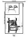
1
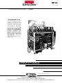
RETURN TO MAIN INDEX
Demo Zone
For use with equipment having “K” Number:
IM709
™
December, 2000
K1854-1
Safety Depends on You
Lincoln arc welding and cutting
equipment is designed and built
with safety in mind. However, your
overall safety can be increased by
proper installation ... and thoughtful operation on your part. DO
NOT INSTALL, OPERATE OR
REPAIR THIS EQUIPMENT
WITHOUT READING THIS
MANUAL AND THE SAFETY
PRECAUTIONS CONTAINED
THROUGHOUT. And, most
importantly, think before you act
and be careful.
OPERATOR’S MANUAL
Copyright © 2001 Lincoln Global Inc.
• World's Leader in Welding and Cutting Products •
• Sales and Service through Subsidiaries and Distributors Worldwide •
Cleveland, Ohio 44117-1199 U.S.A. TEL: 216.481.8100 FAX: 216.486.1751 WEB SITE: www.lincolnelectric.com
i
i
SAFETY
WARNING
CALIFORNIA PROPOSITION 65 WARNINGS
Diesel engine exhaust and some of its constituents
are known to the State of California to cause cancer, birth defects, and other reproductive harm.
The Above For Diesel Engines
The engine exhaust from this product contains
chemicals known to the State of California to cause
cancer, birth defects, or other reproductive harm.
The Above For Gasoline Engines
ARC WELDING CAN BE HAZARDOUS. PROTECT YOURSELF AND OTHERS FROM POSSIBLE SERIOUS INJURY OR DEATH.
KEEP CHILDREN AWAY. PACEMAKER WEARERS SHOULD CONSULT WITH THEIR DOCTOR BEFORE OPERATING.
Read and understand the following safety highlights. For additional safety information, it is strongly recommended that you
purchase a copy of “Safety in Welding & Cutting - ANSI Standard Z49.1” from the American Welding Society, P.O. Box
351040, Miami, Florida 33135 or CSA Standard W117.2-1974. A Free copy of “Arc Welding Safety” booklet E205 is available
from the Lincoln Electric Company, 22801 St. Clair Avenue, Cleveland, Ohio 44117-1199.
BE SURE THAT ALL INSTALLATION, OPERATION, MAINTENANCE AND REPAIR PROCEDURES ARE
PERFORMED ONLY BY QUALIFIED INDIVIDUALS.
FOR ENGINE
powered equipment.
1.h. To avoid scalding, do not remove the
radiator pressure cap when the engine is
hot.
1.a. Turn the engine off before troubleshooting and maintenance
work unless the maintenance work requires it to be running.
____________________________________________________
1.b. Operate engines in open, well-ventilated
areas or vent the engine exhaust fumes
outdoors.
____________________________________________________
1.c. Do not add the fuel near an open flame
welding arc or when the engine is running.
Stop the engine and allow it to cool before
refueling to prevent spilled fuel from vaporizing on contact with hot engine parts and
igniting. Do not spill fuel when filling tank. If
fuel is spilled, wipe it up and do not start
engine until fumes have been eliminated.
____________________________________________________
1.d. Keep all equipment safety guards, covers and devices in
position and in good repair.Keep hands, hair, clothing and
tools away from V-belts, gears, fans and all other moving
parts when starting, operating or repairing equipment.
____________________________________________________
1.e. In some cases it may be necessary to remove safety
guards to perform required maintenance. Remove
guards only when necessary and replace them when the
maintenance requiring their removal is complete.
Always use the greatest care when working near moving
parts.
___________________________________________________
1.f. Do not put your hands near the engine fan.
Do not attempt to override the governor or
idler by pushing on the throttle control rods
while the engine is running.
ELECTRIC AND
MAGNETIC FIELDS
may be dangerous
2.a. Electric current flowing through any conductor causes
localized Electric and Magnetic Fields (EMF). Welding
current creates EMF fields around welding cables and
welding machines
2.b. EMF fields may interfere with some pacemakers, and
welders having a pacemaker should consult their physician
before welding.
2.c. Exposure to EMF fields in welding may have other health
effects which are now not known.
2.d. All welders should use the following procedures in order to
minimize exposure to EMF fields from the welding circuit:
2.d.1. Route the electrode and work cables together - Secure
them with tape when possible.
2.d.2. Never coil the electrode lead around your body.
2.d.3. Do not place your body between the electrode and
work cables. If the electrode cable is on your right
side, the work cable should also be on your right side.
2.d.4. Connect the work cable to the workpiece as close as
possible to the area being welded.
___________________________________________________
1.g. To prevent accidentally starting gasoline engines while
turning the engine or welding generator during maintenance
work, disconnect the spark plug wires, distributor cap or
magneto wire as appropriate.
2.d.5. Do not work next to welding power source.
Mar ‘95
DEMO ZONE
ii
ii
SAFETY
ARC RAYS can burn.
ELECTRIC SHOCK can
kill.
3.a. The electrode and work (or ground) circuits
are electrically “hot” when the welder is on.
Do not touch these “hot” parts with your bare
skin or wet clothing. Wear dry, hole-free
gloves to insulate hands.
3.b. Insulate yourself from work and ground using dry insulation.
Make certain the insulation is large enough to cover your full
area of physical contact with work and ground.
In addition to the normal safety precautions, if welding
must be performed under electrically hazardous
conditions (in damp locations or while wearing wet
clothing; on metal structures such as floors, gratings or
scaffolds; when in cramped positions such as sitting,
kneeling or lying, if there is a high risk of unavoidable or
accidental contact with the workpiece or ground) use
the following equipment:
• Semiautomatic DC Constant Voltage (Wire) Welder.
• DC Manual (Stick) Welder.
• AC Welder with Reduced Voltage Control.
4.a. Use a shield with the proper filter and cover
plates to protect your eyes from sparks and
the rays of the arc when welding or observing
open arc welding. Headshield and filter lens
should conform to ANSI Z87. I standards.
4.b. Use suitable clothing made from durable flame-resistant
material to protect your skin and that of your helpers from
the arc rays.
4.c. Protect other nearby personnel with suitable, non-flammable
screening and/or warn them not to watch the arc nor expose
themselves to the arc rays or to hot spatter or metal.
FUMES AND GASES
can be dangerous.
5.a. Welding may produce fumes and gases
hazardous to health. Avoid breathing these
fumes and gases.When welding, keep
your head out of the fume. Use enough
ventilation and/or exhaust at the arc to keep
fumes and gases away from the breathing zone. When
welding with electrodes which require special
ventilation such as stainless or hard facing (see
instructions on container or MSDS) or on lead or
cadmium plated steel and other metals or coatings
which produce highly toxic fumes, keep exposure as
low as possible and below Threshold Limit Values (TLV)
using local exhaust or mechanical ventilation. In
confined spaces or in some circumstances, outdoors, a
respirator may be required. Additional precautions are
also required when welding on galvanized steel.
3.c. In semiautomatic or automatic wire welding, the electrode,
electrode reel, welding head, nozzle or semiautomatic
welding gun are also electrically “hot”.
3.d. Always be sure the work cable makes a good electrical
connection with the metal being welded. The connection
should be as close as possible to the area being welded.
3.e. Ground the work or metal to be welded to a good electrical
(earth) ground.
3.f. Maintain the electrode holder, work clamp, welding cable and
welding machine in good, safe operating condition. Replace
damaged insulation.
3.g. Never dip the electrode in water for cooling.
3.h. Never simultaneously touch electrically “hot” parts of
electrode holders connected to two welders because voltage
between the two can be the total of the open circuit voltage
of both welders.
3.i. When working above floor level, use a safety belt to protect
yourself from a fall should you get a shock.
3.j. Also see Items 6.c. and 8.
5.b. Do not weld in locations near chlorinated hydrocarbon vapors
coming from degreasing, cleaning or spraying operations.
The heat and rays of the arc can react with solvent vapors to
form phosgene, a highly toxic gas, and other irritating products.
5.c. Shielding gases used for arc welding can displace air and
cause injury or death. Always use enough ventilation,
especially in confined areas, to insure breathing air is safe.
5.d. Read and understand the manufacturer’s instructions for this
equipment and the consumables to be used, including the
material safety data sheet (MSDS) and follow your
employer’s safety practices. MSDS forms are available from
your welding distributor or from the manufacturer.
5.e. Also see item 1.b.
Mar ‘95
DEMO ZONE
iii
iii
SAFETY
WELDING SPARKS can
cause fire or explosion.
CYLINDER may explode
if damaged.
6.a. Remove fire hazards from the welding area.
If this is not possible, cover them to prevent
the welding sparks from starting a fire.
Remember that welding sparks and hot
materials from welding can easily go through small cracks
and openings to adjacent areas. Avoid welding near
hydraulic lines. Have a fire extinguisher readily available.
6.b. Where compressed gases are to be used at the job site,
special precautions should be used to prevent hazardous
situations. Refer to “Safety in Welding and Cutting” (ANSI
Standard Z49.1) and the operating information for the
equipment being used.
7.a. Use only compressed gas cylinders
containing the correct shielding gas for the
process used and properly operating
regulators designed for the gas and
pressure used. All hoses, fittings, etc. should be suitable for
the application and maintained in good condition.
7.b. Always keep cylinders in an upright position securely
chained to an undercarriage or fixed support.
7.c. Cylinders should be located:
• Away from areas where they may be struck or subjected to
physical damage.
6.c. When not welding, make certain no part of the electrode
circuit is touching the work or ground. Accidental contact
can cause overheating and create a fire hazard.
6.d. Do not heat, cut or weld tanks, drums or containers until the
proper steps have been taken to insure that such procedures
will not cause flammable or toxic vapors from substances
inside. They can cause an explosion even though they have
been “cleaned”. For information, purchase “Recommended
Safe Practices for the Preparation for Welding and Cutting of
Containers and Piping That Have Held Hazardous
Substances”, AWS F4.1 from the American Welding Society
(see address above).
6.e. Vent hollow castings or containers before heating, cutting or
welding. They may explode.
6.f. Sparks and spatter are thrown from the welding arc. Wear oil
free protective garments such as leather gloves, heavy shirt,
cuffless trousers, high shoes and a cap over your hair. Wear
ear plugs when welding out of position or in confined places.
Always wear safety glasses with side shields when in a
welding area.
6.g. Connect the work cable to the work as close to the welding
area as practical. Work cables connected to the building
framework or other locations away from the welding area
increase the possibility of the welding current passing
through lifting chains, crane cables or other alternate circuits. This can create fire hazards or overheat lifting chains
or cables until they fail.
6.h. Also see item 1.c.
• A safe distance from arc welding or cutting operations and
any other source of heat, sparks, or flame.
7.d. Never allow the electrode, electrode holder or any other
electrically “hot” parts to touch a cylinder.
7.e. Keep your head and face away from the cylinder valve outlet
when opening the cylinder valve.
7.f. Valve protection caps should always be in place and hand
tight except when the cylinder is in use or connected for
use.
7.g. Read and follow the instructions on compressed gas
cylinders, associated equipment, and CGA publication P-l,
“Precautions for Safe Handling of Compressed Gases in
Cylinders,” available from the Compressed Gas Association
1235 Jefferson Davis Highway, Arlington, VA 22202.
FOR ELECTRICALLY
powered equipment.
8.a. Turn off input power using the disconnect
switch at the fuse box before working on
the equipment.
8.b. Install equipment in accordance with the U.S. National
Electrical Code, all local codes and the manufacturer’s
recommendations.
8.c. Ground the equipment in accordance with the U.S. National
Electrical Code and the manufacturer’s recommendations.
Mar ‘95
DEMO ZONE
iv
SAFETY
iv
zones où l’on pique le laitier.
PRÉCAUTIONS DE SÛRETÉ
Pour votre propre protection lire et observer toutes les instructions
et les précautions de sûreté specifiques qui parraissent dans ce
manuel aussi bien que les précautions de sûreté générales suivantes:
Sûreté Pour Soudage A L’Arc
1. Protegez-vous contre la secousse électrique:
a. Les circuits à l’électrode et à la piéce sont sous tension
quand la machine à souder est en marche. Eviter toujours
tout contact entre les parties sous tension et la peau nue
ou les vétements mouillés. Porter des gants secs et sans
trous pour isoler les mains.
b. Faire trés attention de bien s’isoler de la masse quand on
soude dans des endroits humides, ou sur un plancher
metallique ou des grilles metalliques, principalement dans
les positions assis ou couché pour lesquelles une grande
partie du corps peut être en contact avec la masse.
c. Maintenir le porte-électrode, la pince de masse, le câble
de soudage et la machine à souder en bon et sûr état
defonctionnement.
d.Ne jamais plonger le porte-électrode dans l’eau pour le
refroidir.
e. Ne jamais toucher simultanément les parties sous tension
des porte-électrodes connectés à deux machines à souder
parce que la tension entre les deux pinces peut être le
total de la tension à vide des deux machines.
f. Si on utilise la machine à souder comme une source de
courant pour soudage semi-automatique, ces precautions
pour le porte-électrode s’applicuent aussi au pistolet de
soudage.
2. Dans le cas de travail au dessus du niveau du sol, se protéger
contre les chutes dans le cas ou on recoit un choc. Ne jamais
enrouler le câble-électrode autour de n’importe quelle partie
du corps.
3. Un coup d’arc peut être plus sévère qu’un coup de soliel,
donc:
a. Utiliser un bon masque avec un verre filtrant approprié
ainsi qu’un verre blanc afin de se protéger les yeux du rayonnement de l’arc et des projections quand on soude ou
quand on regarde l’arc.
b. Porter des vêtements convenables afin de protéger la
peau de soudeur et des aides contre le rayonnement de
l‘arc.
c. Protéger l’autre personnel travaillant à proximité au
soudage à l’aide d’écrans appropriés et non-inflammables.
4. Des gouttes de laitier en fusion sont émises de l’arc de
soudage. Se protéger avec des vêtements de protection libres
de l’huile, tels que les gants en cuir, chemise épaisse, pantalons sans revers, et chaussures montantes.
5. Toujours porter des lunettes de sécurité dans la zone de
soudage. Utiliser des lunettes avec écrans lateraux dans les
6. Eloigner les matériaux inflammables ou les recouvrir afin de
prévenir tout risque d’incendie dû aux étincelles.
7. Quand on ne soude pas, poser la pince à une endroit isolé de
la masse. Un court-circuit accidental peut provoquer un
échauffement et un risque d’incendie.
8. S’assurer que la masse est connectée le plus prés possible
de la zone de travail qu’il est pratique de le faire. Si on place
la masse sur la charpente de la construction ou d’autres
endroits éloignés de la zone de travail, on augmente le risque
de voir passer le courant de soudage par les chaines de levage, câbles de grue, ou autres circuits. Cela peut provoquer
des risques d’incendie ou d’echauffement des chaines et des
câbles jusqu’à ce qu’ils se rompent.
9. Assurer une ventilation suffisante dans la zone de soudage.
Ceci est particuliérement important pour le soudage de tôles
galvanisées plombées, ou cadmiées ou tout autre métal qui
produit des fumeés toxiques.
10. Ne pas souder en présence de vapeurs de chlore provenant
d’opérations de dégraissage, nettoyage ou pistolage. La
chaleur ou les rayons de l’arc peuvent réagir avec les vapeurs
du solvant pour produire du phosgéne (gas fortement toxique)
ou autres produits irritants.
11. Pour obtenir de plus amples renseignements sur la sûreté,
voir le code “Code for safety in welding and cutting” CSA
Standard W 117.2-1974.
PRÉCAUTIONS DE SÛRETÉ POUR
LES MACHINES À SOUDER À
TRANSFORMATEUR ET À
REDRESSEUR
1. Relier à la terre le chassis du poste conformement au code de
l’électricité et aux recommendations du fabricant. Le dispositif
de montage ou la piece à souder doit être branché à une
bonne mise à la terre.
2. Autant que possible, I’installation et l’entretien du poste seront
effectués par un électricien qualifié.
3. Avant de faires des travaux à l’interieur de poste, la debrancher à l’interrupteur à la boite de fusibles.
4. Garder tous les couvercles et dispositifs de sûreté à leur
place.
Mar. ‘93
DEMO ZONE
v
v
Thank You
for selecting a QUALITY product by Lincoln Electric. We want you
to take pride in operating this Lincoln Electric Company product
••• as much pride as we have in bringing this product to you!
Please Examine Carton and Equipment For Damage Immediately
When this equipment is shipped, title passes to the purchaser upon receipt by the carrier. Consequently, Claims
for material damaged in shipment must be made by the purchaser against the transportation company at the
time the shipment is received.
Please refer to Individual machine Operator’s Manuals for Parts Order information.
Read this Operators Manual and any others included with this equipment completely before attempting to
use this equipment. Save this manual and keep it handy for quick reference. Pay particular attention to the safety
instructions we have provided for your protection. The level of seriousness to be applied to each is explained
below:
WARNING
This statement appears where the information must be followed exactly to avoid serious personal injury or
loss of life.
CAUTION
This statement appears where the information must be followed to avoid minor personal injury or damage to
this equipment.
vi
TABLE OF CONTENTS
Page
Installation.......................................................................................................................Section A
Technical Specifications .......................................................................................................A-1
Safety Precautions. ..............................................................................................................A-2
Input and Grounding Connections........................................................................................A-2
Input Power ...................................................................................................................A-2
Grounding .....................................................................................................................A-2
Output Cables, Connections and Limitations .......................................................................A-2
Electrode and Work Cable Connections .......................................................................A-2
Installation of Field Installed Options....................................................................................A-3
Caster Wheels...............................................................................................................A-3
Installation of Equipment Required for Recommended Processes ......................................A-3
General Installation Requirements .......................................................................................A-4
Location.........................................................................................................................A-4
Engine Exhaust .............................................................................................................A-4
Welding Smoke and Fume ............................................................................................A-4
Stacking ........................................................................................................................A-4
Handling ........................................................................................................................A-4
Operation.........................................................................................................................Section B
Safety Precautions. ..............................................................................................................B-1
General Description..............................................................................................................B-1
Demo Zone ...................................................................................................................B-1
Recommended Processes and Equipment ..........................................................................B-1
Recommended Processes ............................................................................................B-1
Process Limitations .......................................................................................................B-1
Recommended Equipment / Interface ..................................................................................B-2
Equipment Limitations ...................................................................................................B-2
Design Features ...................................................................................................................B-2
Platform Commonalities ................................................................................................B-2
Operational Controls and Features of the Demo Zone .................................................B-2
Circuit Breaker ..............................................................................................................B-2
Regulatory Requirements.....................................................................................................B-2
Operating Instructions ..........................................................................................................B-2
Additional Safety Precautions ..............................................................................................B-2
Welding and Cutting Area .............................................................................................B-2
Gas Cylinders................................................................................................................B-2
Power Sources ..............................................................................................................B-2
Welder Operation .................................................................................................................B-3
Duty Cycle .....................................................................................................................B-3
Auxiliary Power Operation ....................................................................................................B-3
Accessories .....................................................................................................Section C
Factory Installed Options / Accessories ................................................................C-1
Field Installed Options / Accessories.....................................................................C-1
Caster Wheels ................................................................................................C-1
Maintenance ....................................................................................................Section D
Safety Precautions ................................................................................................D-1
Routine Maintenance.............................................................................................D-1
Periodic Maintenance ............................................................................................D-1
Troubleshooting ..............................................................................................Section E
Diagrams ..........................................................................................................Section F
Wiring Diagram.......................................................................................................F-1
________________________________________________________________________
A-1
A-1
INSTALLATION
TECHNICAL SPECIFICATIONS - Demo Zone (K-1854-1)
ELECTRICAL INPUT REQUIREMENTS
Voltage Specification
Input Connection
Specification
230 VAC single phase, 40 amps
Type 6-50P plug
RATED OUTPUT
The Demo Zone is intended for display and demonstration use. It is intended for light duty operation.
The Demo Zone operator must observe the 40 amp input current limitation. Because of the input power
limitation, power sources (except Ranger 250) when used at maximum output must be operated at low
duty cycles. Refer to Welder Operation - Duty Cycle section of this manual.
PHYSICAL DIMENSIONS
HEIGHT
WIDTH
DEPTH
WEIGHT
53.00 in.
66.00 in.
53.00 in.
1346.2 mm
1676.4 mm
1346.2 mm
1707 lbs. (w/o gas cylinders)
2467 lbs. (with gas cylinders)
774.3 kg. (w/o gas cylinders)
1119.0 kg. (with gas cylinders)
DEMO ZONE
A-2
A-2
INSTALLATION
SAFETY PRECAUTIONS
INPUT AND GROUNDING CONNECTIONS
WARNING
INPUT POWER
ELECTRIC SHOCK can kill.
• Only qualified personnel should
perform this installation.
The Demo Zone is designed to operate from 230 volt,
60 Hz single-phase input power with 40-amp capacity.
A 6-50R type receptacle must be provided by the
user. The receptacle must be installed by a qualified
person and must be in accordance with applicable
local and national electrical codes.
• Turn the input power OFF at the
circuit breaker or fuse box
before working on this
equipment.
• Do not touch electrically hot
parts.
• Always connect the Demo Zone to a power
supply grounded per the National Electrical
Code and any local codes.
• This demonstration rack is intended for
indoor use and display only.
• Shelter or protect from rain, moisture and
condensation.
• Do not operate electric equipment when
wet.
The lighting system requires 120 volt 60 Hz power.
Plug the line cord into a conventional 120 volt receptacle for lighting operation. The lighting system is for
display and convenience purposes.
The Input Plugs for the Demo Zone are connected at the
factory.
GROUNDING
CAUTION
CYLINDERS could explode
if damaged.
• Keep cylinders upright and
secured to a support.
• Keep cylinders away from areas
where they could be damaged.
• Never allow the electrodes or torches to touch
the cylinders.
• Keep cylinders away from live electrical circuits.
• Maximum inlet pressures must be observed.
-----------------------------------------------------------------------FALLING EQUIPMENT can cause
injury.
• Do not lift with gas cylinder in place.
• Do not trailer or transport over the
road
-----------------------------------------------------------------------ENGINE EXHAUST can kill.
• Use in open, well ventilated areas or
vent exhaust outside
------------------------------------------------------------------------
When the Demo Zone is connected to a conventional
power distribution system, the frame of the Demo
Zone must be grounded. The input cable provided
with the Demo Zone contains a grounding conductor.
Additionally, another ground lead must be connected.
Connect the frame of the Demo Zone to a good electrical ground using the #1 AWG lead included with the
Demo Zone. The purpose of this additional ground is
to minimize disturbance of the high frequency unit and
to provide a path for stray welding currents.
Some applications may not use conventional input
power and instead utilize the generating capability of
the Ranger 250 for power. In this case, the ground
lead is required only if the high frequency unit of the
Square Wave TIG 175 is used.
OUTPUT CABLES AND
CONNECTIONS
ELECTRODE AND WORK CABLE CONNECTIONS
The Demo Zone is supplied with the output cables
connected at the power sources for positive electrode
polarity. To change the polarity of a power source,
switch the cables at the output terminals of the power
source, or change the power source polarity switch as
applicable.
A bolted work lead runs from the work buss connection of the Demo Zone to the work table. The work
table connection must be firm and secure.
DEMO ZONE
A-3
INSTALLATION
INSTALLATION OF FIELD INSTALLED
OPTIONS
CASTER WHEELS (PART OF K1848-1)
Caster wheels, which are provided, can be installed
by lifting the Demo Zone approximately eight inches
above ground level. Use the mounting hardware supplied to fasten the caster wheel to the mounting plate.
Tighten all fasteners.
INSTALLATION OF EQUIPMENT
REQUIRED FOR RECOMMENDED
PROCESSES
A-3
6. BEFORE the gas cylinders are installed, measure
the cable length needed for the spool gun (it is routed the same way as the Power MIG gun) and coil
the rest, wire tie it and store it underneath the
bench between the Ranger and Power MIG.
7. BEFORE the gas cylinders are installed, connect
the battery in the Ranger 250.
8. Gas cylinder covers will improve the appearance of
your unit. When used, put the covers on before
installing the cylinder.
9. Place the cylinders in the Demo Zone. The cylinders can be installed by using the rear or side
openings, or a combination of both.
1. As shipped from the factory, two diagonal braces
are bolted to either side of the Demo Zone. The
braces are approximately 62" in length.
• Remove the brace on the tool box side of the Demo Zone
• Do not remove the brace located on the Ranger
250 side of the Demo Zone.
When using the rear frame opening, move the upper
and lower support bars out of way. Install the cylinders and replace the support bars to the closed
position.
2. The Demo Zone is made for ease of set up. Drive
rolls are installed and liners are in the guns.
When using side frame opening, lift brace and swing
out of the way. Install the cylinders and swing brace
back into position, push brace down through locking
tube to secure.
3. A Harris Kit, containing gas components, is included with the Demo Zone. Some details about the kit:
• The double flow meter-regulator is for the argon
gas cylinder. A "Y" fitting is also used on one of the
flow meter outlets. The argon is fed to the Spool
Gun, The Square Wave TIG 175 and the two-piece
TIG torch attached to the Ranger 250.
• The other regulator is provided for the 75/25
argon/CO2 gas cylinder. Connect a "Y" fitting to this
regulator. The Power MIG and LN25 is fed from the
"Y" fitting. Use hoses with inert gas fittings. The
short hose is used with the LN7.
• The oxygen fitting (with 1/4 inch pipe thread) is for
use with the Pro-Cut gas hose. Use the short oxygen hose between the Pro-Cut and regulator.
4. Two plasma torches are provided with the Demo
Zone. Use the short length plasma torch with the
Demo Zone. The torch with the long length is not
recommended because the length is inconvenient
when used with the Demo Zone. Store the long
plasma torch. Use the long torch if the Pro Cut is
removed from the Demo Zone.
Place the air cylinder directly in back of the Pro Cut.
Place the argon cylinder next to the air cylinder.
10. Install the optional casters. This is easily done
after placing cylinders in Demo Zone, as the
height of the Demo Zone is higher with the wheels
installed.
11. Set up the two TIG torches provided. The TIG
torch that comes with the SW175 is used on both
AC and DC. A recommendation is to use a point at
one end of the tungsten and a ball at the other
end.
12. The welding table must exposed before demonstrating. Pull the table to the open position when in
use. The table can be pushed back in, out of the
way, when the table is not in use. Since the table
has a bolted work lead permanently attached, no
work clamp is necessary for welding or cutting
operations.
5. BEFORE the gas cylinders are installed, run the
gun for the Power MIG from the back of the rack
through the bench (under) and then up to the
Power MIG. This gun will run along the back of the
Square Wave TIG 175 and then to a gun holder. It
should be long enough to reach the worktable and
this helps keep the cables from getting tangled.
DEMO ZONE
A-4
A-4
INSTALLATION
GENERAL INSTALLATION REQUIREMENTS
HANDLING
LOCATION
A pallet jack or forklift truck can be used to move the
Demo Zone and to install the caster kit. The placement of the pallet jack or forks must balance the
Demo Zone load to prevent tipping.
Locate the Demo Zone on a flat surface. The Demo
Zone is intended for indoor use only. The Demo Zone
must be sheltered from rain and water.
WARNING
ENGINE EXHAUST
FALLING EQUIPMENT can cause
injury.
CAUTION
Provide an exhaust capability for the Ranger 250
machine. Flexible metal exhaust hose, available
from automobile parts stores, should be used to
exhaust gasses to the outdoors. The exhaust pipe
on the Ranger 250 is 1.5" diameter nominal. Use a
clamp at the muffler to ensure a good seal.
The exhaust pipe and flexible metal exhaust hose
is hot! Do not touch when hot. Keep flammable
material away from the exhaust hose. Place a "Hot
- Do not touch" sign near the hose to warn of the
hazard.
Ensure that there is sufficient fresh air and ventilation available during operation of the Ranger
250.
• Do not lift the Demo Zone by overhead crane.
• Do not lift the Demo Zone with gas
cylinder in place.
• Lift from front of Demo Zone only.
Do not lift from left, right or rear
sides.
The Demo Zone is too heavy for one person to
move by hand on an inclined surface. Avoid situations that may injure yourself or others.
WELDING SMOKE AND FUME
Provide an exhaust for welding smoke and fume.
STACKING
The Demo Zone is not designed for stacking.
DEMO ZONE
B-1
OPERATION
SAFETY PRECAUTIONS
GENERAL DESCRIPTION
Read and understand this entire section before operating the machine.
DEMO ZONE
B-1
The Demo Zone is a compact system to display and
demonstrate welding and cutting equipment.
WARNING
The Demo Zone contains:
ELECTRIC SHOCK
can kill.
- Square Wave TIG 175 Power Source
• Do not touch electrically live parts or
electrode with skin or wet clothing.
- Power MIG 255 Power Source
- Ranger 250 Power Source
• Insulate yourself from work and ground.
- V350 Pro Power Source
• Always wear dry insulating gloves.
- Pro Cut 55 Plasma Cutter
• Read and follow “Electric Shock Warnings”
in the Safety section if welding must be
performed under electrically hazardous
conditions such as welding in wet areas or
on or in the workpiece.
- LN-25 Wire Feeder
- LN-7GMA Wire Feeder
- Holder for 4 gas cylinders
- Welding table
FUMES AND GASES
can be dangerous.
- Power distribution system with circuit breaker protection
• Keep your head out of fumes.
- Welding cables and torches
• Use ventilation or exhaust to
remove fumes from breathing
zone.
- Tool box for storage of tools, welding accessories
and welding plates
- Illuminated lower area by neon and florescent lamps
WELDING SPARKS
can cause fire or
explosion
- Prominent promotional sign
- Caster wheels allow easy movement.
• Keep flammable material away.
• Do not weld on containers that
have held combustibles.
All equipment on the Demo Zone is connected and
ready to weld. The Demo Zone obtains its power from
a 230V 40A receptacle.
ARC RAYS
can burn.
RECOMMENDED PROCESSES AND
EQUIPMENT
• Wear eye, ear and body
protection.
RECOMMENDED PROCESSES
Observe additional Safety Guidelines detailed in
the beginning of this manual.
The Demo Zone is capable of demonstrating MIG,
TIG, SMAW, CAC and plasma cutting.
PROCESS LIMITATIONS
– determined by individual equipment
DEMO ZONE
B-2
B-2
OPERATION
RECOMMENDED EQUIPMENT /
INTERFACE
ADDITIONAL SAFETY PRECAUTIONS
WELDING AND CUTTING AREA
EQUIPMENT LIMITATIONS
WARNING
The Demo Zone is intended for indoor display and
demonstration use. The Demo Zone is intended for
light duty operation. Because of the input power limitation, power sources (except Ranger 250) may only be
used at maximum output with low duty cycles. (Refer
to Welder Operation-Duty Cycle section of this manual).
Welding and Cutting must take place only on the
welding table provided with the Demo Zone. Do not
weld or cut on objects away from the Demo Zone
welding table. Do not weld on the frame of the Demo
Zone.
The Demo zone is not intended for road transportation
or to be hauled on a trailer.
Direct sparks away from welding machines, especially
the fuel fill area of the Ranger 250.
WARNING
The Demo zone must not be lifted with gas cylinders
in place.
CYLINDERS could explode
if damaged.
DESIGN FEATURES
•Keep cylinders upright and secured to
a support.
PLATFORM COMMONALTIES
The Demo Zone utilizes standard power source and
wire feeder configurations. Output cables and torches
are modified in length for use with the Demo Zone.
• Keep cylinders away from areas where they could
be damaged.
• Never allow the electrodes or torches to touch the
cylinders.
OPERATIONAL CONTROLS AND
FEATURES OF THE DEMO ZONE
• Keep cylinders away from live electrical circuits.
Refer to the individual Operator’s Manuals for equipment included in the Demo Zone.
• Maximum inlet pressures must be observed.
CIRCUIT BREAKER
• Do not lift Demo Zone with gas cylinders in place.
The 230V input power to the Demo Zone is controlled
by a 40-amp circuit breaker located on the rear of the
Demo Zone.
REGULATORY REQUIREMENTS
The power source and wire feed equipment included
with the Demo Zone are individually listed or certified
to CSA or UL agencies.
OPERATING INSTRUCTIONS
Read and understand the Operator’s Manuals for
all of the equipment contained in the Demo Zone.
The operating instructions for each equipment
type are not repeated here in the Demo Zone manual.
Plug the Demo Zone into a 230 volt 40 amp receptacle. Locate the circuit breaker at the rear of the Demo
Zone and switch it on. Plug the lighting system into a
120 volt receptacle. Switch the power for individual
machines on as required for demonstration purposes.
• Do not strike an arc on any gas cylinders. Never
allow the electrode, electrode holder or any other
electrically "hot" parts to touch a cylinder.
• Gas cylinders must be securely fastened to the
Demo Zone frame. Chains are supplied and are
attached to the frame.
• When caster wheels are installed, block the
Demo Zone from movement when removing or
installing gas clinders.
POWER SOURCES
The Demo Zone is a flexible system capable of
demonstrating many varied processes. The set-up of
equipment may require polarity changes, torch
changes or electrode changes. Turn-off the welding
power source or plasma cutter when changing or connecting output cables torches or electrodes.
DEMO ZONE
B-3
OPERATION
WELDER OPERATION
DUTY CYCLE
Full output and duty cycle may not be obtained from
all power sources. The output and duty cycle may be
limited by the 40 amp input power limitation of the
Demo Zone. The duty cycle of the power source must
be adjusted to be within the capability of the 40 amp
input supply.
Duty cycle is based upon a ten minute period. A 10%
duty cycle represents 1 minute of welding and 9 minutes of idling in a ten minute period.
Some examples of allowable duty cycles of the Demo
Zone are given. If the duty cycle or input currents
exceed the capability of the 40 amp circuit breaker,
the breaker will trip off. For lower output currents, the
duty cycle is extended from what is listed.
V350-PRO
200A at 28v
275A at 31V
100% duty cycle
10% duty cycle
41A input
62A input
Power MIG 255 (machine limited)
200A at 28v
250A at 30v
60% duty cycle
40% duty cycle
37A input
46A input
15% duty cycle
55A input
Pro Cut 55
55A
Square Wave TIG 175
150A
10% duty cycle
65A input
AUXILIARY POWER OPERATION
Duty cycle and maximum current may be less than
rated value if the power sources are powered from the
Ranger 250.
(Refer to Ranger 250 Operator’s Manual).
DEMO ZONE
B-3
C-1
FACTORY INSTALLED
ACCESSORIES
C-1
ACCESSORIES
OPTIONS
/
FIELD
INSTALLED
ACCESSORIES
OPTIONS
/
- none
CASTER WHEELS
Caster wheels, which are provided, are a field
installed option for the Demo Zone. The 5-inch diameter caster wheels offer high mobility for in-shop use.
DEMO ZONE
D-1
MAINTENANCE
D-1
ROUTINE MAINTENANCE
SAFETY PRECAUTIONS
Refer to individual Operator’s Manuals for routine
maintenance requirements.
WARNING
ELECTRIC SHOCK can kill.
Perform the following daily routine:
• Turn the input power OFF at the
disconnect switchs or fuse boxes
before working on all equipment.
• Check that no combustible materials are in the welding or cutting area or around the machine.
• Do not touch electrically hot parts.
• Remove any debris, dust, dirt, or materials that could
block the air flow to the machines for cooling.
• Have qualified personnel do all maintenance
and troubleshooting work.
PERIODIC MAINTENANCE
• Turn engine or welders off before working
inside the machines or servicing the engine.
Refer to individual Operator’s Manuals for periodic
maintenance requirements.
• Observe all safety precautions in the individual
machine Operator’s Manuals as well as this manual.
Perform the following periodically:
• Inspect the welding cables, torches and electrode
holders for any slits or punctures in the cable jacket,
or any condition that would affect the proper operation.
• Inspect gas hoses and regulators.
• Inspect gas cylinder chains and fasteners.
• The weld table is insulated from the Demo Zone
frame. Inspect the weld table mechanism to ensure
that the insulation system is intact.
DEMO ZONE
E-1
TROUBLESHOOTING
E-1
WARNING
Service and Repair should only be performed by Lincoln Electric Factory Trained Personnel.
Unauthorized repairs performed on this equipment may result in danger to the technician and
machine operator. For your safety and to avoid Electrical Shock, please observe all safety
notes and precautions detailed throughout this and individual machine Operator’s Manuals.
Consult individual machine Operator’s Manuals for detailed troubleshooting of specific
machines.
__________________________________________________________________________
CAUTION
If for any reason you do not understand the test procedures or are unable to perform the tests/repairs safely, contact your
Local Lincoln Authorized Field Service Facility for technical troubleshooting assistance before you proceed.
DEMO ZONE
DEMO ZONE
WBG
40A 40A
230 VOLT INPUT
LEAD COLOR CODE:
B = BLACK
W = WHITE
G = GREEN
50 AMP
RECEPTACLE
50 AMP
RECEPTACLE
50 AMP
RECEPTACLE
N.A. BOX BONDED TO GROUND
NOTES:
N.A.
50 AMP
RECEPTACLE
TO GROUND PER
NATIONAL ELECTRIC CODE
MATERIAL: WIRE 8 AWG TYPE OR THHN OR THWN OR GAS AND OIL RESISTANT 600 V (UL)
230V INPUT CIRCUIT
TO POWER SOURCE
WORK TERMINAL
4700 OHM
5W
LOWER
COPPER BAR
4700 OHM
5W
UPPER
COPPER BAR
WORK CIRCUIT
TO POWER SOURCE
WORK TERMINAL
DEMO ZONE WIRING DIAGRAM
M19808
10-2000
15uF
250 V
15uF
250 V
TO WELDING
TAB LE
F-1
DIAGRAMS
F-1
NOTES
DEMO ZONE
● Do not touch electrically live parts or
WARNING
Spanish
AVISO DE
PRECAUCION
French
ATTENTION
German
WARNUNG
Portuguese
ATENÇÃO
● Keep flammable materials away.
● Wear eye, ear and body protection.
● Mantenga el material combustible
● Protéjase los ojos, los oídos y el
electrode with skin or wet clothing.
● Insulate yourself from work and
ground.
● No toque las partes o los electrodos
bajo carga con la piel o ropa mojada.
● Aislese del trabajo y de la tierra.
● Ne laissez ni la peau ni des vête-
ments mouillés entrer en contact
avec des pièces sous tension.
● Isolez-vous du travail et de la terre.
● Berühren Sie keine stromführenden
Teile oder Elektroden mit Ihrem
Körper oder feuchter Kleidung!
● Isolieren Sie sich von den
Elektroden und dem Erdboden!
● Não toque partes elétricas e elec-
trodos com a pele ou roupa molhada.
● Isole-se da peça e terra.
fuera del área de trabajo.
● Gardez à l’écart de tout matériel
inflammable.
● Entfernen Sie brennbarres Material!
cuerpo.
● Protégez vos yeux, vos oreilles et
votre corps.
● Tragen Sie Augen-, Ohren- und Kör-
perschutz!
● Mantenha inflamáveis bem guarda-
dos.
● Use proteção para a vista, ouvido e
corpo.
Japanese
Chinese
Korean
Arabic
READ AND UNDERSTAND THE MANUFACTURER’S INSTRUCTION FOR THIS EQUIPMENT AND THE CONSUMABLES TO BE
USED AND FOLLOW YOUR EMPLOYER’S SAFETY PRACTICES.
SE RECOMIENDA LEER Y ENTENDER LAS INSTRUCCIONES DEL FABRICANTE PARA EL USO DE ESTE EQUIPO Y LOS
CONSUMIBLES QUE VA A UTILIZAR, SIGA LAS MEDIDAS DE SEGURIDAD DE SU SUPERVISOR.
LISEZ ET COMPRENEZ LES INSTRUCTIONS DU FABRICANT EN CE QUI REGARDE CET EQUIPMENT ET LES PRODUITS A
ETRE EMPLOYES ET SUIVEZ LES PROCEDURES DE SECURITE DE VOTRE EMPLOYEUR.
LESEN SIE UND BEFOLGEN SIE DIE BETRIEBSANLEITUNG DER ANLAGE UND DEN ELEKTRODENEINSATZ DES HERSTELLERS. DIE UNFALLVERHÜTUNGSVORSCHRIFTEN DES ARBEITGEBERS SIND EBENFALLS ZU BEACHTEN.
● Keep your head out of fumes.
● Use ventilation or exhaust to
● Turn power off before servicing.
● Do not operate with panel open or
guards off.
remove fumes from breathing zone.
● Los humos fuera de la zona de res-
piración.
● Mantenga la cabeza fuera de los
humos. Utilice ventilación o
aspiración para gases.
● Gardez la tête à l’écart des fumées.
● Utilisez un ventilateur ou un aspira-
● Desconectar el cable de ali-
mentación de poder de la máquina
antes de iniciar cualquier servicio.
● Débranchez le courant avant l’entre-
tien.
teur pour ôter les fumées des zones
de travail.
● Vermeiden Sie das Einatmen von
Schweibrauch!
● Sorgen Sie für gute Be- und
Entlüftung des Arbeitsplatzes!
● Mantenha seu rosto da fumaça.
● Use ventilação e exhaustão para
remover fumo da zona respiratória.
● Strom vor Wartungsarbeiten
● No operar con panel abierto o
guardas quitadas.
● N’opérez pas avec les panneaux
ouverts ou avec les dispositifs de
protection enlevés.
● Anlage nie ohne Schutzgehäuse
abschalten! (Netzstrom völlig öffnen; Maschine anhalten!)
oder Innenschutzverkleidung in
Betrieb setzen!
● Não opere com as tampas removidas.
● Desligue a corrente antes de fazer
● Mantenha-se afastado das partes
serviço.
● Não toque as partes elétricas nuas.
● Não opere com os paineis abertos
moventes.
WARNING
Spanish
AVISO DE
PRECAUCION
French
ATTENTION
German
WARNUNG
Portuguese
ATENÇÃO
ou guardas removidas.
Japanese
Chinese
Korean
Arabic
LEIA E COMPREENDA AS INSTRUÇÕES DO FABRICANTE PARA ESTE EQUIPAMENTO E AS PARTES DE USO, E SIGA AS
PRÁTICAS DE SEGURANÇA DO EMPREGADOR.
• World's Leader in Welding and Cutting Products •
• Sales and Service through Subsidiaries and Distributors Worldwide •
Cleveland, Ohio 44117-1199 U.S.A. TEL: 216.481.8100 FAX: 216.486.1751 WEB SITE: www.lincolnelectric.com