1
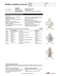
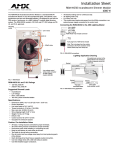
MULTISET/MULTISET PRO - MSCR/MHCR
Installation and
Operation
MULTISET/MULTISET PRO - CHANNEL REMOTE
INSTALLATION AND
OPERATIONS
MANUAL
Specifications
Onset Micro-Touch Digital Multi-Location Remote
Voltage: 108 - 132 VAC 60 Hz.
Output Current: 2.5 ma.
Models: Low wattage - MSCR
High Wattage - MHCR
Operating Temperature: 0 to 40˚ C
Dimensions:
MS Models
MH Models
H
4”
4-1/2”
W
1-11/16’
2-9/16’
D
1-7/8’
1-7/8’
Wt. (oz)
4.0
5.0
Colors:
MS Models:
White, Ivory
MH Models:
White
* Black, Grey and Almond are custom colors, consult factory.
THREE YEAR LIMITED WARRANTY
The Philips Controls product, when properly installed and under normal conditions of use (without overload, abuse or alteration), is
warranted to you, the original user, for a period of three years form the date of original retail purchase, to be free from defects in
materials and workmanship. If during the warranty period you believe the purchased product or any part thereof has such a defect, you
must return the product (or part) at your cost during such period, with proof of purchase (or if installed by a third-party a written
explanation of installation transaction with proof of date), to Philips Controls, 2828 Trade Center Dr. Ste. 130B, Carrollton, TX 75007, for
repair or replacement (or to an authorized Philips Controls supplier which agrees in advance to handle the return and replacement by
factory authorization). If the product or part is found by Philips Controls to have been defective in material or workmanship it will be
repaired or replaced (as deemed necessary by Philips Controls), and the replacement will be returned to you free of charge. The original
user is solely responsible for any costs associated with removal and re-installation of the product and shipping to Philips Controls or its
authorized supplier.
PHILIPS CONTROLS LIMITS THE DURATION OF THE IMPLIED WARRANTY OF MERCHANTABILITY WITH RESPECT TO THE PRODUCT TO THE
LIMITED WARRANTY PERIOD SET FORTH ABOVE, AND OTHERWISE DISCLAIMS ALL IMPLIED WARRANTIES WITH RESPECT TO THE
PRODUCT AND ITS PARTS. Some states disallow certain limitations on implied warranties so you should consult your state law if you have
a questions regarding this limitation and disclaimer. Philips Controls disclaims any and all liability for incidental, consequential, special
or indirect damage arising out of any claimed breach of warranty or otherwise. However, some states do not allow exclusion or limitation
of such damages, so this disclaimer may not apply to you.
The remedy provided in the Limited Warranty for defective products is the user’s sole and exclusive remedy, subject to your state law.
Further, this Warranty gives the user specific legal rights, and the user may also have other rights which may vary from state to state.
If you believe warranty claim is warranted, you may contact your nearest authorized Philips Controls supplier. If one does not exist in your
area, please contact Philips Controls Customer Service at the above address (or at 1-800-526-2731), or please visit us at
www.lolcontrols.com.
Exchange of products covered by warranty should be handled through your original supply source.
We reserve the right to change details of design, materials and finish, in any way that will not alter installed appearance or
reduce function performance.
Lightolier Controls
2828 Trade Center Drive, Suite 130B • Carrollton, Texas 75007
For technical/sales assistance call:
1-800-526-2731
Made in U.S.A. ©Philips Controls 1997
www.lolcontrols.com P/N 85-6307AO
FOR USE WITH MODELS
MSCR/MHCR:
Remote for raise/lower and on/off control of a channel.
Designer-Style, Multi-Location Digital Remote
Control To Be Used With MultiSet Dimmers
MULTISET/MULTISET PRO - MSCR/MHCR
Description
The MultiSet/Multiset Pro Channel Remote is a designer-style, full-function, multi-location remote device that uses
existing three-way wiring to control MultiSet/MultiSet Pro dimmers or switches.
Channel Remotes use standard 3-way wiring. (see wiring diagram for details)
Features
• Streamlined appearance and operations
• A red LED light - to help locate the device in a dark room
• As an individual device, the MultiSet/MultiSet Pro Channel Remote has the capability to recall two presets - a
user-selected “on” level and full brightness.
• When used with a MultiSet/MultiSet Pro Scene Master, the remote has additional applications - on/off,
raise/lower and three way of a specific dimmer.
Caution
Caution: Be sure that power to the circuit being controlled has been disconnected by removing fuse or turning
circuit breaker off. Installing device with power on may expose you to dangerous voltage and damage the device.
Installation Instructions
Note 1: If replacing an existing device with this device begin with Step #1 of Installation section.
Note 2: If installing this device in new construction begin with Step #4 of Installation section.
Reminder: Disconnect power at panelboard.
1. Remove faceplate from existing device.
2. Unscrew and pull device out of wallbox.
3. Disconnect wires from device. Using a wire box tester, identify and mark the “Hot” and the “Traveler” wires
connected to device.
4. Install device per the following notes;
IMPORTANT!
4a. Be sure Multiset Ground wire (bare stranded) is connected to earth ground.
Note: Miswiring, or failure to connect ground, may result in improper operation of device.
4b. If using Compli faceplate (sold separately): Before connecting any wires, be sure the Compli faceplate
mounting frame is behind the device with alignment tabs facing forward. Tabs should rest within centering
holes of Remote’s aluminum mounting strap.
5. After all connections have been made (see wiring diagram and notes!) be certain all wire connectors
are firmly attached.
6. Gently place wires and backbox into wallbox (with LED at top of device) and screw in place.
7. Before installing faceplate, restore power to circuit.
8. After testing device for proper operation, install faceplate onto the device.
Installation and
Operation
LED Indicator: (Fig. A)
Glowing RED = Power On (C)
Operating Instructions
TURN LIGHTS ON TO PRESET
• Tap rocker top once. (A)
TURN LIGHTS FULL-ON
• Tap rocker top twice. (A)
ADJUST LIGHT LEVEL
• Press and hold down rocker top or bottom
until desired level is reached. (A or B)
• Release rocker
TURN LIGHTS OFF
• Tap rocker bottom once or twice. (B)
• Lights Fade off.
Note: When properly installed, the Red LED on the remote will be constantly
lit at half brilliance.
Wiring Notes
Multiset Remote to Wallbox Wire
Black
Hot (120V. Source, Must be same phase as dimmer)
Yellow
Traveler Wire from MultiSet/MultiSet Pro Dimmer On switch
Bare Copper
Earth Ground
*Grey
Ground or Neutral
* For Remote LED operation connect grey to neutral or ground
Note 1:
Note 2:
Note 3:
Note 4:
MSCR/MHCR can control one MultiSet/MultiSet Pro Dimmer or switch from one or multiple locations.
MSCR/MHCR must be wired on the same circuit as the device it is controlling.
MSCR/MHCR provides manual override for any one device (channel) of a MultiSet/MultiSet Pro system
Each circuit feeding dimmers and dimmed loads requires a separate neutral. Shared neutrals will result in
undesirable flashing of controlled loads
Note 5: Line voltage must not be supplied by a GFI Breaker
Wiring Diagram
Note: No common neutrals on dimmed circuits.
To Load
Master MS-5
120VAC
L N G
2
Fig. A
ON
A B
C D
OFF
To Load
MS
MS
LN
120VAC
To Load
LN
120VAC
MS
R
NL
120VAC
3