1
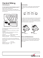
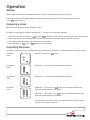
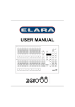
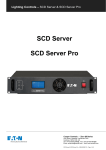
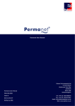
Chilli Control Panel
Installation guide
Introduction
Welcome
Supplied parts
The 2, 5, 7, and 10 button Chilli Control Panels from
Cooper Controls provide an elegant solution. These
buttons are used to output a memory or sequence which
has been previously programmed into the Chilli / Spice
dimmers on the network or to turn the outputs off.
Where fitted, raise, and lower buttons compliment the
usual selection buttons to allow immediate changes to
the intensity of any memory.
An optional infrared remote control allows similar
functionality from anywhere within the room via the
detector built into the front panel of the Chilli Control
Panel (2, 5, and 7 button only). The Chilli Control Panel
is connected to the dimmers using a Chilli Network
connection.
Main body
Front cover
Screws
Dimensions
86.01 mm (3.39 in)
39.01 mm
(1.54 in)
Fixing to a wallbox
86.01 mm (3.39 in)
The Chilli Control Panel fits into standard single gang
47mm deep UK backbox. Backboxes available from
Cooper Controls.
Series 3 Panels (Clip-on Cover)
Use the screws provided to attach the panel to the
backbox before clipping the front cover onto the
assembly.
Control Wiring
Chilli Network
Termination
The Chilli Control Panel uses Chilli Network connections
to ensure reliable and responsive transfer of control
signals between multiple devices.
Cable connections are made to a removable 5-way
connector block located at the rear of the Classic Control
Panel main body:
The Chilli Network is a ‘daisy chain’ protocol that requires
termination on the device located at either end of the
chain.
Device
CAN-L
(blue)
SHIELD
(brown
pair)
CAN-H
(blue/
white)
CAN
TERM
Device
The Chilli Control Panel is supplied with termination enabled
as standard. If the Chilli Control Panel is not connected as
an end device in the chain, you need to disable termination.
To disable termination, move the jumper from the upper two
pins to the lower pins, as shown here:
KEY3
The following cable strategies may be used for wiring
the Chilli Network.
It is not recommended to mix cable types in a single
installation.
Use Belden cable to maximise network runs up to
1000m without a bridge/repeater.
Cable type: Belden 1502R or 1502P
Maximum cable length: 1000m (3275 ft.)
Devices per segment: 100 (without bridge or repeater)
Use CAT5 FTP for economy and wide availability, but
there are tighter limitations on the network run without a
bridge/repeater.
Cable type: Maximum cable length:
Devices per segment:
Device
+12V
(orange
pair)
KEY1
KEY2
OV
SHIELD
OV
(green
Pair)
Device
CAT 5 FTP
305m (1000 ft.)
100
Termination on
Termination off
Care and Maintenance
The front cover plate should only be cleaned gently with
a clean, damp cloth. Abrasive cleaners, polishes, solvent
based cleaning agents, or alkali based cleaners should
not be used.
Operation
Startup
When a Chilli Control Panel is powered up the LEDs in all the buttons will flash once and then go off.
The panel then goes into its default state with all the button LEDs off, except for the 10 button panel in which the
“1-6” 1-6 button only is lit.
Assigning an Area
All Chilli Control Panels are initially assigned to Area 1.
To assign a control panel to a specific area number (1 - 10) carry out the following operation:
1.
2.
3.
4.
Press and hold down the Memory 1 1 and OFF OFF buttons for a few seconds until all the LEDs in the buttons flash.
Send a play memory/area message on the network, from another control panel, master controller or dimmer.
The control panel is assigned to the area number in the message.
Press the Memory 1 1 or OFF OFF button to exit setup mode.
Outputting Memories
To playback (output) one of the memories previously programmed in the Chilli Pro or Spice dimmers on the Chilli network.
Two Button
Panel
Memory 1: Press the ‘1’
1
button.
OFF
chilli net
Memories 1 - 4: Press the corresponding memory button.
Five Button
Panel
OFF
chilli net
Memories 1 - 4: Press the corresponding memory button.
Seven Button
Panel
OFF
chilli net
Memories 1 - 6: Press the 1-6 1-6 button (if not already selected), then
press the corresponding memory button.
Ten Button
Panel
5
6
SEQU
1-6
OFF
7-12
chilli net
Memories 7 - 12: Press the 7-12 7-12 button (if not already selected), then
press the corresponding memory button.
The LED light in the memory button is lit and the outputs fade to the memory levels in the memory’s fade time.
Raise and Lower Buttons
The 7 button Chilli Control Panel has Raise and Lower buttons which are used to adjust memory output levels.
The Raise
and Lower
buttons only affect the relevant dimmer channels on the network if memory 1, 2, 3, or
4 for the corresponding area is currently being output.
If memories 5 - 12 or a sequence are being output for the corresponding area, the Raise and Lower buttons will have
no effect.
The Raise button increases the output levels of all channels in the memory for the corresponding area by 5%.
Note - channels programmed at zero, remain at zero.
The Lower button decreases the output levels of all channels in the memory for the corresponding area by 5%.
Removing A Memory
To remove a memory from the outputs, press the OFF OFF button on the control panel. The LED in the button is lit.
The memory being output in the corresponding area will be faded out over three seconds.
Sequences
The 10 button Chilli Control Panel can be used to playback (output) any of the three sequences programmed in the
Chilli dimmers on the network for the corresponding area. Sequences can be stopped from any Chilli Control Panel on
the network that is assigned to the same area in which the sequence is running.
Starting a Sequence
Press the SEQUENCE SEQ button once, twice or three times to start sequence 1, 2 or 3 respectively. The light in the
SEQUENCE button will turn on to indicate that a sequence is running and the light in button 1-3 will turn on to indicate
which sequence (1-3) is running. When a sequence is running, each press of the SEQUENCE button will stop the current sequence and start the next sequence running automatically.
Stopping a Sequence
To stop a sequence that is running in an area, output a memory in that area, or press the OFF button on a control panel
assigned to that area. The light in the SEQUENCE button will turn off.
Network Locking
All control panels can be remotely locked and unlocked from a Master Controller via the network.
Manual Locking
The 10 button Chilli Control Panel can be locked and unlocked manually. To Lock: press and hold the “1-6” and “7-12”
buttons together for approximately 5 seconds, until all 10 lights in the buttons will turn on to indicate that the lock state
has changed.
Manual Unlocking
Press and hold the “1-6” and “7-12” buttons together for approximately 5 seconds, until lights in buttons 1, 3 and 5
are lit to indicate that the lock state has changed.
Key 1 Lock
Last Man Out Control Panel
Last Man Out panels are fitted with a keyswitch. When the keyswitch is operated, the
control panel sends out an ‘OFF’ message for all areas after a delay of 30 seconds.
Key 2
When Key 2 is connected to 0 volts, all button presses on control panel are ignored
and a last man out message is sent out.
KEY1
KEY2
OV
SHIELD
When Key 1 is connected to 0 volts, all button presses on control panel are ignored.
KEY3
CAN
TERM
Key 3
When Key 3 connected to 0 volts, button presses on control panel are not ignored
and a last man out message is sent out.
Chilli Network Alarm State
Chilli dimmers on the network have an Alarm Input. When this alarm input is activated, or changes from active to
inactive, the dimmer sends out Alarm On and Alarm Off messages respectively. The dimmers ignore all messages
from the control panels when the alarm state is active.
Infra Red Handset
The Infra Red (IR) handset has the following functions:
1.
2.
3.
4.
Buttons 1-4 turn on memories 1-4.
Off button turns memories off.
Raise button – increases the output Levels of the memory that is playing.
Lower button – increases the Levels of the memory that is playing.
Note 1: channels programmed at zero, remain at zero when the Raise button is pressed.
Note 2: The IR handset is not area specific. Consequently, when a memory is initiated from the handset, that memory is played
in all areas.
Zero 88
Usk House, Llantarnam Park,
Cwmbran, NP44 3HD. UK
Tel: +44 (0)1633 838088
Fax: +44 (0)1633 867880
www.zero88.com
All products manufactured by Cooper Controls and identified with the Zero 88 brand are warranted to be free from defects
in material and workmanship and shall conform to and perform in accordance with Seller’s written specifications.
For detailed warranty information, visit our website at www.zero88.com
This warranty will be limited to the repair or replacement, at Seller’s discretion, of any such goods found to be defective,
upon their authorized return to Seller. This limited warranty does not apply if the goods have been damaged by accident,
abuse, misuse, modification or misapplication, by damage during shipment or by improper service.
There are no warranties, which extend beyond the hereinabove-limited warranty, INCLUDING, BUT NOT LIMITED TO,
THE IMPLIED WARRANTY OF MERCHANTABILITY AND THE IMPLIED WARRANTY OF FITNESS.
No employee, agent, dealer, or other person is authorized to give any warranties on behalf of the Seller or to assume
for the Seller any other liability in connection with any of its goods except in writing and signed by the Seller. The Seller
makes no representation that the goods comply with any present or future federal, state or local regulation or ordinance.
Compliance is the Buyer’s responsibility.
The use of the Seller’s goods should be in accordance with the provision of UL and/or other industry or military standards
that are pertinent to the particular end use. Installation or use not in accordance with these codes and standards could be
hazardous.
North America Headquarters
International Headquarters
203 Cooper Circle
20 Greenhill Crescent
Peachtree City, GA 30269
Watford Business Park
P: 800-553-3879
F: 800-954-7016
www.coopercontrol.com
[email protected]
Watford, Herts, WD18 8XG. UK
P: +44 (0)1923 495495
F: +44 (0)1923 228796
www.coopercontrol.com
[email protected]
Document 73-843-00 IM8991 Iss.01