Transcript
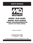
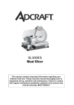
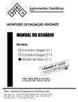
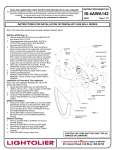
ISF:300
INSTRUCTION SHEET
07-01/Rev-03
INSTALLATION INSTRUCTIONS FOR 12V LOW VOLTAGE
AND 120V REMODELER
READ AND UNDERSTAND THESE INSTRUCTIONS BEFORE INSTALLING FIXTURE
This fixture is intended for installation in accordance with National Electrical Code or Canadian Electrical
Code (as applicable) and local regulations. To ensure full compliance with local codes and regulations, check with your local
electrical inspector before installation. To prevent electrical shock, turn off electricity at fuse box before proceeding.
Retain these instructions for maintenance reference.
DIA* = CEILING CUT-OUT
301MRE - 401MRE
300ES = 3-3/4" (95mm) Dia*
1" Max. ceiling thickness
NOTE: WARNING RISK OF FIRE
Transformer contains fixture thermal protector. Use only
replacement transformer obtained from LIGHTOLIER.
303MRE = 3-3/4" (95mm) Dia*
1/2" Max. ceiling thickness
SUPPLY
LEAD
COVER
BX
CONNECTOR
JUNCTION
BOX
FIG.1
FIG.2
INPUT (120V)
LAMP
NEUTRAL
GROUND
INPUT (120V)
NEUTRAL (white)
BLACK
NEUTRAL (white)
GROUND
WHITE
A. CEILING:
1. Cut an opening as indicated above. (Fig.1)
Note: Ensure that there is nothing to obstruct the
installation in the ceiling.
B. WIRE-IN:
1. Open junction box cover. (Fig.2)
2. Insert the supply lead into the junction box with a
BX connector (not included).
3. Ground the fixture.
4. Connect the white leads (NEUTRAL) together, and
the black leads (120V) together. (Fig.3, 4 or 5)
5. Close cover. (Fig.2)
Note: Be careful not to pinch leads.
C. HOUSING:
1. Slide the power pack and the housing together into
the ceiling. Snap into place. (Fig.6)
D. RESIDENCE MOUNTING FASTENERS
1. Screw both fasteners screws. (Fig.8)
OR
303MRE MOUNTING FASTENERS:
1. Place (3) holding springs, in the T slots. Slowly
push downward using a short handle screwdriver,
until trim is flush with ceiling, solidify with screws
(3) (included), (Fig.7)
ATTENTION: Insure that the spring is placed
correctly in the T slot, nice and straight then push
down slowly. The spring does not have to be
lowered completely in the slot.
CAUTION: The housing must not be used for
temporary lighting, a protective shield is
required for the lamp.
E. TRIM:
1. Install the trim using the appropriate instruction
sheet.
F. TRANSFORMER / REPLACEMENT:
(Models 301MRE, 303MRE, 401MRE)
Note: Before performing maintenance on the
transformer, make sure that the electrical supply to
the fixture is turned off.
1. Remove the junction box cover and disconnect all
wiring connected to the transformer. (Vig.9)
2. The transformer is held by double sided tape, rotate
with screwdriver under the transformer to loosen it.
(Fig.9)
3. Complete the connections (Fig.5) following the
wiring diagram.
303MRE
301MRE = 3-3/4" (95mm) Dia*
401MR = 4-3/4" (121mm) Dia*
1" Max. ceiling thickness
WHITE
300MR = 3-3/4" (95mm) Dia*
400MR = 4-3/4" (121mm) Dia*
1" Max. ceiling thickness
300ES
BLACK
300MR / 400MR
LAMP
THERMAL
PROTECTOR
BLUE
WHITE
JUNCTION
BOX
LOW VOLTAGE
TRANSFORMER
THERMAL
PROTECTOR
JUNCTION
BOX
FIG.3
(MR)
FIG.4
(ES)
GROUND
NEUTRAL (white)
INPUT (120V)
THERMAL
PROTECTOR
NEUTRAL (white)
BLACK
BLUE
LAMP
BLACK
JUNCTION BOX
LOW VOLTAGE
TRANSFORMER
FIG.5
(MRE)
SCREW
HOUSING
CEILING
POWER PACK
HOUSING
FIG.6
SCREWS
FASTENERS
"T"
SLOTS
RETAINING
SPRINGS
FIG.7
FIG.8
JUNCTION BOX
SCREWDRIVER
FIG.9