1
r
INSTRUCTION SHEET NO.
READ AND UNDERSTAND THESE INSTRUCTIONS BEFORE INSTALLING FIXTURE
Thisfixtureis intendedforinstallationinaccordancewiththe NationalElectrical Code and load regulations.
To assure full compliancewithlocalcodesandregulations,checkwithyourlocalelectricalinspectorbefore
installation. Toprevent electrical shock, turnoff electricity at fuse box before proceeding.
Retain these instructions for maintenance reference.
IS:6079
0493
Page 1 of 2
INSTALLATION FOR AITACHING EXTENSION WAND SLOPED CEILINGS ADAPTER
TO LYTESPAN TRACK. FOR USE WITH LYTESPAN” TRACK SYSTEMS ONLY
Extensionwandslopedceilingadaptercan be mountedon any Basic,Advent Multipointor MonopointTrackon tailings from 0° to 90° (vertical).
Notfor usewith Lytespota with attachmentfitting 7589.
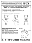
1. Grasp TOP FITTING at top of ADAPTER and insert it into the LYTESPAN TRACK. The LOCKING LEVER must be on the same side of the track as the BEAD.
(see Fig. 1.)
2. Rotate the TOP FI’ITING W’ clockwise, (See Fig. 2), until LOCKING LEVER snaps and locks in plats. (See Fig. 3.) Do not rotate adapter from LOWER FllllNG.
3. Loosen KNOB and set the lower haff of the ADAPTER to a vertical positionand tighten KNOB. (Fig, 4)
4. To Remove Depress LOCKING LEVER; then rotate TOP FllllNG 90° counter-dockwke. Do not rotate wand from LOWER FITTING,
LVTESPAN
TRACK
!lri
FITTING
BEAD
L
c
LOCKING
LEVER
‘“WERF’”’N
CLOCKWISE
-u
FIG. 2
FIG. 1
INSTRUCTIONS FOR CONVERTING
2 CIRCUIT TRACK SYSTEMS
NG
I
FIG. 3
I
FIG. 4
FITTING TO OPERATE ON
BRASS CONTACT
See Fig. 5, BRASS CONTACT can be raisedor lowered,Brokenline indicatespositionfor 1 circuit
/$
L::;;:G
track or lower circuitof 2 circuittrack system.
To mnverf attachment FllTING for upper circuitof 2 circJJittrack, raise BRASS CONTACT to high
position by Ming CONTACT as high as stop f.wrnits and CONTACT clicks into place.
FIG. 5
INSTRUCTIONS FOR AllACHING
EXTENSION WAND TO EXTENSION WAND SLOPED CEILING ADAPTER
1. Insert the WAND FllllNG into the LOWER FllllNG.
The LOCKING LEVER must be on the same side as the bead located at the bottom of the LOWER FllTING (See Fig. 6.) Rotate the WAND FllllNG
90° clockwise until LOCKING LEVER snaps and locks in place. (See Fig. 6,7, & 8).
2, To remove, depress LOCKING LEVER and rotate FllllNG 90° counterclockwise.
R/la
BEAD
LOCKING_
LEVER
BRASSCONTACT
“OWN
_
WAND
FllTNG
CLOCKWISE
1
FIG. 6
FIG. 7
i
FIG. 8
I
*
-
INSTRUCTION SHEET NO.
INSTALLATION FOR AITACHING EXTENSION WAND SLOPED
CEILINGS ADAPTER TO LYTESPAN TRACK. FOR USE WITH
LYTESPAN@ TRACK SYSTEMS ONLY (Continued)
1s:6079
0493
Page 2 of 2
INSTRUCTIONSFORAllACHING LYTESPOV FIXTURESWITHSQUATADAPTERTO WAND SLOPEDCEILINGADAPTER
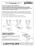
1. InserttheFIXTUREFllllNG intotheWANDSOCKET.
TheLOCKINGLEVERmustbeonthesamesideasthebeadlocatedatthebottomofthewand(SaaFig.9.)RotatetheFIXTUREFITTING90°clockwise
untilLOCKINGLEVERsnapsandlocksintoplace.(SeeFig.9, 10,& 11).
2. To remove, depress LOCKING LEVER and rotate FllllNG 90° counterdockvke,
=f&icL-
‘Go
kFIG.ll
LOW VOLTAGE LYTESPO~ TO WAND SLOPED CEILING ADAPTER
INSTRUCTIONS FOR AllACHING
1, Insert the FIXTURE FllllNG into the WAND SOCKET.
The LOCKING LEVER must be on the same side as the bead located at the bottom of the WAND SOCKET (See Fig. 8.) Rotate the FIXTURE
FllllNG 90° clockwise. (See Fig. 12, 13, & 14).
2, To remove, rotate FITTING 90° counterclockwise.
WAND
SOCKET
n
(--’
r--?
%
FIXTURE
FITTING
BEAO ~
LCCKINGLEVER
CLOCKWISE
@
\
/’
t~
INSTRUCTIONS
FOR A~ACHING
1
FIG. 12
LYTESPOT
\
FIG. 14
FIG. 13
WITH “T” ADAPTOR
\
TO WAND SLOPED CEILING ADAPTER
1. Align BEAD on WAND SOCKET with GROOVE in FITTING before inserting into WAND SOCKET, see Fig. 15. (If BEAD is NOT aligned
a potential hazard may result.)
2, Poshion LEVER as shown in Fig. 15.
3. Insert FllllNG into WAND SOCKET, Turn LEVER 90° to make mechanical and electrical connection, See Fig. 16.
4, To remove reverse procedure.
NOTE: If “T” ADAPTOR has a full gasket on top, remove 1/2” strip of cork between contact hub and grounding spring, If there is no
gasket, and a tighter fti to the WAND is desired, remove backing from enclosed GASKET. When centered on FllllNG apply pressure
on GASKET to secure it.
CONTACTHUB
WANO
SCCKET
-._—————
GROUNDINGSPRING
REMOVECORKAND
PAINT(IF PRESENT)
FROMTHISAREA
TO INSUREPROPER
GRouND,
BEAD _
~~GASKET ~
-
‘:-~
‘WK
GROOVE
\
FllllNG
1
$
“
RELEASE
LEVER
‘4
FIG. 15
FIG. 16
FIG. 17