1
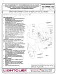
READ AND UNDERSTAND THESE INSTRUCTIONS BEFORE INSTALLING LUMINAIRE INSTRUCTION SHEET NO. This luminaire is intended for installation in accordance with the National Electrical Code and local regulations. To assure full compliance with local codes and regulations, check with your local electrical inspector before installation. To prevent electric shock, turn off electricity at fuse box before proceeding. IS:4A28442 Retain these instructions for maintenance reference. Page 1 of 2 A0501 INSTRUCTIONS FOR INSTALLATION OF PENDALUX PENDANT SERIES Note: This instruction sheet covers several luminaire (fixture) styles. Although suspension, chassis, lamp type and diffuser may vary from that shown, installation is the same. SWIVEL BALL INSTALLATION (Fig. 1): 1. 2. After opening carton and removing top packaging material, allow CHASSIS to remain in carton for protection. Assemble SUSPENSION system following the appropriate instructions outlined below. SUSPENSION Suspension Assembly: Single Stem Suspensions (4SB1 Series): 1. 2. If no extension kit is to be used; cut three wires (BLACK, WHITE and GREEN) no less than 6” above SWIVEL BALL. Strip back insulation from each wire approximately 3/8” from each end (Fig. 1). If an extension kit is to be used, follow instructions provided with extension kit. Multi-Stem, Contemporary and Traditional 3-Arm Suspensions (4SB2, 4SB3 & 4SB4 Series): 1. 2. 3. 4. 5. MALE CONNECTOR SUSPENSION PLATE RED WIRE FEMALE CONNECTOR SCREW If no extension kit is to be used; cut three wires (BLACK, WHITE and GREEN) no less than 6” above SWIVEL BALL. Strip back insulation from each wire approximately 3/8” from each end (Fig. 1). If extension kit is not to be used, thread UPPER STEM into THREAD ADAPTOR until tight (Fig. 1). Using ALLEN WRENCH provided tighten two SET SCREWS in the sides of THREADED ADAPTOR securing UPPER STEM in position. Cut three wires (BLACK, WHITE and GREEN) no less than 6” above SWIVEL BALL. Strip back insulation from each wire approximately 3/8” from each end (Fig. 1). If an extension kit is to be used, follow instructions provided with extension kit. NOTE: For the Traditional 3-Arm suspensions, the upper half of COLLECTOR BALL can be pulled upward to gain access to THREADED ADAPTOR (Fig. 8). CHASSIS FIG. 1 RED WIRE FIG. 2 Suspension Installation: 1. 2. 3. 4. 5. 6. 7. Position SUSPENSION next to CHASSIS and insert MALE CONNECTOR from SUSPENSION into FEMALE CONNECTOR and snap together. Pass RED WIRE from CHASSIS up through CENTER PIPE on SUSPENSION. If necessary, cut and strip back insulation on RED WIRE as done in step one under suspension assembly above. Loosen three SCREWS on the top of CHASSIS as shown in fig. 1. Position KEYSLOTS in SUSPENSION PLATE over three SCREWS on top of CHASSIS (Fig. 1). Twist SUSPENSION PLATE clockwise allowing three SCREW HEADS to pass over BUMPS on the sides of KEYSLOTS. Secure SUSPENSION in place by fully tightening three SCREWS. BLACK WIRES GREEN WIRES WHITE WIRES BUMP FIG. 3 SCREWHEAD KEYSLOT CAUTION: USE LAMP WATTAGE AND TYPE AS MARKED ON LUMINAIRE A COMPANY 631 Airport Road, Fall River, MA 02720 INSTRUCTION SHEET NO. READ AND UNDERSTAND THESE INSTRUCTIONS BEFORE INSTALLING FIXTURE IS:4A28442 This luminaire is intended for installation in accordance with the National Electrical Code and local regulations. To assure full compliance with local codes and regulations, check with your local electrical inspector before installation. To prevent electric shock, turn off electricity at fuse box before proceeding. A0501 Page 2 of 2 Retain these instructions for maintenance reference. Final Installation: 1. 2. 3. WIRE NUT If a SUPPORT PLATE is provided (Fig. 4), drop CROSSBAR down into SUPPORT PLATE as shown. Using appropriate slots in CROSSBAR, secure CROSSBAR and SUPPORT PLATE to OUTLET BOX using OUTLET BOX SCREWS (provided with outlet box). If SUPPORT PLATE is being used, secure SUPPORT PLATE directly to ceiling surface using four MOUNTING HOLES. Use appropriate fasteners for the type of ceiling (i.e. wood screws, molly bolts, etc.). SUPPORT PLATE AUXILIARY FASTENING HARDWARE CANOPY CAUTION: Luminaire may weigh up to 40 lbs. Always use Support Plate (when provided) with the appropriate mounting hardware. 4. 5. 6. OUTER DIFFUSER Slide CANOPY over the SWIVEL BALL (Fig. 6). Raise CHASSIS and SUSPENSION assembly to CROSS BAR. Position SWIVEL BALL through the opening in the end of the CROSSBAR as shown in Fig.5. Allow SWIVEL BALL to rest down inside the CROSS BAR making certain the TAB on CROSSBAR is aligned with slot in SWIVEL BALL. SUPPORT CAP FIG. 4 DECORATIVE KNOB Wiring Luminaire: Conventional Wiring (all lamps on, single switch): 1. OUTLET BOX SCREWS OUTLET BOX CROSSBAR CROSSBAR CLIP Make connections: BLACK and RED luminaire leads to hot supply lead; white luminaire lead to neutral (white) supply lead. Green luminaire lead is a ground wire and must be connected to grounding terminal or ground lead inside OUTLET BOX. Use WIRE NUTS (local hardware item). Push supply wires and connections back into OUTLET BOX. CROSS BAR SCREW SWIVEL BALL CLIP SCREW Multi-Level Wiring (all lamps on or only two lamps on, two switches): FIG. 5 SCREW Note: Requires two separately switched hot supply leads. Option not available on two lamp units. 1. 2. Make connections: BLACK luminaire lead to first hot supply lead; RED luminaire lead to second hot supply lead; white luminaire lead to neutral (white) supply lead. Green luminaire lead is a ground wire and must be connected to grounding terminal or ground lead inside OUTLET BOX. Use WIRE NUTS (local hardware item). Push supply wires and connections back into OUTLET BOX. Snap CROSSBAR CLIP onto CROSSBAR as shown in Fig. 5 and secure CLIP in place by tightening CLIP SCREW. Canopy Installation: 1. 2. 3. INNER CANOPY CANOPY FIG. 6 SWIVEL BRACKET SWIVEL BRACKET COLLECTOR FIG. 7 Slide CANOPY up STEM aligning SLOTS in INNER CANOPY with SCREWS protruding from CROSSBAR (Fig. 6). Rotate CANOPY clockwise until CANOPY snaps securely against ceiling. Install recommended lamps Final Suspension Assembly: Traditional 3-Arm Suspensions 1. Pass un-threaded end of ROD up into hole in side of COLLECTOR (Fig. 8). Secure in position by threading ROD into SWIVEL BRACKET (Fig. 7). Repeat for remaining RODS. PLUNGER CABLE FIG. 9 ROD Contemporary 3-Cable Suspensions 1. 2. Thread PLUNGER into SWIVEL BRACKET Push end of CABLE through PLUNGER opening until CABLE is tight (Fig. 9). Repeat for remaining CABLES. FIG. 8 A COMPANY 631 Airport Road, Fall River, MA 02720