1
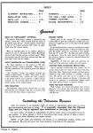
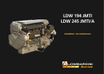
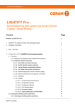
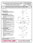
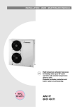
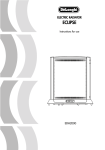
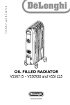
INSTALLATION - OPERATING - SERVICE MANUAL
Inertial storage tanks with
pumping assembly.
HPA
65-145
INDEX
U
I
A
General warnings
2
I
Weights and dimensions
9
U
I
A
Fundamental safety rules
2
I
Handling
10
I
A
Description of standard unit
3
I
A
Positioning
10
I
A
Use with chillers
3
I
A
Hydraulic connections
11
I
A
Identification
4
I
A
Electrical connections
13
I
A
Technical data
4
I
Filling and emptying
14
Internal hydraulic circuit
6
I
A
Preparing for first start-up
15
I
I
A
Pump
6
I
A
Routine maintenance
15
U
I
A
Start-up
7
I
A
Troubleshooting
16
U
I
A
Shutting down for long periods
7
U
I
A
Cleaning
7
U
I
A
Maintenance
7
U
I
A
Useful information
8
Receiving the product
9
I
The following symbols are used in this publication and inside the unit:
U
I
A
User
Important
Installer
Prohibition
Assistance
Danger voltage
Climaveneta is part of the Eurovent certification programme.
The manufacturer reserves the right to modify the data in this manual without warning.
HPA
English 05/2000
1
GENERAL WARNINGS
After removing the packaging, make sure the unit is
complete and undamaged. If this is not so, contact
the De’Longhi dealer who sold the appliance.
De’Longhi appliances must be installed by companies authorised according to Law no. 46 of March 5,
1990. On completion of installation, they must issue
the owner with a certificate stating that installation
has been carried out in respect of good work practices, in accordance with current legislation and following the instructions provided by De’Longhi in
this manual.
These appliances have been designed and produced
for use in combination with chillers for air conditioning and/or heating.They must be used in installations
compatible with their performance characteristics.
Incorrect installation, regulation or maintenance or
improper use absolves De’Longhi from all contractual and non-contractual liability for damage to persons, animals or things.
U
I
A
If the unit is not used for long periods, proceed as
follows:
- Place the mains switch in the “off” position
- Close the water cocks
- If there is a risk of freezing, make sure the installation contains antifreeze or empty the water circuit.
This instruction manual is an integral part of the
appliance and must therefore be kept carefully. If the
appliance is sold or transferred to alternative premises, the manual should ALWAYS be passed to the
new owner/user. If it is lost or damaged, ask your
local De’Longhi Technical Assistance Service for a
replacement.
All repairs and maintenance must be carried out by
the De’Longhi Technical Assistance Service or
authorised personnel only following the instructions
in this manual The appliance must under no circumstances be modified or tampered with as this may
create situations of risk. Failure to observe this condition absolves the manufacturer of all liability for
resulting damage.
In the event of water leaks, turn the mains switch to
“off” and close the water cocks.
Contact the De’Longhi Technical Assistance Service or professionally qualified personnel promptly.
Do not intervene on the appliance personally.
FUNDAMENTAL SAFETY RULES
When operating equipment involving the use of electricity
and water, a number of fundamental safety rules must be
observed, namely:
The unit must not be used by children or by unfit
persons without suitable supervision.
Do not touch the unit with bare feet or with wet
or damp parts of the body.
Before cleaning, disconnect the appliance from the
mains electricity supply by placing the mains switch
in the “off” position.
2
English 05/2000
U
I
A
Do not modify safety or regulation devices without
authorisation and instructions from the manufacturer.
Do not pull, detach or twist the electrical cables
coming from the unit, even when disconnected
from the mains electricity supply.
Do not open doors or hatches providing access to
the inside of the appliance without first placing the
mains switch in the “off” position.
Do not dispose of or abandon packaging material
(cardboard, staples, plastic bags, etc) in the environment and keep it out of reach of children as it may
constitute a hazard.
HPA
I
A
DESCRIPTION OF APPLIANCE
These storage tanks are designed for use in combination
with chillers in small and medium capacity installations.
They are designed for internal use. They are supplied complete with insulated tank, pump, expansion tank, drain cock,
safety valve, air vent valve and pressure gauge.
HPA storage tanks are functionally dependent on the connected HRH/N or HRA/N chiller.
HPA 65 B1 - 145 H1 MODEL
5
1
2
3
6
7
8
4
9
10
1
2
3
4
5
Inspection panel
Expansion tank
Pump
Tank
Manual air vent valve
I
6
7
8
9
10
Safety valve
Pressure gauge
Fill/top-up cock
Water connections
Drain cock
A
USE WITH CHILLERS
HPA storage tanks are designed for use with HRH/N or HRA/N chillers.
HPA STORAGE TANKS
65 B1
145 H1
0011
0021
0025
0031
•
•
•
•
•
•
•
•
HRH-HRHN CHILLERS
0041
0051
0061
•
•
HPA STORAGE TANKS
65 B1
HPA
0011
0021
0025
•
•
•
•
•
0071
0091
0101
0121
•
•
•
•
•
•
HRA-HRN CHILLERS
0031
0041
•
•
0051
0061
•
•
English 05/2000
3
IIDENTIFICATION
I
A
I
A
The HPA storage tank can be identified by the:
- Packing label
De' Longhi S.p.a. - 31100 Treviso / Italia
Via L.Seitz, 47 - tel. 04224131 fax 0422413659
MODEL:
VOLTAGE:
CODE:
- Technical rating plate
Giving the technical data and performance characteristics
of the storage tank. If this is lost, ask the De’Longhi Technical Assistance Service for a replacement.
MODEL
REGISTRATION NO.
CODE
STORAGE TANK CAPACITY
EXPANSION TANK CAPACITY
MAX.WORKING PRESSURE
EXPANSION TANK PRE-PRESSURISING
PUMP
ELECTRICAL POWER SUPPLY
MAX. POWER INPUT
MAX. POWER INPUT
SAFETY VALVE CALIBRATION
OPERATING WEIGHT
YEAR OF FABRICATION
l
l
bars
bars
N°
V - ~ - Hz
kW
A
bars
kg
Tampering with or the removal or absence of rating plates
problems during installation and maintenance.
or other means enabling the unit to be identified causes
TECHNICAL DATA
Description
Storage tank capacity
Expansion tank capacity
Expansion tank pre-pressurising
Maximum working pressure
Electrical power supply
Maximum absorbed power
Maximum absorbed current
Start-up current
Safety valve calibration
Operating weight
4
English 05/2000
Models
65 B1
44
2
1,5
5
145 H1
142
5
1,5
5
I
l
bars
bars
V/ph/Hz
kW
A
A
bars
kg
230 ~ 50
0,21
0,92
3,7
3
79
0,55
3,80
15,2
3
220
HPA
QUANTITY OF WATER IN INSTALLATION
Model HRH-N
Minimum
Recommended
0011
0021
0025
0031
0041
0051
0061
0071
0091
0101
0121
50
70
80
100
110
130
150
220
250
300
350
100-140 130-180 150-210 170-240 230-300 270-360 320-430 410-550 490660 580-770 700-930
Model HRA-N
Minimum
Recommended
0011
50
100-140
0021
70
130-180
0025
80
150-210
0031
100
170-240
0041
110
230-300
0051
130
270-360
0061
150
320-430
Litres
Litres
Litres
Litres
USEFUL STORAGE TANK HEAD CURVES (*)
mCA
KPa
21,3
20,3
19,3
18,3
17,3
16,3
15,2
14,2
13,2
12,2
11,2
10,1
9,1
8,1
7,1
6,1
5,0
4,0
3,0
2,0
1,0
0
210
200
190
180
170
160
150
140
130
120
110
100
90
80
70
60
50
40
30
20
10
0
(1) Useful head 65 lt. storage tank kit
(for units 0011÷0061)
HPA.65.B.I.
2
(2) Useful head 145 lt. storage tank kit
(for units 0071÷0121)
HPA.145.H.I.
1
0,0
0,5
1,0
1,5
2,0
2,5
3,0
3,5
4,0
4,5
5,0
5,5
6,0
6,5
7,0
7,5
8,0
0,13 0,27 0,41 0,55 0,69 0,83 0,97 1,11 1,25 1,38 1,52 1,66 1,80 1,94 2,08 2,22
m3/h
L/s
(*) To obtain the useful heads delivered to the installation, subtract the pressure drop of the plate heat exchanger.
HEAT EXCHANGER PRESSURE DROP (INSTALLATION WATER SIDE)
Model
HRA-HRN/HRH-HRHN
Water
flow
m3/h
l/sec
0011
0021
0025
0031
Pressure
drop
kPa
kPa
kPa
kPa
Model
HRA-HRN/HRH-HRHN
Water
flow
m3/h
l/sec
0041
0051
0061
Pressure
drop
kPa
kPa
kPa
Model
HRA-HRN/HRH-HRHN
Water
flow
m3/h
l/sec
0071
0091
00101
00121
Pressure
drop
kPa
kPa
kPa
kPa
0,40
0,6
0,8
0,90 1,00
1,2
1,4
1,6
1,7
2,0
2,2
0,111 0,167 0,222 0,250 0,278 0,333 0,389 0,444 0,500 0,555 0,611
5
-
11
8
7
-
20
15
10
9
26
18
16
11
31
23
19
17
44
33
24
20
45
35
25
54
46
36
40
55
-
0,8
1,2
1,6
2,1
2,6
2,8
2,9
3,1
3,6
4,0
4,4
0,222 0,333 0,444 0,555 0,667 0,778 0,805 0,889 1,000 1,111 1,222
-
8
5
-
12
10
-
21
14
12
32
24
16
37
28
24
40
30
25
46
34
27
46
36
45
2,4
3,1
3,8
4,6
5,3
5,9
6,5
6,6
7,3
8,0
0,667 0,861 1,055 1,250 1,444 1,639 1,805 1,833 2,028 2,222
12
19
-
20
15
11
8
30
22
17
12
44
33
26
18
58
44
34
24
72
54
42
30
66
52
36
68
53
38
64
46
4,7
1,3
54
-
8,7
2,41
9,4
2,61
66
77
77
56
Note: The highlighted values refer to the nominal flow rate
HPA
English 05/2000
5
I
INTERNAL HYDRAULIC CIRCUIT
HRH-HRHN or HRA-HRN CHILLER
6
9
7
DELIVERY TO INSTALLATION
6
4
1
10
3
11
2
RETURN FROM INSTALLATION
5
8
HPA STORAGE TANK
1
2
3
4
5
6
Pressure gauge
Pump
Safety valve
Expansion tank
Fill/top-up cock
Temperature sensor
7
8
9
10
11
INSTALLATION FILL
DRAIN
Differential pressure switch
Drain cock
Plate heat exchanger
Tank
Manual air vent valve
I
PUMP
The HPA storage tank is supplied connected to a pump.
When started up for the first time and at least
once a year, you are recommended to control
the shaft rotation as, particularly after long
periods not in use, deposits and/or residues may
prevent free rotation.
The pump must never be operated without
water.
6
English 05/2000
HPA
A
U
I
A
After first start-up by the Technical Assistance Service, the
HPA storage tank is regulated in “automatic” and requires
no further action.
U
I
A
To deactivate the unit, follow the instructions in the
HRH/N or HRA/N chiller instruction manual.
U
I
A
Cleaning by the user is limited to the external panelling.
Use a cloth moistened with soapy water only.
In the case of stubborn marks, moisten the cloth with a
mixture of 50% water and denatured alcohol with specific
products.
After cleaning, dry the surface thoroughly.
U
I
A
STARTING UP
The HPA storage tank is functionally dependent on the
connected HRH/N or HRA/N chiller.
SHUTTING DOWN FOR LONG PERIODS
To begin operating the unit again after a long period
of inactivity, contact the De’Longhi Technical Assistance Service.
CLEANING
Never use a sponge with abrasive products or powder cleaning products.
Before cleaning, always disconnect the unit from the
mains electricity supply by placing the mains switch
in the “off” position.
MAINTENANCE
Regular maintenance is essential to maintain the long-term
efficient, safety and reliability of the HPA storage tank.
The maintenance plan for the HPA storage tank is the
same as for the HRH/N or HRA/N chiller connected.
HPA
English 05/2000
7
U
USEFUL INFORMATION
Dealer: ......................................................................................
Road ...........................................................................................
tel. ...............................................................................................
Installer: ...................................................................................
Mr ................................................................................................
Road ...........................................................................................
tel. ...............................................................................................
Technical Assistance: ..........................................................
Mr ................................................................................................
Road ...........................................................................................
tel. ...............................................................................................
DATE
8
English 05/2000
OPERATION
HPA
I
A
I
RECEIVING THE PRODUCT
HPA storage tanks are supplied in a single pack on a wooden pallet protected by cardboard packaging. They come
complete with:
– instruction manual
– guarantee certificate
– bar code labels
inserted in a plastic envelope inside the packaging.
I
The instruction manual is an integral part of the
unit and should therefore be read and kept carefully.
It is recommended that the packaging should not be
removed until the unit is located in the installation site.
Do not dispose of packaging elements in the environment or leave them within reach of children as they
are a potential hazard.
DIMENSIONS AND WEIGHTS
H
P
Modello
L (width)
P (depth)
H (height)
Gross weight
Net weight
HPA
L
65 BI
145 H1
400
450
950
40
35
800
600
950
85
78
English 05/2000
mm
mm
mm
kg
kg
9
I
HANDLING
After removing the packaging, the unit must be handled by
qualified personnel only using equipment suitable for the
weight of the HPA storage tank and in accordance with
accident prevention legislation.
During transport, the storage tank must be kept in
the vertical position.
I
POSITIONING
300
350
10
English 05/2000
HPA units are designed for internal use and must be installed in an area respecting the dimensions given in the figure
below. The distances specified are necessary to allow for
normal cleaning and maintenance operations to be carried
out.
500
The site for installation of the HPA units must be established by the installation designer or other competent professional and must take account of technical requisites,
regulations and legislation.
HPA units:
- Must be positioned on a level surface strong enough to
support the weight
- the foundation slab must be sufficiently rigid and must not
transmit vibrations to underlying or neighbouring rooms.
A
300
HPA
I
A
HYDRAULIC CONNECTIONS
HPA storage tanks are designed and constructed for use
with HRH/N or HRA/N chillers in heating and air conditioning installations.
The hydraulic connections are as follows:
Water inlet
A
Fill/top-up
B
Pressure release valve
C
Water outlet
Installation drain
D
Dimension
65B1
145H1
200
860
160
200
1”
320
760
85
140
1”1/4
A
B
C
D
Hydraulic connections inlet/outlet
FACTORY CONNECTIONS
mm
mm
mm
mm
Gas
CONNECTIONS TO BE CARRIED OUT BY THE INSTALLER
7
8
10
1
11
15
14
16
17
T
F
7
9
1
5
DELIVERY TO EQUIPMENT
3
12
4
1
15
14
2
6
9
9
1
2
3
4
5
6
7
Pressure gauge
Pump
Safety valve
Manual air vent valve
Expansion tank
Fill/top-up cock
Temperature sensor
HPA
8
9
10
11
12
13
14
Differential pressure switch
Drain/chemical wash valve
Heat exchanger unit side
Connection to storage tank
Tank
Filter
Vibration damper joint
13
RETURN FROM EQUIPMENT
15 Gate valve
16 Flow switch
17 Thermometer
English 05/2000
11
The choice and the installation of the components
in the system is the responsibility of the installer,
who must act according to the rules of good practice and the legislation in force.
The liquid flow switch must be dimensioned and
regulated in accordance with the hydraulic characteristics of the installation.
Install the flow switch half way along a straight horizontal stretch of piping at least a metre long.
Construct a unit by-pass to enable the piping to be
washed without the appliance being disconnected.
Use suitable diameter connection piping and avoid
exerting weight on the unit.
Installations containing antifreeze or covered by
specific legislation must be fitted with hydraulic
disconnectors.
REFERENCE VALUES
Reference values
PH
Electrical conductivity
Chlorine ions
Sulphuric acid ions
Total iron
Alkalinity M
Total hardness
Sulphur ions
Ammonia ions
Silicon ions
6-8
less than 200 mV/cm (25°C)
less than 50 ppm
less than 50 ppm
less than 0,3 ppm
less than 50 ppm
less than 35° f
nil
nil
less than 30 ppm
The manufacturer is not liable for obstruction,
breakage or noise resulting from the failure to install
filters, a flow switch or vibration dampers.
The storage tank safety valve outlet must be connected to an appropriate collection and disposal
system.
The manufacturer is not responsible for possible
flooding caused by operation of safety valves.
Fill/top-up water with particular characteristics
must be conditioned with suitable treatment
systems. See the table below for the reference
values.
To connect:
- Remove the protective plastic caps from the hydraulic
connections.
Connect the installation following the diagram on page 11.
To seal the threads, hemp and jointing paste is
recommended. Teflon should not be used in the presence of antifreeze.
Before connecting, make sure the pipes are free from
stones, and, rust, dross or other foreign bodies which
may damage the installation.
12
English 05/2000
HPA
I
A
ELECTRICAL CONNECTIONS
Electrical connections must be carried out by qualified personnel in respect of current legislation.
- Open the inspection panel
- Pass the electrical cable connected to the pump through
the cable grip on the storage tank
- Connect the HRH/N or HRA/N chiller following the
instructions given in the chiller manual
- After completing the electrical connections, replace the
inspection panel and screw up the fixing screws.
Electrical cables may enter the appliance ONLY in
the positions specifically described in this manual.
HPA
English 05/2000
13
I
FILLING AND EMPTYING THE INSTALLATION
FILLING
- Before filling, make sure the mains switch is on the “off”
position
- Make sure the drain cock is closed
- Open the inspection panel
- Open all air vents in the installation, terminals and storage tank
- Open the installation gate valves
- Begin filling, slowly opening the water filling/top-up cock
- When water begins to leak out of the air vent valves, close them and continuing filling until the specified pressure
is reached in the installation
- Close the fill/top-up cock
- Close the inspection panel.
The installation must be filled to a pressure of
between 1 and 2 bars.
This operation should be repeated after the unit
has been in operation for several hours. Control
installation pressure regularly and top-up if it drops
below 1 bar.
Check all joints for tightness.
EMPTYING
- Before emptying, make sure the mains switch is in the
“off’ position
- Open the inspection panel
- Make sure the fill/top-up water cock is closed
- Connect a plastic pipe to the drain cock hose connection
- Open all air vents in the installation, terminals, storage
tank and chiller
- Open the drain cock
- Close the inspection panel.
If the fluid in the circuit contains antifreeze, it
should not be allowed to drain freely as it is pollutant. It should be collected for possible reuse.
14
English 05/2000
HPA
I
A
PREPARING FOR FIRST START-UP
First start-up must be carried out by the De’Longhi Technical Assistance Service who will validate the Guarantee
Certificate on completion.
After installation and before starting up the HPA storage tank,
place the mains switch in the “off” position and make sure that
- All safety conditions have been respected
- The unit is adequately fixed to the surface it rests on
- All hydraulic and electrical connections have been carried
out as indicated in the instruction manual
I
- The hydraulic circuit is filled and vented
- The condensate drain is not obstructed
- All hydraulic circuit valves are open
- The pump rotates freely.
A
ROUTINE MAINTENANCE
The maintenance plan for the HPA storage tank is the
same as for the HRH/N or HRA/N chiller connected and
includes the following operations and checks:
- Filling of the water circuit
- Presence of air bubbles in the water circuit
HPA
-
Power supply voltage
Electrical absorption
tightness of electrical connections
Efficiency of pump.
English 05/2000
15
I
TROUBLESHOOTING
MALFUNCTION
The pump does not start-up
Pump noisy
Noise and vibrations
Safety valve activated
Leaks in hydraulic circuit
16
English 05/2000
CAUSE
A
REMEDY
Pump motor failure
Replace pump
No electricity
Check
Pump blocked
Unblock
Air in hydraulic circuit
Vent
Functioning out of the operating curve
Adjust calibrating valve
Contact between metal bodies
Check
Weak foundations
Repair
Loose screws
Tighten screws
Pressure in installation too high
Drain
Pressure low in expansion tank
Raise pressure
Leaks in hydraulic circuit
Check
HPA
COD. 5788001600
Dé Longhi spa 31100 TREVISO - Via L.Seitz, 47 Tel. 0422-413659