1
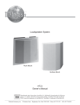
EC1-2
Lighting Systems
Page 1 of 3
Energos Control System 2-Light T8 per 4' (121.92cm) (Nominal) Louver
Feature Specifications – Energos Control System (For standard Energos fixtures consult appropriate EG spec sheets)
Feature Specifications
Electrical
Dedicated low voltage (24 VDC) circuit controls the Energos Control Systems. The
line voltage circuits control all the standard ballast functions including A/B switching, Dimming and Emergency Battery Pack operations.
Occupancy Sensors:
• Time delay is factory pre-set to 30 minutes.
• Time delay can be field adjusted from 30 minutes to a minimum of 30 seconds.
• Daylight hold-off is factory pre-set to 120 ft-candles (1291.67m-candles).
• Daylight hold-off is field adjustable from 120 ft-candles (1291.67m-candles)
down to 10 ft-candles (107.64m-candles).
• Sensors are designed for a detection area (sensitivity diameter) of 16'
(487.68cm) when suspended 10' (304.80cm) AFF. Lowering the sensor produces
a smaller area of detection. See chart and diagram for additional information.
Coverage Diameter
1. End Cap Sensor Mounting
2. Mid-mounted 8' (243.84cm)
Sensor Mounting
16' 0"
14' 5"
12' 10"
11' 3"
ECS occupancy sensors are available in two variations:
• Mounted in the end cap.
• The middle of an 8" (243.84cm) module.
Sensor Height AFF
The ECS system control-center is the Power Pack. The Power Pack, contained in
each Master Module, interrupts the circuits when parameters dictate. The Power
Pack can control up to 600 watts 120 VAC, and 1300 watts 277 VAC. A maximum
of 10 sensors can be used on a single Power Pack. There is no limitation to the
number of Power Packs that can be "daisy-chained" to a single ECS circuit.
7' 0"
8' 0"
9' 0"
10' 0"
Emergency battery packs can be used in conjunction with ECS for emergency
egress lighting since all listed packs operate for a minimum of 90 minutes.
EM Packs can be used as momentary lighting for emergency circuit for power
transitions, and smaller packs are recommended for this purpose.
Dimming ballasts can be used in conjunction with ECS. However, the control
system will only perform ON or OFF operations and will not affect the level of dimming set by the dimming ballasts.
Factory installed ballast disconnect allows the ballast to be disconnected from and
reconnected to incoming power under load without turning the entire circuit off.
Serial Row Linking (SRL) provides multiple continuous row communication.
For every run that SRL is required, order the appropriate SRL end set from page 2
of this Specification Sheet. Consult Energos Application Guide for more detailed
definitions and examples.
Mountings
Cable suspension distances are on 48" (121.92cm) and 96" (243.84cm) centers,
and consist of a 4 1/2" (11.43cm) diameter canopy finished white enamel. A 1/16"
(0.16cm) diameter stainless steel aircraft cable accomplishes suspension and is
adjustable from 12" (30.48cm) to 36" (91.44cm). Power feeds are 18 gauge silver
braided cord with clear jacket.
Energos Occupancy Sensor
Coverage Zone Chart
Height of Sensor
Broadcast Diameter
Task Diameter
10' 0" (304.80cm)
9' 0" (274.32cm)
8' 0" (243.84cm)
7' 0" (213.36cm)
16' 0" (487.68cm)
14' 5" (427.99cm)
12' 10" (391.16cm)
11' 3" (336.04cm)
8' 0" (243.84cm)
7' 3" (214.12cm)
6' 5" (184.15cm)
5' 7" (154.18cm)
Job Information
Type:
Job Name:
Cat. No.:
Lamp(s):
Notes:
631 Airport Road, Fall River, MA 02720 • (508) 679-8131 • Fax (508) 674-4710
We reserve the right to change details of design, materials and finish.
www.lightolier.com © 2008 Philips Group • C0808
Lighting Systems
Page 2 of 3
EC1-2
Energos Control System 2-Light T8 per 4' (121.92cm) (Nominal) Louver
Control Ordering Information
Family
Series
EC
1
Lamping &
Distribution
Ballast
Lamp
Shielding
2 = 2 lamp,
open top
5 = 2 lamp,
slotted top
reflector
See Chart on
Page 3
See Chart on
Page 3
P = Parabolic
Louver
Length
Finish
Voltage
Options
(Blank)
P
Ordering Instructions
End Cap ECS Systems
1. Order Master 4' (121.92cm) or 8' (243.84cm) ECS Module.
2. Order Power Feed End Set.
ECS Sensor Sample Runs
4 = 4' (121.92cm)
8 = 8' (243.84cm)
6 = 120 Vac Master
7 = 277 Vac Master
8 = 120 Vac Slave
9 = 277 Vac Slave
A = Aluminum
W= White
4 = 4 through wires
5 = 5 through wires
6 = 6 through wires
D = Dual Switch
T = Tandem Switch
E = Emergency
Continuous Row Mounted ECS Systems:
1. Determine run length
2. Order a minimum of one master per run. Please see Application Guide for
master requirements on runs that exceed 16' (487.68cm).
3. Order the required remaining Master and Slave modules to complete the run.
4. Order Power Feed End Set.
5. Order one CABLE ASSEMBLY per MODULE minus one per run.
6. Order additional Single Cable & Cord Sets for every Master Module in run.
ECS End Sets
4' Run: 4' (121.92cm) Master Module with Single Sensor End Set.
8' Run: 8' (243.84cm) Master Module and standard Energos End Set.
Single Sensor
End Set EC1SE36W
Dual Sensor
End Set EC1DE36W
Single Sensor SRL
End Set EC1SR36W
Dual Sensor SRL
End Set EC1DR36W
Standard End
Set EG1EC36W
SRL Standard
End Set EC1ER36W
Single Cable &
Power Cord EGCC36
8' Run: 8' (243.84cm) Master Module and Dual Sensor End Set.
12' Run:8' (243.84cm) Master Module, 4' (121.92cm) Slave Module, Dual
Sensor End Set, and Intermediate Cable Assembly.
16' Run:8' (243.84cm) Master Module, 8' (243.84cm) Slave Module, standard
Energos End Set, and Intermediate Cable Assembly.
16' Run:8' (243.84cm) Master Module, 8' (243.84cm) Slave Module, Single
Sensor End Set, and Intermediate Cable Assembly.
16' Run:8' (243.84cm) Master Module, 8' (243.84cm) Slave Module, Single
Sensor End Set, and Intermediate Cable Assembly.
Notes:
1. See page 1 of Specification Sheet or consult Application Guide for the definition of Serial
Row Linking (SRL).
2. Consult the matching EG specification sheet for Luminaire related specifications (i.e.
Housing materials, shielding, mounting dimensions, and photometry).
Job Information
Type:
631 Airport Road, Fall River, MA 02720 • (508) 679-8131 • Fax (508) 674-4710
We reserve the right to change details of design, materials and finish.
www.lightolier.com © 2008 Philips Group • C0808
Lighting Systems
Page 3 of 3
Energos Control System 2-Light T8 per 4' (121.92cm) (Nominal) Louver
Ballast Ordering Information
Design
Lamp Type
Ballast Factor
Start Type
THD %
Design
D
E
H
T8
T8
Dim T8
0.71
0.88
1.00/.05
Program
Program
Program
<10
<10
<10
A
B
C
D
E
F
G
H
I
J
K
L
Lamp and Ballast System Data
Design
DA
DB
DC
DD
DE
DF
DG
DH
DI
DJ
DK
DL
EA
EB
EC
ED
EE
EF
EG
EH
EI
EJ
EK
EL
HG
HH
HI
EC1-2
Lamp Type
Ballast
(T8 or T5) Factor (BF)
T8
T8
T8
T8
T8
T8
T8
T8
T8
T8
T8
T8
T8
T8
T8
T8
T8
T8
T8
T8
T8
T8
T8
T8
T8 DIM
T8 DIM
T8 DIM
0.71
0.71
0.71
0.71
0.71
0.71
0.71
0.71
0.71
0.71
0.71
0.71
0.88
0.88
0.88
0.88
0.88
0.88
0.88
0.88
0.88
0.88
0.88
0.88
1.0 / 0.5
1.0 / 0.5
1.0 / 0.5
Lamp Ordering Information
Rated Output
Lamp Type
Wattage
(Lumens)
T8
28
2725
T8
28
2725
T8
28
2725
T8
30
2850
T8
30
2850
T8
30
2850
T8
32
3000
T8
32
3000
T8
32
3000
T8
32
3100
T8
32
3100
T8
32
3150
Color (K)
3000
3500
4100
3000
3500
4100
3000
3500
4100
3000
3500
4100
Ballast
THD (%)
Lamp Rated
Wattage
Lamp
Rated
Output
Lamp
Color
(Kelvin)
IES Output
(lumens)
System
Input
Watts
System
Efficacy
(lum/watt)
System
Lamp Life
(Hours)
Start
Type
<10
<10
<10
<10
<10
<10
<10
<10
<10
<10
<10
<10
<10
<10
<10
<10
<10
<10
<10
<10
<10
<10
<10
<10
<10
<10
<10
28
28
28
30
30
30
32
32
32
32
32
32
28
28
28
30
30
30
32
32
32
32
32
32
32
32
32
2725
2725
2725
2850
2850
2850
3000
3000
3000
3100
3100
3150
2725
2725
2725
2850
2850
2850
3000
3000
3000
3100
3100
3150
2850
2850
2850
3000
3500
4100
3000
3500
4100
3000
3500
4100
3000
3500
4100
3000
3500
4100
3000
3500
4100
3000
3500
4100
3000
3500
4100
3000
3500
4100
2199
2199
2199
2299
2299
2299
2420
2420
2420
2501
2501
2541
2725
2725
2725
2850
2850
2850
3000
3000
3000
3100
3100
3150
2850 / 143
2850 / 143
2850 / 143
20.0
20.0
20.0
21.5
21.5
21.5
23.0
23.0
23.0
23.0
23.0
23.0
25.5
25.5
25.5
27.5
27.5
27.5
29.0
29.0
29.0
29.0
29.0
29.0
34 / 8
34 / 8
34 / 8
96.74
96.74
96.74
94.12
94.12
94.12
92.61
92.61
92.61
95.70
95.70
97.24
94.04
94.04
94.04
91.20
91.20
91.20
91.03
91.03
91.03
94.07
94.07
95.59
83.80
83.80
83.80
24000
24000
24000
24000
24000
24000
24000
24000
24000
30000
30000
30000
24000
24000
24000
24000
24000
24000
24000
24000
24000
24000
24000
24000
NA
NA
NA
Program
Program
Program
Program
Program
Program
Program
Program
Program
Program
Program
Program
Program
Program
Program
Program
Program
Program
Program
Program
Program
Program
Program
Program
Program
Program
Program
*25°C Rating
All data is per 1 lamp on a two lamp system at 277 VAC.
Data is based on Osram Sylvania specifications.
When ordering no lamps provided by Lightolier, use lamp code “Z”.
Do not alter lumen values or ballast factor light losses when completing
calculations using Energos IES files. Files have already been adjusted. The lumen
value for the lamp (within a Lighting Design program) will be the IES Ouput value
shown on this table.
The lamp life table demonstrates the effects of shortened cycle-times with both
program start and instant start ballasts. The graph shows that instant ballasts
are susceptible to shortened lamp life if short cycle periods of less than 3 hours
are used. For cycle periods of greater than 3 hours program start ballast are not
required.
Lamp Life Table using program start and instant start ballasts.
Job Information
Type:
631 Airport Road, Fall River, MA 02720 • (508) 679-8131 • Fax (508) 674-4710
We reserve the right to change details of design, materials and finish.
www.lightolier.com © 2008 Philips Group • C0808