1
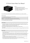
AN8 08P Series Intelligent Temperature controller
AN808P Programmable Intelligent Temperature Controller/
Adjustor User’s Manual
Features:
⊙ TC/ R TD/Analog signal universal input
⊙ Display ,alarm,adjust & communication function
⊙ Advacned Fuzzy algorithm & Two Degrees of Freedom PID
⊙ Optional output controls, modularization design,easy to change.
⊙ High anti-inteference.
⊙ 50 programm segments of controls
⊙ Color control bar display
Safe Caution
For your safe, please read the below content carefully before you use the meter !
Please comply with the below important points:
Warning An accident may happen if the operation does not comply with the instruction.
Notice
An operation that does not comply with the instruction may lead to product damage.
The instruction of the symbol in the manual is as below:
An accident danger may happen in a special condition.
Warning
1. A safety protection equipment must be installed or please contact with us for the relative information if the product is used under
the circumstance such as nuclear control, medical treatment equipment ,automobile, train, airplane, aviation, entertainment or safety
equipment, etc. Otherwise, it may cause serious loss, fire or person injury.
2. Apanel must be installed, otherwise it may cause creepage (leakage).
3. Do not touch wire connectors when the power is on, otherwise you may get an electric shock.
4. Do not dismantle or modify the product, If you have to do so, please contact with us first. Otherwise it may cause electric shock
and fire.
5. Please check the connection number while you connect the power supply wire or input signal, otherwise it may cause fire.
.
Caution
1. This product cannot be used outdoors. Otherwise the working life of the product will become shorter, or an electric shock accident
may happen.
2. When you connect wire to the power input connector or signal input connectors, the moment of the No.20AWG (0.50 mm2) scrwew
tweaked to the connector is 0.74n.m-0.9n.m. Otherwise the connectors may be damaged or get fire.
3. Please comply with the rated specifications. Otherwise it may cause fire after the working life of the product becomes shorter.
4. Do not use water or oil base cleaner to clean the product. Otherwise it may cause electric shock or fire, and damage the product.
5. This product should be avoid working under the circumstance that is flammable, explosive, moist, under sunshine, heat radiation and
vibration.
6. In this unit it must not have dust or deposit, otherwise it may cause fire or mechanical malfunction.
7. Do not use gasoline, chemical solvent to clean the cover of the product because such solvent can damage it. Please use some soft
cloth with water or alcohol to clean the plastic cover.
1.Code Illustration
AN808 P □ □ □ □
Input&communication: 0:One input without communication;8: One input wiht RS485 communication.
Alarm output:2:Two alarms 1: One alarms
(One more alarm will be added when not using Heating and cooling control )
Control output:R: Relay C:4~20mA current Q:SSR
Size(mm):4:48H×48W 6:96H×48W 7:72H×72W 8:48H×96W 9:96H×96W
16:160H×80W 80:80H×160W
AN808P series intelligent adjustor with 50 program segments of control function
2. Model Indication
Model
AN808P-4-R20
OUT1(Note①)
OUT2(Note②)
Alarm(Note③)
Communication
Relay
Relay
1
No
SSR
Relay
1
No
No
AN808P-4-Q20
AN808P-4-C20
4~20mA Current
Relay
1
AN808P-4-R18
SSR
Relay
No
RS485(MODBUS RTU)
AN808P-4-Q18
SSR
Relay
No
RS485(MODBUS RTU)
AN808P-4-C18
4~20mA Current
Relay
No
RS485(MODBUS RTU)
KKAN808PE01-A/0-1
Model
AN808P-□-R30
AN808P-□-Q30
AN808P-□-C30
AN808P-□-R38
AN808P-□-Q38
AN808P-□-C38
Alarm(Note③)
Communication
OUT1(Note①)
Relay
OUT2(Note②)
Relay
2
No
SSR
Relay
2
No
4~20mA Current
Relay
2
Relay
Relay
2
RS485(MODBUS RTU)
SSR
Relay
2
RS485(MODBUS RTU)
4~20mA Cureent
Relay
2
RS485(MODBUS RTU)
No
Note①: OUT1:
4~20mA Current output.load resisdence600Ωmax。Can switch to 4~20mA current output or control current output by
Relay output capacity:3A/250Vac SSR output capacity:30mA/ 24Vdc
Note②: OUT2:
Can be worked just under heating-cooling control(OT=3); under other control, worked as alarm 3 (size 48*48 works as alarm 2 when
without communication; size 48*48 work as alarm 1 when with communication. ). Relay output capacity:1A/250 Vac.
Note③: Alarm 3:
The load capability of Relay output is1A/250Vac
3.Main Technical Parameter
3.1 Whole controller parameters
Power supply
Total current
Ambient temperature
Humidity
Accuracy
Control mode
Communication
Panel protection level
Temperature excursion
Dielectric strength
100~240VAC/DC
<30mA(220VAC)
0~50℃
45~85%RH
±0.3%F.S±3digits 25℃
ON/OFF control,PID heating control,PID colding control,PID heating&colding control
RS485 communication interface MODBUS protocol
IP65
≤0.01%F.S/℃
Among power supply terminals,relay output terminals&signal terminals ≥2000VDC, between the
reciprocally isolated weak signal terminals ≥600VDC
3.2 Table ofInput parameters
No.
0
1
2
3
4
5
6
7
8
9
10
11
12
13
14
15
16
Symbol
Input type
K
J
E
T
B
R
S
N
Reserved
PT100
JPT100
CU50
CU100
Linear voltage
Linear current
Linear voltage
Linear resistance
Measuring range
-50~1300℃
-50~1200℃
-50~1000℃
-50~400℃
600~1800℃
-10~1700℃
-10~1600℃
-50~1200℃
-199.9~850.0℃
-199.9~500.0℃
-50.0~150.0℃
-50.0~150.0℃
0~50mV
4~20mA
0~10V
0~400Ω
Resolution
1℃
1℃
1℃
1℃
1℃
1℃
1℃
1℃
Input resistance
>100KΩ
>100KΩ
>100KΩ
>100KΩ
>100KΩ
>100KΩ
>100KΩ
>100KΩ
0.1℃
0.1℃
0.1℃
0.1℃
0.01%F.S
0.01%F.S
0.01%F.S
0.01%F.S
(0.2mA)
(0.2mA)
(0.2mA)
(0.2mA)
>100KΩ
110Ω
>100KΩ
(0.2mA)
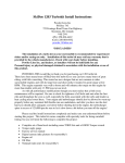
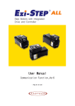
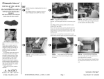
4. Panel Indication
PV display window: display measuring value
or parameter code
SV display window: display setting value
or parameter value
Control output volume indicating light bar
(AN808P-4 with no light bar)
Parameter selection/confirmation key
Function key
OUT1:OUT1 output indicating lamp
OUT2:OUT2 output indicating lamp
AL1:Alarm output1 indicating lamp
AL2:Alarm output2 indicating lamp
AL3:Alarm output3 indicating lamp
AT:Auto-tuning indicating lamp
Increase key
Decrease key
KKAN808PE01-A/0-2
5.Panel key operations
(1)SET key:in normal display status, press SET key to show setting menu, and press it for a few seconds to show the advanced setting menu.
(2) key:press key to make the parameter to flicker, then the parameer can be changed.
(3)▲ 、 key:to change parameters in setting status,and press SET key after changed.
(4)In advanced setting menu, press SET key for a few seconds to quit the menu and back to normal display status.
(5)In normal display status, press
for 3 seconds to start Auto-tuning function, then AT indicating lamp turns on.
(6)In normal display status, press ▲ key for a few seconds to enter the setting menu of program status; press for a few seconds
to enter into the setting menu of program parameter.
▲
6.Operation Process
Power on & Reset
Press SET for a few seconds
Measuring status
SET
Setting
menu
Press SET for a few seconds
output fuction
Press SET
setting menu
for a few seconds
SET
SET
SET
for a few seconds
SET
Input signal mode
SET
SET
Proportional
coefficient
Alarm2
SET
SET
Alarm1 mode
Alarm3
Derivative time
SET
ON/OFF control
hysteresis( effective
when OT=0)
SET
SET
PV bias value
SET
SET
Manual/auto
shift menu
SET
Passwork lock
coefficcient(effective
when OT=3)
SET
SET
Decimal point( Not effective for TC/ RTD input)
Heating,cooling control
dead area(effective
when OT=3)
SET
Filter constant
SET
SET
Alarm3 mode
Temperature units switch
SET
OUT2 control cycle
(effective when OT=3)
Meter
communication
address
SET
Upper limit signal
input mode
Alarm2 mode
Cooling proportion
SET
SET
SET
Alarm3 hysteresis
OUT1 control
cycle
SET
Lower limit signal
input mode
Alarm2 hysteresis
SET
Baud rate
SET
SET
Integral time
SET
SET
Communication
setting menu
Press SET
Control mode
Alarm1
SET
Iutput fuction
setting menu
Lower limit of
control output
SET
Upper limit of
control output
SET
Lower limit of transmit current output
SET
SET
Alarm1 hysteresis
SET
Upper limit of transmit current output
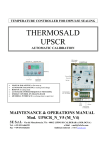
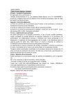
7. Program segment setting
The mode of program segment control setting:
⑴. Total 50 segments on program segment setting,each segment with 2 setting parameters:SV□□ 、ST □□.
⑵. Parameter SV □□ is the setting value of this segment. For example,SV 01 is set as 200 ,the controlling expected
value of this segment (the first segment)is 200 ℃。
Measuring status
▲
Programm segment
status setting menu
Press
to setting manu of
program segment parameters
Programm segment
parameter setting
menu
SET
SET
→
□□
STEP:select the setting
program segment
SET
Selections of program
operating status.
STOP、RUN or HOLD
is optional
□□
□□
SV□□: The□□segment
setting value
SET
SET
□□
□□
ST□□:Please refer to the
detailed indication as right:
controlling status ( please refer to below example1 ).
When ST □□ is set as-50 ~ -1 ,indicates skipping to the appointed segment.For example, when ST □□ =-45,
it indicates the current segment skipping to 45 segment;
When ST□□ setting value is 0,indicates the temperature reaching SV□□,
and skipping to next segment
( please refer to below example 1)
When ST□□ setting value is 1~ 1440,the unit is min, and it indicates when this segment is under operating ,it will
run in constant speed to the setting value within the setting time; the meter will decrease to 0 within countdown time
when it runs to ST □□.
If ST □□ has been decreased to 0,but the PV measuring value does not reach SV setting value, the program will
continue the operation of this segment till SV □□ value is accordance with PV value.For example: SV □□ =200,
ST □□ =10, the current temperature is 30℃,the programm will run at this segment by 10mins, and the temperature
increases 17 ℃ /min averagely.
(4).In normal display status,press
key for a few seconds to enter the program segment for parameter setting menu.
; status setting menu.You can select
(5).In normal display status,press ▲ key for a few seconds to enter program segment
RUN( Normal operation) ,STOP(Stop operation),HOLD(Keep the current SV value and not be changed anymore),total
3 status.
▲
Power on & reset
Press ▲ for a few seconds,
enter into program segment
status setting menu
⑶. Parameter ST □□ is the parameter of controlling status of this segment.
When ST □□ is set as -51,indicates to finish the program segment cotrol, and resumes to single setting value
Example 1:
To operate a treatment cycle curve,
Require the temperature reaching 300 ℃,
The temperatue is evenly rising from 300℃ to 500℃ (average10℃ per minute),
Then lower the temperature to 150 ℃,
After 60 mins kept in the status of 150℃,
Jump to operate the 10th program segment ,
Lower the temperature on the 10th program segment,
Stop on the 11th segment ,and
,
exit the program segment then
carry on the former programmed value (SV10=25) to
SV01=300 、ST01=0;
SV02=500 ST02=20;
SV03=150 、ST03=0;
SV04=150 、ST04=60;
ST05=-10;
SV10=25 、ST10=0;
ST11=-51;
control the temperature
KKAN808PE01-A/0- 3
8. Menu
Parameter
Indication
Setting range
Ex-factory setting
Setting Menu
Alarm 1 setting value
200
Alarm 2 setting value
600
Alarm 3 setting value
1000
Measuring value correction
0
Manual/Auto setting . 0: Manual; 1: semi-auto ( enter to AT by manual
1
0~2
setting ); 2: Auto (autoly enter into AT when power on)
When 0001, forbid to modify SV; When 0010, forbid to modify Menu
0
parameter; When 0011, forbid to modify SV and Menu.
Output Function Setting Menu
Control mode: 0: ON/OFF control; 1: Heating control; 2:Cooling control;
1
0~3
3: Heating&Cooling control
PID Menu: coeffcient of proportionality
10
PID Menu: integration time
240
PID Menu: derivative time
60
ON/OFF control hystersis (effective when in ON/OFF control mode)
2
OUT1 control period: current output is set as 0; SSR output is set as 1;
0~250
The range of Relay output is set ≥4
20
100
Cooling proportionality coefficient
1~250
20
-100~100
5
Alarm1 hystersis
0~1000
1
Alarm1 (refer to introduction of alarm function)
0~3
0
Alarm2 hystersis
0~1000
1
Alarm2 (refer to introduction of alarm function)
0~3
1
Alarm3 hystersis
0~1000
1
Alarm3 (refer to introduction of alarm function)
0~3
0
Control output low limit
0~99
0
1~100
100
OUT2 Controlling cycle ( the settable range is ≥4)
Heating & cooling control dead band
Control output high limit
Input Fucntion Setting Menu
Type of Input Signal
Refer to Input Parameter Table
K
The signal indicates the setting of low limit
Refer to Input Parameter Table
-50
The signal indicates the setting of high limit
Refer to Input Parameter Table
1300
Decimal point setting: the setting is effective when it’s not TC& RTD
0~3
0
1~250
60
signal input
Filter constant: when the parameter is big, the response is slow, and
vice versa .
0
0/1
0:℃ 1 :℉
Low limit value of analog ( to be effective when the ordered code
with communication )
High limit value of analog ( to be effective when ordered code
with communication)
FL~FH
-50
FL~FH
1300
Communication baud rate
4.8K, 9.6K
9.6K
Address of the Meter
0~250
1
Communication Setting Menu
Alarm Function Table
Alarm Code
Alarm Mode
Alarm output (AL1,AL2 are separated )
High limit absolute value alarm
Alarm:PV>AL
HY
0
AL
1
2
Temperature rising
Low limit absolute value alarm
High limit bias value alarm
SV
Low limit bias value alarm
3
Temperature droping
Cancel:PV≥AL+HY
AL
HY
SV+AL
HY
SV-AL
Cancel:PV≤AL-HY
Alarm:PV<AL
HY
Temperature droping
Formula
Temperature rising
Alarm:PV>AL+SV
Cancel:PV≤SV+AL-HY
Alarm:PV<SV-AL
SV
Cancel:PV≥SV-AL+HY
KKAN808PE01-A/0-4
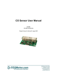
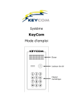
9.Panel dimension and mounting size (unit:mm)
Panel size
Side face size
A
Mounting size
G +0.5
-0
C
E
D
H
J +0.5
-0
B
K
F
Size code
A
B
C
D
E
F
G
H(Min)
J
K(Min)
4:(48*48)
48
48
101
10
91
45
45.5
25
45.5
25
94
91
45.5
25
91.5
25
6:(96*48)
48
96
100
6
7:(72*72)
72
72
100
10
90
67.5
68
25
68
25
8:(48*96)
96
100
6
94
45
91.5
25
45.5
25
25
48
9:(96*96)
96
96
101
10
91
90.5
91
25
91
80:(80*160)
160
80
102
10
92
76
154
30
76.5
30
92
153.5
30
154
30
16:(160*80)
Remark
80
160
102
10
76.5
Unit:(mm) Tolerance +0.5%(except indicating specially)
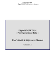
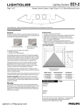
10.Connecting Drawing
Series
Model:AN808P-6/8
Accuracy:±0.3%F.S±3digits 25℃
Temperature drift:≤0.01%F.S/℃
Model:AN808P-7
Accuracny:±0.3%F.S±3digits 25℃
Temperature drift:≤0.01%F.S/℃
Model:AN808P-9
Accuracy:±0.3%F.S±3digits 25℃
Temperture drift:≤0.01%F.S/℃
KKAN808PE01-A/0-5
Model:AN808P-16/80
Accuracy:±0.3%F.S±3digits 25℃
Temperature drift:≤0.01%F.S/℃
Note:Please subject to the connecting drawing on the actual product if any changes.
11.Simple problems shooting
Display Message
Reasons and Solution
Display HHHH
Input wire is disconnected or over the high limit. Check input signal, FH and ambient temperature
Display LLLL
Input wire is disconnected or over the low limit .Check input signal, FL and ambient temperature
12.Communication Protocol
AN808P series apply to Modbus RTU communication protocol, in process of RS485 half duplex communication,read function code
0x03,write function code 0 x10, adopt 16 bits of CRC correction.
Data frame format:
Start bit
Data bit
Stop bit
Correct bit
1
8
2
None
12.1. Read register
For example, the master unit reads float data AL1 (the value is 15.4)
The address code of AL1 is 0x0002, because AL1 is float data(4 byte), it covers 2 data registers according to IEEE-754 standard,
the hexadecimal memory code of decimalist float data 15.4 is 0x41766666.
Master unit request(read multi-register)
1
2
3
Meter
address
Function
code
High bit of
start address
0x01
0x03
5
6
7
8
High bit of
data byte
length
Low bit of
data byte
length
Low bit of
CRC code
High bit of
CRC code
0x00
0x04
0xE5
0xC9
4
Low bit of
start address
0x00
0x02
Slave unit normal answer (read multi-register)
2
3
Function
code
Data byte
length
0x03
0x04
1
Meter
address
0x01
4
High bit
of data 1
0x41
5
Low bit
of data 1
0x76
6
7
8
9
High bit
of data 2
Low bit
of data 2
Low bit
of CRC
code
High bit
of CRC
code
0x66
0x66
0xE2
0xF4
12.2. Write register
For Example:The master unit write floating data SV(setting value is 600)
Address code of SV is 0x0000,because SV is floating data (4 bytes), it covers 2 data registers .hexadecimal memory
code of decimalist float data 600 is 0x44160000
KKAN808PE01-A/0-6
Master request (Write multi-register)
1
2
3
Meter Function High bit
of start
address code
address
0x01
0x10
0x00
4
6
5
8
7
9
10
Low bit High bit of Low bit of Data byte High bit Low bit
of start data byte data byte length
of data 1 of data 1
address length
length
0x00
0x00
0x02
0x04
12
13
Low bit
High bit Low bit
of data 2 of data 2 of CRC
code
0x00
0x16
0x44
11
0x00
High bit
of CRC
code
0xFD
0xFC
Slave machine normal answer (Write multi-register)
1
2
3
4
5
6
7
8
Meter
address
Function
code
High 8 bits
of start
address
Low 8 bits
of start
address
High bit of
data byte
length
Low bit of
data byte
length
Low bit
of CRC
code
High bit
of CRC
code
0x01
0x10
0x00
0x00
0x00
0x02
0x41
0xC8
AN808 series meter address reflection table
NO.
Reflection
address
0
0x0000
Setting value SV
2
R/W
Variable name
Byte No.
Read/Write allow
2
0x0002
1st alarm value AL1
2
R/W
4
0x0004
2nd alarm value AL2
2
R/W
6
0x0006
3nd alarm value AL3
2
R/W
8
0x0008
Measuring value deviation amend PS
2
R/W
10
0x000A
Proportion coefficient P
2
R/W
12
0x000C
Integral time I
2
R/W
14
0x000E
Derivative time D
2
R/W
16
0x0010
ON/OFF controlling hystersis HY
2
R/W
18
0x0012
Heating/cooling control dead band
2
R/W
20
0x0014
1st alarm hystersis HY1
2
R/W
22
0x0016
2st alarm hystersis HY2
2
R/W
24
0x0018
3rd alarm hystersis HY3
2
R/W
26
0x001A
Control output low limit OLL
2
R/W
28
0x001C
Control output high limit OLH
2
R/W
30
0x001E
Display low limit FL
2
R/W
32
0x0020
Display high limit FH
2
R/W
34
0x0022
Low limit value of analog
2
R/W
36
0x0024
High limit value of analog
2
R/W
38
0x0026
Measuring value
2
R
40
0x0028
Manual/auto switch(refer to“meter
menu ”illustration)
1
R
R
Remark
42
0x002A
LCK password value
1
44
0x002C
Control mode OT
1
R
46
0x002E
Heating control cycle CT
1
R
48
0x0030
Cooling proportion coefficient C_P
1
R
50
0x0032
Cooling control cycle C_CT
1
R
52
0x0034
1st alarm mode AD1
1
R
Note①
54
0x0036
2nd alarm mode AD2
1
R
Note①
56
0x0038
3rd alarm mode AD3
1
R
Note①
58
0x003A
Input signal selection INP
1
R
Note②
60
0x003C
Decimal point setting DP
1
R
62
0x003E
Filter constant FT
1
R
64
0x0040
Baud rate BAD
1
R
66
0x0042
Meter address ADD
1
R
68
0x0044
Program step No.STEP
1
R
70
0x0046
Step1 setting value SV1
2
R/W
72
0x0048
Step1 status ST1
2
R/W
74
0x004A
2nd setting value SV2
2
R/W
Note③
KKAN808PE01-A/0-7
No.
Address reflection
Variable name
Byte No.
Read/Write allow
76
0x004C
Step2 status setting value ST2
2
R/W
78
0x004E
Step3 setting value SV3
2
R/W
80
0x0050
Step3 status setting value ST3
2
R/W
82
0x0052
Step4 setting value SV4
2
R/W
84
0x0054
Step4 status setting value ST4
2
R/W
86
0x0056
Step5 setting value SV5
2
R/W
88
0x0058
Step5 status setting value ST5
2
R/W
90
0x005A
Step6 setting value SV6
2
R/W
92
0x005C
Step6 status setting value ST6
2
R/W
94
0x005E
Step7 setting value SV7
2
R/W
96
0x0060
Step7 status setting value ST7
2
R/W
98
0x0062
Step8 setting value SV8
2
R/W
100
0x0064
Step8 status setting value ST8
2
R/W
102
0x0066
Step9 setting value SV9
2
R/W
104
0x0068
Step9 status setting value ST9
2
R/W
106
0x006A
Step10 setting value SV10
2
R/W
108
0x006C
Step10 status setting value ST10
2
R/W
110
0x006E
Step11 setting value SV11
2
R/W
112
0x0070
Step11 status setting value ST11
2
R/W
114
0x0072
Step12 setting value SV12
2
R/W
116
0x0074
Step12 status setting value ST12
2
R/W
118
0x0076
Step13 setting value SV13
2
R/W
120
0x0078
Step13 status setting value ST13
2
R/W
122
0x007A
Step14 setting value SV14
2
R/W
124
0x007C
Step14 status setting value ST14
2
R/W
126
0x007E
Step15 setting value SV15
2
R/W
128
0x0080
Step15 status setting value ST15
2
R/W
130
0x0082
Step16 setting value SV16
2
R/W
132
0x0084
Step16 status setting value ST16
2
R/W
134
0x0086
Step17 setting value SV17
2
R/W
136
0x0088
Step17 status setting value ST17
2
R/W
138
0x008A
Step18 setting value SV18
2
R/W
140
0x008C
Step18 status setting value ST18
2
R/W
142
0x008E
Step19 setting value SV19
2
R/W
144
0x0090
Step19 status setting value ST19
2
R/W
146
0x0092
Step20 setting value SV20
2
R/W
148
0x0094
Step20 status setting value ST20
2
R/W
150
0x0096
Step21 setting value SV21
2
R/W
152
0x0098
Step21 status setting value ST21
2
R/W
154
0x009A
Step22 setting value SV22
2
R/W
156
0x009C
Step22 status setting value ST22
2
R/W
158
0x009E
Step23 setting value SV23
2
R/W
160
0x00A0
Step23 status setting value ST23
2
R/W
162
0x00A2
Step24 setting value SV24
2
R/W
164
0x00A4
Step24 status setting value ST24
2
R/W
166
0x00A6
Step25 setting value SV25
2
R/W
168
0x00A8
Step25 status setting value ST25
2
R/W
170
0x00AA
Step26 setting value SV26
2
R/W
172
0x00AC
Step26 status setting value ST26
2
R/W
Remark
KKAN808PE01-A/0-8
No.
Reflection
address
174
0x00AE
Step27 setting value SV27
2
R/W
176
0x00B0
Step27 status setting value ST27
2
R/W
178
0x00B2
Step28 setting value SV28
2
R/W
180
0x00B4
Step28 status setting value ST28
2
R/W
182
0x00B6
Step29 setting value SV29
2
R/W
184
0x00B8
Step29 status setting value ST29
2
R/W
186
0x00BA
Step30 setting value SV30
2
R/W
188
0x00BC
Step30 status setting value ST30
2
R/W
190
0x00BE
Step31 setting value SV31
2
R/W
192
0x00C0
Step31 status setting value ST31
2
R/W
194
0x00C2
Step32 setting value SV32
2
R/W
196
0x00C4
Step32 status setting value ST32
2
R/W
198
0x00C6
Step33 setting value SV33
2
R/W
200
0x00C8
Step33 status setting value ST33
2
R/W
202
0x00CA
Step34 setting value SV34
2
R/W
204
0x00CC
Step34 status setting value ST34
2
R/W
206
0x00CE
Step35 setting value SV35
2
R/W
208
0x00D0
Step35 status setting value ST35
2
R/W
210
0x00D2
Step36 setting value SV36
2
R/W
212
0x00D4
Step36 status setting value ST36
2
R/W
214
0x00D6
Step37 setting value SV37
2
R/W
216
0x00D8
Step37 status setting value ST37
2
R/W
218
0x00DA
Step38 setting value SV38
2
R/W
220
0x00DC
Step38 status setting value ST38
2
R/W
222
0x00DE
Step39 setting value SV39
2
R/W
224
0x00E0
Step39 status setting value ST39
2
R/W
226
0x00E2
Step40 setting value SV40
2
R/W
228
0x00E4
Step40 status setting value ST40
2
R/W
230
0x00E6
Step41 setting value SV41
2
R/W
232
0x00E8
Step41 status setting value ST41
2
R/W
234
0x00EA
Step42 setting value SV42
2
R/W
236
0x00EC
Step42 status setting value ST42
2
R/W
238
0x00EE
Step43 setting value SV43
2
R/W
240
0x00F0
Step43 status setting value ST43
2
R/W
242
0x00F2
Step44 setting value SV44
2
R/W
244
0x00F4
Step44 status setting value ST44
2
R/W
246
0x00F6
Step45 setting value SV45
2
R/W
248
0x00F8
Step45 status setting value ST45
2
R/W
250
0x00FA
Step46 setting value SV46
2
R/W
252
0x00FC
Step46 status setting value ST46
2
R/W
254
0x00FE
Step47 setting value SV47
2
R/W
256
0x0100
Step47 status setting value ST47
2
R/W
258
0x0102
Step48 setting value SV48
2
R/W
260
0x0104
Step48 status setting value ST48
2
R/W
262
0x0106
Step49 setting value SV49
2
R/W
264
0x0108
Step49 status setting value ST49
2
R/W
266
0x010A
Step50 setting value SV50
2
R/W
268
0x010C
Step50 status setting value ST50
2
R/W
270
0x010E
Program running status
1
R
Note④
272
0x0110
Output alarm status
1
R
Note⑤
Variable name
Byte No.
Read/Write allow
Remark
KKAN808PE01-A/0-9
R: Read only R/W:Read &.
Write
Each parameter setting range please refer to “meter’s menu illustration”
Note① :Alarm mode
Alarm mode
High limit alarm
Low limit alarm
High deviation alarm
Low deviation alarm
0
1
2
3
Value
Note② :Input signal(Please refer to input parameter table)
Note③ :
Baud rate
0
1
4.8
9.6
Value
Baud rate
Note④ :
Running status
RUN
STOP
Running status
0
Value
HOLD
1
2
Note⑤:
Output alarm status(corresponding bit : 1 is on,0 is off )
7
Parameter bit
6
control status
5
4
3
2
1
0
AT
AL3
AL2
AL1
OUT2
OUT1
Program for 16 digit CRC code abtaining
unsigned int Get_CRC(uchar *pBuf, uchar num)
{
unsigned i,j;
unsigned int wCrc = 0xFFFF;
for(i=0; i<num; i++)
{
wCrc ^= (unsigned int)(pBuf[i]);
for(j=0; j<8; j++)
{
if(wCrc & 1){wCrc >>= 1; wCrc ^= 0xA001; }
else
wCrc >>= 1;
}
}
return wCrc;
}
KKAN808PE01-A/0-10