Transcript
,
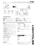
INSTRUCTION
INSTALLATION OF CALCULITE REFLECTOR TRIMS
INSTRUCTION SHEET FOR ITEMS:
A7053, A7701, A7058, B7054, B7705, B7760, B7780, C7055, C7709, D7707
READ AND UNDERSTAND
THESE INSTRUCTIONS
BEFORE lNSIALLING
This fixture is intended for installation
in accordance with the National
electrical shock, turn off electricity at fuse box before proceeding.
Retain these instructions for maintenance
reference.
g
FIXTURE.
Code and local or federal code specifications.
To prevent
m
FIG. 2
A. FRAME.IN
WIRING
IS:A7053
0888
4?’’’’”
FIG. 1
WARNING+RISK
Electrical
SHEET NO.
FIG. 3
C. PUSH.IN
B. SNAP.IN
OF FIRE) DO NOT INSTALL INSULATION
COMPARTMENT,
NOR ABOVE FIXTURE
WITHIN 3 INCHES OF FIXTURE SIDES OR
IN SUCH A MANNER SO AS TO ENTRAP HEAT.
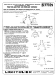
A. FRAME-IN (FIG. 1)
See Frame-In-Kit Instruction
installation
procedure.
Sheet (No. IS:A400) for
opl,:,&
B.SNAFIN (FIG. 2)
NOTE:For Overlapping
—
Trim installation
slip WHITE
TRIM RING on over OPTICAL SECTION, as shown on
Fig. 4 and 5, before Snap-in. For Flangeless Trim
installation, WHITE TRIM RING is not required.
Fasten ADJUSTABLE SOCKET HOUSING to OPTICAL
SECTION (reflector or baffle by: (1) aligning the
SPRING with CUTOUT on top (Fig. 6); (2) pushing
ADJUSTABLE SOCKET HOUSING onto OPTICAL
SECTION for engagement.
If S.LOTS are provided on
OPTICAL SECTION for vertical adjustment, engage
SPRING to desired Iamplwattage
position (see label
on inside and outside to neck of
REFLECTOR/HOUSING).
See Fig. 6 and 7.
SECTION
“Q
FIG. 4
FIG. 5
m
\
/
N
CUT OUT
TOP
LAM PIWATTAGE
POSITION LABEL
(INSIDE NECK)
LAM P/WATTAGE
POSITION LABEL
(OUTSIDE NECK)
FIG. 6
C. PUSH-IN (FIG. 3)
Push OPTICAL SECTION straight up into
MOUNTING FRAME until tight against finished
ceiling. RETAINING SPRINGS on MOUNTING
FRAME (Fig. 1) will secure OPTICAL SECTON
(reflector or baffle) in place.
NOTE: To remove OPTICAL SECTION, use FINGER
HOLE (Fig. 7) provided on upper part for sure grip;
turn OPTICAL SECTION counterclockwise
while
pulling downward. After starting, use both hands
to remove. See Fig. 8.
CARE AND MAINTENANCE OF “A12AK” REFLECTOR
If handling of reflectors with anodized or Alzak finish is
required, the use of clean white or plastic film gloves is
recommended
to avoid fingerprints.
:edzeg
or Alzak surfaces
can be cleaned
SPRINGS
TO REMOVE
by the following
1. Wipe of with a soft, clean, dry, lint-free cloth.
2. Wipe off with a clean cloth dampened in mild detergent
solution. Rinse, then wipe dry with lint-free cloth or paper
towel.
3. Wipe off with a clean cloth dampened with a solution of
wetting agent and water (such as 2 oz. per gallon
“Pluronic L62-LF by Wyandotte Products), or a liquid wax
such as Glass Wax@. Then wipe dry. Avoid gritty cleaning
agents.
L
I
<H-n-c>
M
E
la”
FIG. 7
FIG. 8
W.
;V:::::L,N::EV::,
Pat. No. 4,039,822
E;A::::