1
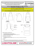
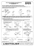
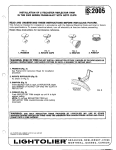
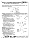
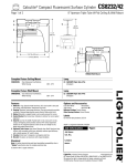
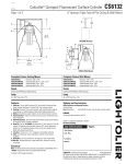
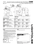
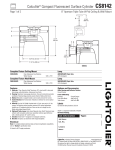
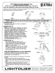
INSTRUCTION
IS:V611
IN=ALLATION
OF PRE-WIRED CALCULITE FRAME4N-KITS
A-LAMP WALL WASHERIDOWNLIGHT
INSTRUCTION SHE~
FOR ITEMS
V611, W612
READ
AND
UNDERSTAND
THESE INSTRUCTIONS
SHEET NO.
R0291
Page 1 of 2
BEFORE INSTALLING FIXTURE.
This fixture is intended for installation
in accordance with the National Electrical Code and local regulations. To assure full compliance
with local codes and regulations, check with your local electrical inspector before installation.
To prevent electrical shock, turn off
electricity at fuse box before proceeding.
Retain these Instructions for maintenance
reference.
DO
WARNING—(RISK
WIRING
OF FIREI DO NOT INSTALL InSUlatiOn
COMPARTMENT,
RELIXTOR/HOUSING
N~E
FRAME (Fig. 6).
NOR ABOVE FIXTURE
must be Installed
before closlng
WITHIN 3 INCHES OF FIXTURE SIDES OR
IN SUCH A MANNER SO AS TO ENTRAP HEAT.
in ceiling.
Make sum flnlshed
ceiling
Is lined up with MOUNTING
A. FRAME-IN AND WIRE-IN (FIG. 1)
1. Install FRAME-IN SECTION using ADJUSTABLE MOUNTING BRACKET (see below).
Wire to supply leads. White fixture lead to neutral supply lead. Black fixture lead to hot (120V.)
supply lead. Bare fixture wire to supply ground. Use wirenuts (local hardware items). Place all
electrical connections
in the J-BOX. Attach J-BOX COVER onto J-BOX.
s
[m
I
<>~”[~<>
1-[
1=
[~”
:&;~;;;;,N;~E&;~,E;~;y~~
nuea
I
Page 2 of 2
INSTALLATION OF PRE-WIRED CALCULITE FRAME-IN-KITS
A-LAMP WALL WASHER/DOWNLIGHT
(Cent’d)
B. ADJUST MOUNTING FRAME
For both plaster or other dry ceiling installation,
MOUNTING FRAME must be set so that the
bottom edge is flush with the finished ceiling, as
shown on Fig. 6.
NOTE:
1. To insure proper installation, the MOUNTING FRAME
must always” be” secure to structural ceiling members.
2. Final vertical adjustment can be made by means of
MOUNTING BRACKET SCREWS (Fig. 2) on inside of
MOUNTING FRAME.
c. ADJUST
FIG. 6
SOCKET HOUSING
Engage SPRING to SLOTS for desired lamp/wattage
position (see label on inside and outside of neck of
REFLECTOFUHOUSING as shown on Fig. 7).
ADJUSTABLE SOCKET
HOUSING
SLOT
NOTE: To remove REFLE(70R/HOUSING
for
inspection and maintenance, push
RETAINING SPRINGS outward and detach
REFLECTOR/HOUSING
from MOUNTING
FRAME (See Fig. 1).
To insure neat installation, do not remove
CARDBOARD PAINT SHIELD (provided) in
MOUNTING FRAME (Fig. 1). The SHIELD
will protect the inside of
REFLECTOR/HOUSING
from paint, pIaster
and dust. Remove it only after construction
is completed.
/
RETAINING
SPRINGS
FIG.
D. CARE AND MAINTENANCE
REFLECTOR
OF “Al-ZAK”
If handling of reflectors with anodized or Alzak
finish is required, the use of clean white or plastic
film gloves recommended
to avoid fingerprints.
Anodized
following
or Alzak surfaces
methods:
can be cleaned
by the
1. Wipe off with a soft, clean, dry, lint-free cloth.
2. Wipe off with a soft clean cloth dampened in
mild detergent solution. Rinse, then wipe dry with
lint-free cloth or paper towel.
3. Wipe off with a clean cloth dampened with a
solution of wetting agent and water (such as 2
oz. per gallon “Pluronic L62-LF” by Wyandotte
Products) or a liquid wax such as Glass Wax@.
Then wipe dry. Avoid gritty cleaning agents.
7