1
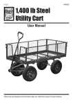
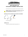
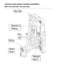
SEATED ROW SU50
ASSEMBLY INSTRUCTIONS
The Seated Row SU50 comes disassembled in two pieces. Follow the steps below to
assemble it.
TOOLS NEEDED
9/16”
socket wrench
9/16”
box wrench
7/8” open end
wrench or
crescent wrench
1 hr
15 min
45 min
30 min
ASSEMBLY TIME
One person can accomplish this assembly in approximately ½ hour.
UNPACKING AND PARTS
CAUTION: ASSEMBLING THE SEATED ROW SU50 REQUIRES THE ABILITY TO
MOVE HEAVY COMPONENTS. THE WEIGHT STACK SUBFRAME OF THE SU50 IS
LARGE AND HEAVY AND MAY CAUSE INJURY OR DEATH IF IT FALLS ON
SOMEONE. USE CAUTION WHEN ASSEMBLING THIS MACHINE.
1. Unpack the Weight Stack Subframe and the Seat Subframe from the crate. Stand
the Weight Stack Subframe up on its four feet. Stand the Seat Subframe up as shown in
Figure 1. Remove the cable and bolts pack.
M051-K50-A104
1
Seated Row SU50 Customer Assembly Instructions
Figure 1. Seated Row SU50.
1. Bolt holes on Seat
Subframe
½
0
2. Bolt holes on Weight
Stack Subframe
½
1
½
2
3. Cable Pulleys
½
3
4. Cable
½
4
½
5
Figure 2. Configuration for bolts, end caps, washers and nuts.
2
6
Seated Row SU50 Customer Assembly Instructions
INCLUDED PARTS
Included parts are:
1. 3-3/4” Hex head bolts (4)
2. End caps (bolt covers) (8)
3. Flat washer (used to “shorten” bolt so end cap will fit on the nut) (4)
4. End cap washers (end caps snap onto them) (8)
5. 3/8” Locknut (4)
6. Cable (1)
7. Row handle (1)
8. Handle clip (1)
ASSEMBLING THE SU50
1. Line up the Weight Stack Subframe and the Seat Subframe sections. Line up the
boltholes in the two sections.
Figure 3. Lined up sections of the Seated Row SU50.
2. Insert the bolts with flat washers and end cap washers at the head. Slide the flat
head washers onto the four bolts and insert the bolts into the Seat Subframe section of
the SU50. The flat washers will “shorten” the bolt so that the end caps will fit onto the nut
end of the bolt. Figure 4 shows the inserted bolt from the Seat Subframe side of the
SU50.
3
Seated Row SU50 Customer Assembly Instructions
Figure 4. Bolt (viewed from the Seat Subframe section).
3. Tighten the nuts. Moving to the Weight Stack Subframe side of the SU50, place end cap
washers and nuts onto the four bolt ends. Tighten the nuts so that they are completely
over the threads of the bolt (upper bolt in Figure 5). When all the bolts are tight, snap the
end cap covers onto both sides of the bolts. An end cap washer is shown in the lower part
of Figure 5.
Figure 5. Nuts, end cap washers and end caps on the bolts.
4
Seated Row SU50 Customer Assembly Instructions
INSTALLLING THE CABLE
1. Remove the pulleys. Once the Weight Stack Subframe is bolted to the Seat Subframe
section, you will need to remove the upper and lower pulleys to insert the cable. Using two
9/16” socket or box wrenches, remove the pulley bolts as shown in Figure 6. Set aside the
pulleys, end cap washers and bolt. Pulleys are shown as numbers 1 and 2 in Figure 7.
Figure 6. Removing the pulley bolt.
Figure 7. Upper and lower pulleys.
5
Seated Row SU50 Customer Assembly Instructions
2. Bolt the cable to the weight stack. Thread the 7/8” nut up on the cable bolt as shown in
Figure 7. Screw the bolt down into the weight stack as shown in Figure 8. Tighten the bolt
with a crescent wrench or 7/8” open-end wrench.
Figure 7. Thread the nut onto the cable.
Figure 8. Screw the cable into the weight stack.
3. Align the cable in the pulley housings. From the weight stack, run the cable through
the upper section of the upper pulley (#1 in Figure 9). Align the cable into the pulley
groove and reinstall the pulley bolt. Run the cable through the lower section of the lower
pulley (#2 in Figure 9). Align the cable into the pulley groove and reinstall the pulley bolt.
Make sure you install the cable ABOVE the small bolt at the bottom of the housing.
6
Seated Row SU50 Customer Assembly Instructions
Figure 9. Cable installation.
4. Reinsert the pulleys into the pulley housings and tighten the bolts. Replace the
bolts, end cap washers, and end caps using the configuration shown in Figure 10.
Figure 10. Pulley bolt assembly configuration.
5. Attach the handle and clip to the cable.
7