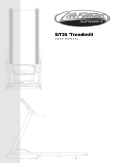
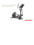
1
UT4 and RT4 Exercise Bikes U S E R M A N U A L CORPORATE HEADQUARTERS 10601 West Belmont Avenue Franklin Park, Illinois 60131 U.S.A. 847.288.3300 FAX: 847.288.3703 800.735.3867 (Toll-free within U.S.A., Canada) www.lifefitness.com INTERNATIONAL OFFICES LIFE FITNESS ASIA PACIFIC LTD Room 2610, Miramar Tower 132 Nathan Road Tsimshatsui, Kowloon HONG KONG Telephone: (+852) 2891.6677 FAX: (+852) 2575.6001 LIFE FITNESS ATLANTIC BV LIFE FITNESS BENELUX Bijdorpplein 25-31 2992 LB Barendrecht THE NETHERLANDS Telephone: (+31) 180.646.666 FAX: (+31) 180.646.699 Telephone: (+32) 87.300.942 FAX: (+32) 87.300.943 LIFE FITNESS DO BRAZIL Av. Dr. Dib Sauaia Neto 1478 Alphaville, Barueri, SP 06465-140 BRAZIL Telephone (+55) 11.4193.8282 FAX: (+55) 11.4193.8283 LIFE FITNESS VERTRIEBS GMBH Dückegasse 7-9/3/36 1220 Vienna AUSTRIA Telephone: (+43) 1.61 57 198 FAX: (+43) 1.61 57 198.20 LIFE FITNESS IBERIA Pol. Ind. Molí dels Frares. c/C, nº 12 08620 Sant Vicenç dels Horts (Barcelona) SPAIN Telephone: (+34) 93.672.4660 FAX: (+34) 93.672.4670 LIFE FITNESS EUROPE GMBH Siemensstrasse 3 85716 Unterschleissheim GERMANY Telephone: (+49) 89.31 77 51.0 FAX: (+49) 89.31 77 51.99 LIFE FITNESS ITALIA S.R.L. Via Vittorio Veneto, 57/A 39042 Bressanone (Bolzano) ITALY Telephone: (+39) 0472.835 470 FAX: (+39) 0472.833 150 LIFE FITNESS LATIN AMERICA and CARIBBEAN 10601 West Belmont Avenue Franklin Park, Illinois 60131 U.S.A. Telephone: (+1) 847.288.3300 FAX:(+1) 847.288.3886 LIFE FITNESS UK LTD Queen Adelaide Ely, Cambs CB7 4UB UNITED KINGDOM Telephone: (+44) 1353.666017 FAX: (+44) 1353.666018 LIFE FITNESS JAPAN Nippon Brunswick Bldg., #8F 5-27-7 Sendagaya Shibuya-Ku, Tokyo JAPAN 151-0051 Telephone: (+81) 3.3359.4309 FAX: (+81) 3.3359.4307 M051-00K63-A017 9/02 1 Before using this product, it is essential to read this ENTIRE operation manual and ALL installation instructions. This will help in setting up the equipment quickly and in instructing others on how to use it correctly and safely. FCC Warning - Possible Radio / Television Interference NOTE: This equipment has been tested and found to comply with the limits for a Class B digital device, pursuant to part 15 of the FCC rules. These limits are designed to provide reasonable protection against harmful interference in a residential installation. This equipment generates, uses and can radiate radio frequency energy, and if not installed and used in accordance with the operation manual, may cause harmful interference to radio communications. However, there is no guarantee that the interference will not occur in a particular installation. If this equipment does cause harmful interference to radio or television reception, which can be determined by turning the equipment off and on, the user is encouraged to try to correct the interference by one or more of the following measures: Reorient or relocate the receiving antenna. Increase the separation between the equipment and the receiver. Connect the equipment into an outlet on a circuit different from that to which the receiver is connected. Consult the dealer or an experienced radio/TV technician for help. Class HB (Home): Domestic use. Not suitable for therapeutic purposes. CAUTION: Any changes or modifications to this equipment could void the product warranty. Any service, other than cleaning or user maintenance, must be performed by an authorized service representative. There are no user-serviceable parts. 2 TABLE OF CONTENTS Unpacking and Assembly . . . . . . . . . . . . . . . . . . . . . . . . . . . . . . . . . . . . . . . . . . . . . . . . . . . . . . . . . . . . . . . . . . . .4 Operation . . . . . . . . . . . . . . . . . . . . . . . . . . . . . . . . . . . . . . . . . . . . . . . . . . . . . . . . . . . . . . . . . . . . . . . . . . . . . . . . .8 1. Getting Started . . . . . . . . . . . . . . . . . . . . . . . . . . . . . . . . . . . . . . . . . . . . . . . . . . . . . . . . . . . . . . . . . . . . .9 1.1 Important Safety Instructions . . . . . . . . . . . . . . . . . . . . . . . . . . . . . . . . . . . . . . . . . . . . . . . . . . . . . . . . . .9 1.2 Set-up . . . . . . . . . . . . . . . . . . . . . . . . . . . . . . . . . . . . . . . . . . . . . . . . . . . . . . . . . . . . . . . . . . . . . . . . . .10 Where to Place the Exercise Bike // How to Stabilize the Exercise Bike // How to Adjust the Seat // How to Adjust the Pedal Straps // Starting Up the Bike 2 The Display Console . . . . . . . . . . . . . . . . . . . . . . . . . . . . . . . . . . . . . . . . . . . . . . . . . . . . . . . . . . . . . . . .12 2.1 The Display Console Overview . . . . . . . . . . . . . . . . . . . . . . . . . . . . . . . . . . . . . . . . . . . . . . . . . . . . . . . .12 2.2 Display Console Descriptions . . . . . . . . . . . . . . . . . . . . . . . . . . . . . . . . . . . . . . . . . . . . . . . . . . . . . . . . .13 2.3 The Water Bottle Holder and Reading Rack . . . . . . . . . . . . . . . . . . . . . . . . . . . . . . . . . . . . . . . . . . . . . .14 3 The Workouts . . . . . . . . . . . . . . . . . . . . . . . . . . . . . . . . . . . . . . . . . . . . . . . . . . . . . . . . . . . . . . . . . . . . .15 3.1 Workout Overviews . . . . . . . . . . . . . . . . . . . . . . . . . . . . . . . . . . . . . . . . . . . . . . . . . . . . . . . . . . . . . . . . .15 3.2 Setting Up and Using the Workouts . . . . . . . . . . . . . . . . . . . . . . . . . . . . . . . . . . . . . . . . . . . . . . . . . . . . .15 Selecting and Using Quick Start Manual Mode // Selecting a Workout // Entering a Duration // Selecting and Adjusting the Intensity Level // Starting a Workout // Pausing a Workout // Resetting a Workout // Reviewing a Completed Workout // Using the Heart Rate Zone to Maximize Workout Benefits 3.3 Workout Descriptions . . . . . . . . . . . . . . . . . . . . . . . . . . . . . . . . . . . . . . . . . . . . . . . . . . . . . . . . . . . . . . . . . . . . .17 4 Service and Technical Data . . . . . . . . . . . . . . . . . . . . . . . . . . . . . . . . . . . . . . . . . . . . . . . . . . . . . . . . . . .19 4.1 Preventative Maintenance Tips . . . . . . . . . . . . . . . . . . . . . . . . . . . . . . . . . . . . . . . . . . . . . . . . . . . . . . . .19 4.2 Preventative Maintenance Schedule . . . . . . . . . . . . . . . . . . . . . . . . . . . . . . . . . . . . . . . . . . . . . . . . . . . .20 4.3 How to Obtain Product Service . . . . . . . . . . . . . . . . . . . . . . . . . . . . . . . . . . . . . . . . . . . . . . . . . . . . . . . .20 5 Specifications . . . . . . . . . . . . . . . . . . . . . . . . . . . . . . . . . . . . . . . . . . . . . . . . . . . . . . . . . . . . . . . . . . . . .21 5.1 Upright Exercise Bike Specifications . . . . . . . . . . . . . . . . . . . . . . . . . . . . . . . . . . . . . . . . . . . . . . . . . . . .21 5.2 Recumbent Exercise Bike Specifications . . . . . . . . . . . . . . . . . . . . . . . . . . . . . . . . . . . . . . . . . . . . . . . . .22 © 2002 Life Fitness, a division of Brunswick Corporation. All rights reserved. Life Fitness is a registered trademark of Brunswick Corporation. Essential is a trademark of Brunswick Corporation. Any use of these trademark, without the express written consent of Life Fitness is forbidden. 3 UNPACKING THE UPRIGHT EXERCISE BIKE 1. Carefully cut and remove the SHIPPING BANDS. 2. Carefully cut the tape securing the TOP FLAPS. 3. Fold the TOP FLAPS outward fully. 4. With the help of another person, remove the TOP SHIPPING TRAY. CAUTION: SOME PARTS EXTEND THROUGH THE BOTTOM OF THE TOP SHIPPING TRAY. BE CAREFUL NOT TO DAMAGE THE PARTS WHEN LIFTING THE TOP SHIPPING TRAY FROM THE SHIPPING CARTON. 5. Remove the DISPLAY CONSOLE carton and the HANDLEBAR ASSEMBLY from beside the BASE UNIT. 6. With the help of another person, lift the BASE UNIT from the SHIPPING CARTON. Remove the protective packaging from the unit. 4 ASSEMBLING THE UPRIGHT EXERCISE BIKE Tools Required: Metric Wrench Set, Metric Allen Wrench Set, Phillips Screwdriver 1. Locate and install the two LEVELER FEET (A) to the bottom of the REAR STABILIZER (B). 2. Attach the REAR STABILIZER (B) to the BASE UNIT (C) using two 2-3/8" BUTTON HEAD SCREWS (1) from the top of the REAR STABILIZER BRACKET (D) and two 13/16" BUTTON HEAD SCREWS (2) from the front side of the REAR STABILIZER BRACKET. Tighten the SCREWS securely. 3. Locate the MONOCOLUMN (E). Insert the WIRE (F) leading from the SIDE ACCESS HOLE (G) of the MONOCOLUMN fully into the MONOCOLUMN. Remove the GROMMET (H) from the SIDE ACCESS HOLE and set it aside. 4. Slide the MONOCOLUMN COVER (J) onto the MONOCOLUMN (E) as shown. Slide the MONOCOLUMN COVER up to the HANDLEBAR TUBE (K). 5. Re-insert the GROMMET (H) into the SIDE ACCESS HOLE (G) of the MONOCOLUMN (E). Pull the WIRE (F) back out through the SIDE ACCESS HOLE. 6. With the HANDLEBAR TUBE (K) facing the rear of the unit as shown, slide the MONOCOLUMN (E) into the MONOCOLUMN BRACKET (L) of the BASE UNIT (C). Slide the MONOCOLUMN down until it is fully seated. Secure the MONOCOLUMN to the MONOCOLUMN BRACKET using two 3-15/16" HEX HEAD BOLTS (3) and three LOCK WASHERS (4) (as shown) from the rear side of the MONOCOLUMN and two 2-3/8" HEX HEAD BOLTS (5) and LOCK WASHERS (4) from the user left side of the MONOCOLUMN BRACKET. Tighten the BOLTS securely. CAUTION: BE CAREFUL NOT TO PINCH THE WIRE (M) LEADING FROM THE MONOCOLUMN BRACKET (L) WHEN INSERTING THE MONOCOLUMN (E) INTO THE MONOCOLUMN BRACKET. 7. Connect the WIRE (M) leading from the MONOCOLUMN BRACKET (L) to the corresponding WIRE (F) from the SIDE ACCESS HOLE (G) of the MONOCOLUMN (E). Slide the MONOCOLUMN COVER (J) downward to the meet the MAIN SHROUDS (N). Secure the MONOCOLUMN COVER to the MAIN SHROUDS using four 1/2" PHILLIPS SCREWS (6) and matching FLAT WASHERS (7). Tighten the SCREWS securely. Do not overtighten the SCREWS. 10. With the nose of the SEAT (P) facing forward, insert the SEAT POST (Q) into the SEAT POST SUPPORT (S). 11. Begin inserting the SEAT ADJUSTMENT KNOB (T). Lift upward on the seat and seat post until the seat post locks into a position. Insert the 5/16" PHILLIPS LOCKING SCREW (9) and tighten securely. 12. Slide the SEAT POST CAP (O) downward to meet the top of the SEAT POST SUPPORT (S). Secure the SEAT POST CAP to the SEAT POST SUPPORT using two 1/2" PHILLIPS SCREWS (6). Tighten the SCREWS securely. Do not overtighten the SCREWS. 13. Remove the DISPLAY CONSOLE (U) from its shipping carton. Position the above the DISPLAY CONSOLE BRACKET (V). Connect the CONNECTOR (W) leading from the DISPLAY CONSOLE BRACKET to the corresponding jack located on the back of the DISPLAY CONSOLE. Secure the DISPLAY CONSOLE to the DISPLAY CONSOLE BRACKET using four 1/2" PHILLIPS SCREWS (6). Tighten the SCREWS securely. Do not overtighten the SCREWS. 14. Locate the HANDLEBAR ASSEMBLY (X). With the handlebars facing forward, position the HANDLEBAR ASSEMBLY near the top of the HANDLEBAR TUBE (K). Slide the HANDLEBAR ASSEMBLY fully into the HANDLEBAR TUBE. Secure the HANDLEBAR ASSEMBLY to the HANDLEBAR TUBE using four 5/8" BUTTON HEAD SCREWS (10) and matching FLAT WASHERS (11). Tighten the SCREWS securely. 15. Locate the PEDALS. Install the RIGHT PEDAL (Y) (marked with an "R") to the USER RIGHT CRANK ARM (Z). Repeat for the LEFT PEDAL (AA) (marked with an "L"). NOTE: THE LEFT PEDAL (Y) HAS REVERSE THREADS. 16. Locate the WATER BOTTLE BRACKET (BB). Secure the WATER BOTTLE BRACKET to the underside of the HANDLEBAR TUBE (K) using two 3/8" PHILLIPS SCREWS (12). Tighten the screws securely. Insert the WATER BOTTLE (CC) into the WATER BOTTLE BRACKET. 17. Position the unit in the desired location for use. The unit can be easily moved into place by lifting the rear of the unit and rolling it on the front rollers. Level the unit before use. Refer to the leveling instructions stated in the operations portion of this manual. 8. Locate the SEAT POST CAP (O). With the curved side facing upward toward the SEAT (P), slide the SEAT POST CAP over the SEAT POST (Q). 9. Locate and slide the SEAT POST SPACER (R) over the end of the SEAT POST (Q). Using two 1/4" PHILLIPS SCREWS (8), secure the SEAT POST SPACER to the end of the SEAT POST. Tighten the SCREWS securely. 5 UNPACKING THE RECUMBENT EXERCISE BIKE 1. Carefully cut and remove the SHIPPING BANDS. 2. Carefully cut the tape securing the TOP FLAPS. 3. Fold the TOP FLAPS outward fully. 4. With the help of another person, remove the SIDE SHIPPING TRAY. CAUTION: BE SURE TO KEEP THE LEFT AND RIGHT SIDES OF THE SIDE SHIPPING TRAY TOGETHER WHILE REMOVING IT FROM THE SHIPPING CARTON. 5. Remove the DISPLAY CONSOLE carton and the ACCESSORY TRAY from beside the BASE UNIT. 6. With the help of another person, lift the BASE UNIT from the SHIPPING CARTON. Remove the protective packaging from the unit. 6 ASSEMBLING THE RECUMBENT EXERCISE BIKE 12. Re-insert the GROMMET (R) into the SIDE ACCESS HOLE (Q) of the MONOCOLUMN (O). Pull the WIRE (P) back out through the SIDE ACCESS HOLE. Tools Required: Metric Wrench Set, Metric Allen Wrench Set, Phillips Screwdriver 13. With the HANDLEBAR TUBE (T) facing the rear of the unit as shown, slide the MONOCOLUMN (O) into the MONOCOLUMN BRACKET (U) of the BASE UNIT (C). Slide the MONOCOLUMN down until it is fully seated. Secure the MONOCOLUMN to the MONOCOLUMN BRACKET using two 3-15/16" HEX HEAD BOLTS (13) and three LOCK WASHERS (14) (as shown) from the front side of the MONOCOLUMN and two 2-3/8" HEX HEAD BOLTS (15) and LOCK WASHERS (14) from the user left side of the MONOCOLUMN BRACKET. Tighten the BOLTS securely. 1. 1. Locate and install the two LEVELER FEET (A) to the bottom of the REAR STABILIZER (B). 2. Attach the REAR STABILIZER (B) to the BASE UNIT (C) using two 2-3/8" BUTTON HEAD SCREWS (1) from the top of the REAR STABILIZER BRACKET (D) and two 13/16" BUTTON HEAD SCREWS (2) from the front side of the REAR STABILIZER BRACKET. Tighten the SCREWS securely. 3. Locate the HANDLEBAR ASSEMBLY (E) and the SEAT ASSEMBLY (F). With the handlebars facing upward and forward, align the mounting holes of the HANDLEBAR ASSEMBLY with those in the SEAT ASSEMBLY. Secure the HANDLEBAR ASSEMBLY to the SEAT ASSEMBLY using four 5/8" BUTTON HEAD SCREWS (3) and FLAT WASHERS (4). Tighten the SCREWS securely. 4. Locate the SEAT BOTTOM (G). Align the SEAT BOTTOM mounting holes with those in the LOWER SEAT SUPPORT TUBES (H). Secure the SEAT BOTTOM using four 2" PHILLIPS SCREWS (5) and LOCK WASHERS (6). Tighten the SCREWS securely. 5. Align the guide rollers located on the underside of the SEAT ASSEMBLY (F) with the SEAT EXTRUSION (J). Carefully guide the SEAT ASSEMBLY onto the SEAT EXTRUSION. Slide the SEAT ASSEMBLY fully forward. CAUTION: BE CAREFUL NOT TO PINCH THE WIRE (V) LEADING FROM THE MONOCOLUMN BRACKET (U) WHEN INSERTING THE MONOCOLUMN (O) INTO THE MONOCOLUMN BRACKET. 14. Connect the WIRE (V) leading from the MONOCOLUMN BRACKET (U) to the corresponding WIRE (P) from the SIDE ACCESS HOLE (Q) of the MONOCOLUMN (O). Slide the MONOCOLUMN COVER (S) downward to the meet the MAIN SHROUDS (W). Secure the MONOCOLUMN COVER to the MAIN SHROUDS using four 1/2" PHILLIPS SCREWS (12) and matching FLAT WASHERS (6). Tighten the SCREWS securely. Do not overtighten the SCREWS. 6. In the hole located in the user right side of the SEAT EXTRUSION (J), behind SEAT ASSEMBLY (F), install one 1-3/8" BUTTON HEAD SCREW with locktite (7), one 15/16" FLAT WASHER (8), and one 1" RUBBER BUMPER (9) as shown. 15. Remove the DISPLAY CONSOLE (X) from its shipping carton. Position the above the DISPLAY CONSOLE BRACKET (Y). Connect the WIRE (Z) leading from the DISPLAY CONSOLE BRACKET to the corresponding JACK(s) located on the back of the DISPLAY CONSOLE. Secure the DISPLAY CONSOLE to the DISPLAY CONSOLE BRACKET using four 1/2" PHILLIPS SCREWS (12). Tighten the SCREWS securely. Do not overtighten the SCREWS. 7. Mount the SEAT ADJUSTMENT LEVER (K) to the user right side of the SEAT ASSEMBLY (F) using two 3/4" PHILLIPS SCREWS (10) and LOCK WASHERS (11). Tighten the SCREWS securely. 16. Locate the PEDALS. Install the RIGHT PEDAL (AA) (marked with an "R") to the USER RIGHT CRANK ARM (BB). Repeat for the LEFT PEDAL (CC) (marked with an "L"). 8. Secure the SEAT BACK (L) to the UPPER SEAT SUPPORT TUBES (M) using four 2" PHILLIPS SCREWS (5) and LOCK WASHERS (6). Tighten the SCREWS securely. 9. Locate the SEAT EXTRUSION ENDCAP (N). Secure the SEAT EXTRUSION ENDCAP to the SEAT EXTRUSION (J) using two 1/2" PHILLIPS SCREWS (12). 10. Locate the MONOCOLUMN (O). Insert the WIRE (P) leading from the SIDE ACCESS HOLE (Q) of the MONOCOLUMN fully into the MONOCOLUMN. Remove the GROMMET (R) from the SIDE ACCESS HOLE and set it aside. 11. Slide the MONOCOLUMN COVER (S) onto the MONOCOLUMN (O) as shown. Slide the MONOCOLUMN COVER up to the HANDLEBAR TUBE (T). NOTE: THE LEFT PEDAL (CC) HAS REVERSE THREADS. 17. Locate the WATER BOTTLE BRACKET (DD). Secure the WATER BOTTLE BRACKET to the underside of the MONOCOLUMN (O) using two 3/8" PHILLIPS SCREWS (16). Tighten the screws securely. Insert the WATER BOTTLE (EE) into the WATER BOTTLE BRACKET. 18. Position the unit in the desired location for use. The unit can be easily moved into place by lifting the rear of the unit and rolling it on the front rollers. Level the unit before use. Refer to the leveling instructions stated in the operations portion of this manual. 7 This Operation Manual describes the functions of the following products: EssentialTM upright exercise bike: UT4 Essential recumbent exercise bike: RT4 See Section 5, titled Specifications page in this manual for product-specific features. Statement of Purpose: The exercise bike is a machine that simulates the movements of riding a bicycle at various speeds and levels of resistance. Health-related injuries may result from incorrect or excessive use of exercise equipment. The manufacturer STRONGLY recommends seeing a physician for a complete medical exam before undertaking an exercise program, particularly if the user has a family history of high blood pressure or heart disease; or is over the age of 45; or smokes, has high cholesterol, is obese, or has not exercised regularly in the past year. The manufacturer also recommends consulting a fitness professional on the correct use of this product. If, at any time while exercising, the user experiences faintness, dizziness, pain, or shortness of breath, he or she must stop immediately. 8 1 1.1 GETTING STARTED IMPORTANT SAFETY INSTRUCTIONS SAFETY WARNING: The safety of the product can be maintained only if it is examined regularly for damage and wear. See Preventative Maintenance section for details. Before using this product, it is essential to read this ENTIRE operation manual and ALL instructions. The exercise bike is intended for use solely in the manner described in this manual. Always follow the console instructions for proper operation. Close supervision is necessary when used by or near children, invalids or disabled persons. If an exercise bike does not function properly after it has been dropped, damaged, or even partially immersed in water, contact Customer Support Services for assistance. Never insert objects into any opening in the exercise bike. If an object should drop inside, carefully retrieve it. If the item is beyond reach, contact Customer Support Services. Never place liquids of any type directly on the unit, except in an accessory tray. Containers with lids are recommended. Do not use the exercise bike outdoors, near swimming pools or in areas of high humidity. Keep all loose clothing, shoelaces, and towels away from the exercise bike pedals. Keep the area around the exercise bike clear of any obstructions, including walls and furniture. Always be careful and exercise caution when mounting or dismounting the exercise bike. Use the handlebar whenever additional stability is required. Wear shoes with rubber or high-traction soles. Do not use shoes with heels, leather soles, cleats or spikes. Do not use the bike in bare feet. Do not tip the exercise bike on its side during operation. Keep hands and feet away from all moving parts. To ensure proper functioning of this product, do not install attachments or accessories that are not provided or recommended by Life Fitness. Use this product in a well-ventillated area. Use this product on a solid, level surface. Make sure that all components are fastened securely. These include the seat post, saddle, handlebars, and pedals. SAVE THESE INSTRUCTIONS FOR FUTURE REFERENCE. 9 1.2 SETUP Read the entire Operation Manual before setting up the exercise bike. WHERE TO PLACE THE EXERCISE BIKE Following all safety instructions in Section 1.1, move the bike to the location in which it will be used. See Section 7, titled Specifications, for the dimensions of the footprint. Allow a distance of four feet, or 120 centimeters, between the bike and other objects or surfaces on either side. HOW TO STABILIZE THE EXERCISE BIKE After placing the bike in position, check the unit's stability by attempting to rock it in all directions. Any slight rocking indicates that the unit must be leveled. Determine which foot is not resting completely on the floor. Loosen the jam nut with an open-end 17mm wrench, and rotate the stabilizing foot to lower it. Verify that the bike is stable, and repeat the adjustment as necessary until the unit no longer rocks. Lock the adjustment by tightening the jam nut against the stabilizer bar. HOW TO ADJUST THE SEAT Proper seat positioning minimizes unecessary leg muscle fatigue. To determine whether or not the seat requires adjustment, sit on it and place the balls of the feet on the pedals. The knee should bend slightly when the pedal is at the furthest point in its rotation, relative to the body. The user should be able to pedal without locking the knees or shifting in the seat. Adjusting the seat on the upright bike: The bike post features a vertical locking pin seat adjustment system, which makes it easy and safe to change the height of the seat quickly. To raise the seat, first get off the bike. Hold the seat, turn the spring-loaded knob on the right of the seat post once counterclockwise to loosen it, and pull out the knob to unlock the post from its present position. Pull the seat upward to the desired height, and release the knob to let it lock into place. Turn the knob once clockwise to tighten it. Test and re-adjust the seat height as necessary. To lower the seat, first get off the bike. Hold the seat, turn the spring-loaded knob on the right of the seat post once counterclockwise to loosen it, and pull out the knob to unlock the post from its present position. Let the seat slide down to the desired height, and release the knob to let it lock into place. Turn the knob once clockwise to tighten it. Test and re-adjust the seat height as necessary. CAUTION: When using the height adjustment mechanism to change the height of a partially raised seat, hold the seat to prevent it from falling on the hand. 10 Adjusting the seat on the recumbent bike: Lift the spring-loaded adjusting handle located on the right side of the seat. Slide the seat forward or backward as necessary to the proper position and release the handle to complete engagement. Gently rock the seat forward and backward to ensure that it is locked into place. Check the seat distance again and readjust it if necessary. Note: If the seat carriage rocks excessively, use a wrench to loosen the jam nut (A) on either side of the seat carriage. With another wrench, tighten the adjustment roller on the inside of the carriage until it is snug, but do not over-tighten it. Then, while holding the roller in place, tighten the lock nut. Repeat the procedure for the other side of the seat carriage. CAUTION: Do not attempt to adjust the seat while pedaling the bike. Doing so, or failing to insert the seat pin completely may result in an uncomfortable workout or cause injury. HOW TO ADJUST THE PEDAL STRAPS The bike pedal safety straps keep the user's shoes on the pedals during a workout. The straps should fit comfortably, but they also should be tight enough to prevent shoes from slipping at any point in the pedaling rotation. Before working out, the user should test and adjust the tightness of the straps. The straps can be adjusted to fit a variety of shoe sizes. Each strap is held in place by a spring-loaded clip that is connected to the outer edge of each pedal. To tighten a strap, simply pull the loose end of the strap down. It automatically locks into place with each pull. To loosen a strap, press down on the top of the clip and pull the strap up. Release the clip to lock the strap into place. Test the adjustment, and change if necessary. STARTING UP THE BIKE See Section 7, titled Specifications, for power requirements. Insert the AC adapter into an electrical outlet that has been properly installed and grounded in accordance with all local codes and ordinances. To power up the exercise bike, simply start pedaling or press any key on the console. Once the units power is on, the console display lights up, making it possible to select a workout or to begin a MANUAL workout using QUICK START MANUAL MODE. See Section 4.2, titled the Using the Workouts, for more information. 11 2 2.1 THE DISPLAY CONSOLE DISPLAY CONSOLE OVERVIEW The computerized display console on the exercise bike allows the user to tailor a workout to personal fitness abilities and goals and to monitor progress. With this easy-to-use console the user can track fitness improvement from one workout to the next. 12 2.2 DISPLAY CONSOLE DESCRIPTIONS The functions for the keys and display windows on the exercise bike console are listed and described in this section. See Section 4, titled The Workouts, for detailed information on using the console to set up workouts. A START/STOP/HOLD TO PRESET: Use this key to initiate a number of different functions on the bike. Begining a 30-minute QUICK-START MANUAL workout immediately, without setup steps Beginning a workout after completing the setup steps for a specific workout Pausing a workout-in-progress Restarting a paused workout Deleting a current workout and making it possible to set up a new workout B ENTER: Press this key to accept information displayed by the console when setting up a workout. C ARROW KEYS: Use these keys when setting up a workout to change displayed values for workout type, duration, and resistance level. When a workout is in progress, use these keys to change the intensity level. D SCROLL: During a workout-in-progress, press this key to browse through workout statistics displayed in the bottom data window. Each time the SCROLL key is pressed, a different value is displayed, and its corresponding light emitting diode (LED) lights up simultaneously. When the Scan LED lights up, the lower DATA window automatically displays all statistics in rotating succession. Press this key to view summary data for a completed workout, including total calories burned and total distance traveled E DATA WINDOWS: Two data windows are set in the center of the console display. The top window shows the elapsed time of a workout-in-progress. During a workout setup, this window also shows the default duration of 30 minutes, which the user change using the ARROW keys. The bottom window displays the following statistics in an alternating rotation for a workout-in-progress. Depending on which statistic is being displayed at any given instance, the corresponding LED lights up at the same time. F RPM (Revolutions Per Minute): The pedaling speed or rate Distance: The total distance traveled Calories: The number of calories burned Level: The resistance level of the current interval of a workout-in-progress WORKOUT LED INDICATORS: One set of LEDs is matched to the bikes set of workout options. During a workout setup, each time the user presses an ARROW key to view another workout option, one of these LEDs lights up to indicate that the corresponding workout is the currently displayed option. While a workout-in-progress, the LED corresponding to that workout remains lit up. Another set of LEDs is matched to a set of workout statistics. See the DATA WINDOWS description above. The LED labeled scan lights up during a workout-in-progress to indicate that the console is alternately displaying RPM, Distance, Calories and Level in the bottom DATA WINDOW. See the SCROLL key and DATA WINDOW descriptions above for more information. G DOT MATRIX DISPLAY: This window displays a workouts profile, which consists of columns of light that represent the levels of intensity of each interval. During the setup for a RANDOM workout, this window displays computergenerated profile options, which the user can browse using the ARROW keys. 13 2.3 THE WATER BOTTLE HOLDER AND READING RACK A water bottle holder is mounted on the monocolumn of the bike. A reading rack for supporting a book or magazine is located at the base of the upper panel of the console. 14 3 3.1 THE WORKOUTS WORKOUT OVERVIEWS This section lists the exercise bikes pre-programmed workouts. For more detailed information, see Section 3.2, titled Setting Up and Using the Workouts. QUICK START MANUAL MODE is the fastest way to begin exercising, and it bypasses the steps involved in selecting a specific workout program. After the START key is pressed, a constant-level workout begins. The resistance level does not change automatically. INTERVAL combines hills and valleys of different resistance levels, which is proven to provide effective, time-efficient cardiovascular results. RANDOM is an interval training workout for which the user selects a computer-generated profile of varying intensity levels. MANUAL is a workout in which the resistance level does not change automatically. PEAK is intended to burn fat by building up to, and maintaining, a constant level of resistance throughout the workout. SLOPE gradually increases the intensity throughout the workout duration. It is intended to strengthen the heart, as well as the major muscle groups that are most active during the workout, such as the leg muscle groups. CHALLENGE begins at a high resistance level and maintains this level throughout the duration. 3.2 SETTING UP AND USING THE WORKOUTS To activate the console, press any key, or simply start pedaling. When the console display lights up, either select QUICK START MANUAL MODE, or select a specific workout. Setting up a specific workout involves three steps, which are described in this section: 1. Selecting a workout 2. Entering a workout duration 3. Selecting a difficulty level 4. Starting the workout (pressing START) SELECTING AND USING QUICK START MANUAL MODE Press the START key to begin a 30-minute MANUAL workout immediately. Once the workout is in progress, it is possible to change the resistance level using the ARROW keys. SELECTING A WORKOUT For INTERVAL, MANUAL, PEAK, SLOPE, and CHALLENGE: Press the ARROW KEYS until the LED display for the desired workout lights up. Then, press ENTER to confirm the workout selection. For RANDOM: Press the ARROW KEYS until the LED display for the RANDOM workout lights up. Then, press ENTER. The first computer-generated RANDOM workout profile appears in the the DOT MATRIX DISPLAY. To accept this profile, press ENTER. To view another profile, press an ARROW key. Continue to press the ARROW key until a desired profile appears. Then, press ENTER to accept the profile. ENTERING A DURATION After a workout is selected, the top DATA WINDOW flashes a default workout duration of 30 minutes. Press ENTER to accept the default. Or, to change the duration, use the ARROW keys. Then, when the desired duration appears in the DATA WINDOW, press ENTER to accept the duration. It is not possible to change the duration of a workout-in-progress. 15 SELECTING A DIFFICULTY LEVEL After a duration is entered, the bottom DATA WINDOW flashes a default difficulty level of 1, which is the easiest of the nine difficulty levels. Press ENTER to accept the default. Or, to change the level, use the ARROW keys. Then, when the desired level appears in the DATA WINDOW, press ENTER to accept the duration. Each of the nine difficulty levels corresponds to a range of resistance levels as seen in the table below. Resistance levels are applied to each individual interval within a workout profile. See Section 3.3, titled Workout Descriptions for more information. While the workout is in progress, it is possible to change the resistance level of the current interval. That change remains in effect for the duration of the interval. See the topic titled Adjusting the Intensity Level in this section. Difficulty Level 1 2 3 4 5 6 7 8 9 Resistance Level Range 1 to 8 2 to 9 3 to 10 4 to 11 5 to 12 6 to 13 7 to 14 8 to 15 9 to 16 STARTING A WORKOUT After accepting a difficulty level, press START to begin the workout. ADJUSTING THE RESISTANCE LEVEL OF AN INTERVAL The exercise bike features 16 resistance levels, with 1 being the easiest and 16 being the most difficult. While a workout is in progress, it is possible to change the resistance level of the current interval. To do so, simply press the UP or DOWN ARROW key repeatedly until the DATA DISPLAY window shows the desired level. That change remains in effect for the duration of the interval only. Note: With the exercise bikes braking resistance feature, the resistance level increases proportionally with the pedaling speed. PAUSING A WORKOUT To pause a workout-in-progress, press the STOP key, or simply stop pedaling for 25 seconds. A workout can remain in pause mode for a maximum duration of five minutes. If a paused workout is not resumed before the five-minute pause duration ends, the console shuts down, and the paused workout information is lost. To resume a paused workout, press the START key or simply begin pedaling again. RESETTING A WORKOUT To reset a workout, press the STOP key, and hold it for three seconds. This deletes the current workout and makes it possible to set up a new workout. REVIEWING A COMPLETED WORKOUT When a workout reaches the end of its duration, the console emits four consecutive beeps. At this point, it is possible to review summary data for the completed workout, includng total calories burned and distance traveled, by pressing the SCROLL key and reading the results in the DATA WINDOWS. Afterward, press the STOP key to return to the workout-select mode. 16 USING THE HEART RATE ZONE TO MAXIMIZE WORKOUT BENEFITS Research shows that keeping the heart rate within a certain range while exercising promotes muscular and cardiovascular conditioning for maximum health benefits. This range is between 60 percent and 85 percent of a given users theoretical maximum heart rate. The maximum rate varies by age. To calculate it, subtract the users age from the number 220. For example, the theoretical maximum heart rate for a 35-year-old user would be 185 beats per minute (bpm) because 220-35=185. Therefore, the optimal heart rate range or zone for a 35-year-old user would be between 111 bpm (185 x .60) and 157 bpm (185 x .85). NOTE: Consulting a fitness trainer is recommended for defining specific fitness goals and designing a workout program. To monitor the heart rate during a workout, feel the pulse in the wrist or the carotid artery in the neck while looking at a watch. Count the number of pulse beats within one minute. SWITCHING THE CONSOLE DISPLAY TO METRIC UNITS By default, the bikes console displays the workout statistic of distance in English units. It is possible to switch to metric units. When the console is shut down, remove the four screws that attach the console to the console support assembly column. Carefully turn the console upside down and flip the English/Metric switch that appears in the back of the console to the Metric setting. Re-attach the console to the support assembly column. Restart the bike. 3.3 WORKOUT DESCRIPTIONS INTERVAL This workout combines hills and valleys of alternating high- and low-resistance levels. Raising and decreasing the heart rate in this manner is proven to provide effective, time-efficient fitness results. Each interval is of equal duration, and the overall duration of the workout determines the duration of the intervals. As the profile diagram indicates, the workout begins with a low-resistance warm-up and ends with a low-resistance cool-down. RANDOM When the user selects a RANDOM workout, the bike computer automatically generates various profiles, each offering a different combination of resistance levels. This choice of profiles adds variety to the workout routine. 17 MANUAL MANUAL is a workout in which the resistance level does not change automatically. When a MANUAL workout is in progress, the user can vary the resistance levels by pressing the UP and DOWN ARROW keys. PEAK PEAK is intended to burn fat by maintaining a constant level of resistance throughout the workout. As the profile diagram indicates, the resistance level begins gradually, maintains a plateau and then gradually declines. SLOPE SLOPE gradually increases the intensity throughout the workout duration. It is intended to strengthen the heart, as well as the major muscle groups that are most active during the workout, such as the leg muscle groups. As the profile diagram indicates, the workout starts at a low resistance level, builds to a peak and and with a low-level cool-down interval. CHALLENGE CHALLENGE begins at a high resistance level and maintains this level throughout the duration. As the profile diagram indicates, the workout begins at a high level and continues for most of the duration at a high plateau. 18 4 4.1 SERVICE AND TECHNICAL DATA PREVENTATIVE MAINTENANCE TIPS The exercise bike is backed by engineering excellence and is one of the most rugged and trouble-free pieces of exercise equipment on the market today. The manufacturers products have proven to be durable in health clubs, colleges, military facilities, and other locations the world over. This same technology, engineering expertise, and reliability have gone into the exercise bike. NOTE: The safety of the equipment can be maintained only if the equipment is examined regularly for damage or wear. If maintenance is required, keep the equipment out of use until defective parts are repaired or replaced. Pay special attention to parts that are subject to wear as outlined in the Preventive Maintenance Schedule. The following preventive maintenance tips will keep the exercise bike operating at peak performance: Locate the exercise bike in a cool, dry place. Clean the top surface of the pedals regularly. Keep the display console free of fingerprints and salt build-up caused by sweat. Use a 100% cotton cloth, lightly moistened with water and mild liquid cleaning product, to clean the exercise bike. Other fabrics, including paper towels, may scratch the surface. Do not use ammonia or acid-based cleaners. Long fingernails may damage or scratch the surface of the console; use the pad of the finger to press the selection buttons on the console. Clean the housing thoroughly on a regular basis. NOTE: A non-abrasive cleaner and soft cotton cloth are strongly recommended for cleaning the exterior of the unit. At no time should cleaner be applied directly to any part of the equipment; apply the non-abrasive cleaner on a soft cloth, and then wipe the unit. 19 4.2 PREVENTATIVE MAINTENANCE SCHEDULE Follow the schedule below to ensure proper operation of the product. Follow the schedule below to ensure proper operation of the product. ITEM Display Console Console Mounting Bolts Accessory Tray Frame Plastic Covers Pedals and Straps WEEKLY C MONTHLY I BI-ANNUALLY ANNUALLY I C C C C I I I I KEY: C=Clean; I=Inspect 4.3 HOW TO OBTAIN PRODUCT SERVICE 1. Verify the symptom and review the operating instructions. The problem may be unfamiliarity with the product and its features and workouts. 2. Locate and document the serial number of the unit. The serial number plate is located on the front stabilizer, below the shroud. 3. Contact Customer Support Services via the Web at: www.lifefitness.com, or call the nearest Customer Support Services group: For Product Service within the United States and Canada: Telephone: (+1) 847.451.0036 FAX: (+1) 847.288.3702 Toll-free telephone: 800.351.3737 For Product Service Internationally: Life Fitness Europe GmbH Telephone: (+49) 089.317.751.66 FAX: (+49) 089.317.751.38 Life Fitness Asia Pacific Ltd Telephone: (+852) 2891.6677 FAX: (+852) 2575.6001 Life Fitness (UK) LTD Telephone: (+44) 1353.665507 FAX: (+44) 1353.666018 Life Fitness Latin America and Caribbean Telephone: (+1) 847.288.3964 FAX: (+1) 847 288.3886 Life Fitness Atlantic BV Life Fitness Benelux Telephone: (+32) 03.644.44.88 FAX: (+32) 03.644.24.80 Telephone: (+32) 87.300.942 FAX: (+32) 87.300.943 Life Fitness Italia S.R.L. Telephone: (+39) 0472.835.470 FAX: (+39) 0472.833.150 Toll-free telephone: 800.438836 Life Fitness Vertriebs GmbH Telephone: (+43) 1615.7198 FAX: (+43) 1615.7198.20 20 Life Fitness Brazil Telephone: (+55) 11.7295.2217 FAX: (+55) 11.7295.2218 Life Fitness Japan Telephone: (+81) 3.3359.4306 FAX: (+81) 3.3359.4307 Life Fitness Iberia Telephone : (+34) 93 672 4660 FAX : (+34) 93 672 4670 5 5.1 SPECIFICATIONS UPRIGHT EXERCISE BIKE SPECIFICATIONS Designed use: Maximum user weight: CONSOLE: Displays: Summaries: WORKOUTS: Intensity levels: Pedal size Drive type: Power requirements: Color: ASSEMBLED DIMENSIONS: Length Width Height Weight SHIPPING DIMENSIONS: Length Width Height Weight Consumer 300 pounds / 136 kilograms DATA DISPLAYS with time, RPM, distance, calories, and level DOT MATRIX WINDOW indicating workout profile Time, distance Quck Start Manual Mode, Interval, Random, Manual, Peak, Slope, Challenge 16 4.5 inches / 11.5 centimeters Poly-V belt-drive 120V in United States 220V in Europe 240+V in Australia Blue 41 inches / 104 centimeters 23.5 inches / 60 centimeters 56 inches / 142 centimeters 105 pounds / 47.6 kilograms 44.88 inches / 114 centimeters 17.91 inches / 45.5 centimeters 29.92 inches / 76 centimeters 122 pounds / 55.3 kilograms 21 5.2 RECUMBENT EXERCISE BIKE SPECIFICATIONS Designed use: Maximum user weight: CONSOLE: Displays: Summaries: WORKOUTS: Intensity levels: Pedal size Drive type: Power requirements: Color: ASSEMBLED DIMENSIONS: Length Width Height Weight SHIPPING DIMENSIONS: Length Width Height Weight 22 Consumer 300 pounds / 136 kilograms DATA DISPLAYS with time, RPM, distance, calories, and level DOT MATRIX WINDOW indicating workout profile Time, distance Quck Start Manual Mode, Interval, Random, Manual, Peak, Slope, Challenge 16 4.5 inches / 11.5 centimeters Poly-V belt-drive 120V in United States 220V in Europe 240+V in Australia Blue 56.5 inches / 143.5 centimeters 25.75 inches / 70.5 centimeters 50 inches / 127 centimeters 129.5 pounds / 58.7 kilograms 59.84 17.91 29.92 151.2 inches / 152 centimeters inches / 45.5 centimeters inches / 76 centimeters pounds / 68.6 kilograms