1
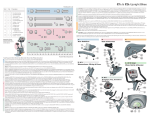
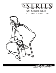
A S S E M B LY
INSTRUCTIONS
R1/ R 3 L I F E C Y C L E E X E R C I S E B I K E S
R
Life Fitness offers a full line of premier fitness equipment for the home.
®
TOTA L - B O D Y E L L I P T I C A L C R O S S -T R A I N E R S | T R E A D M I L L S | L I F E C Y C L E E X E R C I S E B I K E S
S TA I R C L I M B E R S | G Y M S Y S T E M S
5 1 0 0 N. R I V E R R O A D, S C H I L L E R PA R K , I L L I N O I S 6 0 1 7 6
LIFEFITNESS.COM
© 2006 Life Fitness, a division of Brunswick Corporation. All rights reserved. Life Fitness is a registered trademarks of Brunswick
Corporation. Any use of this trademark, without the express written consent of Life Fitness is forbidden. 8114701 Rev A-1 (07/06)
R1 & R3 Recumbent Bikes
Hardware List
Item
Qty
Description
1)
Slide the MONOCOLUMN (S) into the MONOCOLUMN BRACKET (Z). Slide the MONOCOLUMN down until it is fully seated. Secure the MONOCOLUMN to the MONOCOLUMN
BRACKET using two 100 mm HEX HEAD BOLTS (13) and three THICK FLAT WASHERS (14) (as shown) from the front side of the MONOCOLUMN and two 60 mm HEX HEAD BOLTS
(15) and THICK FLAT WASHERS (14) from the user left side of the MONOCOLUMN BRACKET. Tighten the BOLTS securely.
CAUTION: Be careful not to pinch the WIRE(s) (AA) leading from the MONOCOLUMN BRACKET (Z) when inserting the MONOCOLUMN (S) into the MONOCOLUMN BRACKET.
Connect the WIRE(s) (AA) leading from the MONOCOLUMN BRACKET (Z) to the corresponding WIRE (W) from the SIDE ACCESS HOLE (X) of the MONOCOLUMN. Slide the
MONOCOLUMN COVER (T) downward to meet the MAIN SHROUDS. Secure the MONOCOLUMN COVER to the MAIN SHROUDS using four 12 mm PHILLIPS SCREWS (16). Tighten
the SCREWS securely. Do not overtighten the SCREWS.
Attach the RIGHT (BB) and LEFT (CC) FRONT HANDLEBARS (labeled right and left) to the MONOCOLUMN as shown using two each 15 mm BUTTON HEAD SCREWS (2). Tighten the
SCREWS securely.
2)
R1 R3
1
2
3
4
5
6
7
2
10
5
8
8
0
1
2
10
5
8
8
4
1
8
9
10
11
1
1
1
2
1
1
1
2
12
13
14
15
16
17
18
19
4
2
5
2
4
8
4
0
2
2
5
2
4
8
4
4
50 mm Button Head Screw
15 mm Button Head Screw
Flat Washer - 18 mm O.D.
55 mm Phillips Screw
Lock Washer - 12.2 mm O.D.
8 mm Phillips Screw
40 mm Button Head Screw
with Locking Compound
Flat Washer - 24 mm O.D.
Rubber Bumper Insert
1” Rubber Bumper
12 mm Phillips Screw
with Locking Compound
12 mm Large Head Phillips Screw
100 mm Hex Head Bolt
Thick Flat Washer - 16 mm O.D.
60 mm Hex Head Bolt
12 mm Small Head Phillips Screw
Flat Washer - 12 mm O.D.
12 mm Self Tapping Screw
12mm Phillips Screw
Assembly Guide:
2)
4)
3)
5)
5.
Remove the DISPLAY CONSOLE (DD) from its shipping carton. Position the DISPLAY CONSOLE above the DISPLAY CONSOLE BRACKET (EE). Connect the CONSOLE WIRE (FF),
HEART RATE WIRE (GG) (RED), and GROUND WIRE (HH) (GREEN) to the corresponding JACKS located on the back of the DISPLAY CONSOLE. Secure the DISPLAY CONSOLE to the
DISPLAY CONSOLE BRACKET using four 12 mm PHILLIPS SCREWS (18). Tighten the SCREWS securely. Do not overtighten the SCREWS.
6.
Locate the RIGHT PEDAL (JJ) (marked with an "R") and PEDAL STRAP (KK) (marked with an "R"). With the side of the PEDAL STRAP marked with an “R” facing upward, slide the slotted
end of the PEDAL STRAP through the left slot in the PEDAL. Fasten one of the slots onto the tab located under the left slot of the PEDAL. Bend the PEDAL STRAP upward and slide
the remaining end of the PEDAL STRAP through the right slot in the PEDAL and into the strap adjustment clip. The PEDAL STRAP should securely engage the strap adjustment clip.
7)
6)
Install the RIGHT PEDAL (JJ) to the USER RIGHT CRANK ARM (LL).
Repeat for the LEFT PEDAL (marked with an "L") and PEDAL STRAP (marked with an "L").
NOTE: The LEFT PEDAL has reverse threads.
NOTE: Pedals need to be securely tightened or clicking may occur.
8)
9)
10)
7.
R1 Only: Locate the WATER BOTTLE BRACKET (MM). Secure the WATER BOTTLE BRACKET to the underside of the MONOCOLUMN (S) using two 12 mm PHILLIPS SCREWS
(12). Tighten the SCREWS securely. Insert the WATER BOTTLE (NN) into the WATER BOTTLE BRACKET.
Position the unit in the desired location for use. The unit can be easily moved into place by lifting the rear of the unit and rolling it on the front rollers. Level the unit before use. Refer to the
leveling instructions stated in the User Manual.
11)
12)
1.
Rear Stabilizer
19)
Look for the number coded
hardware bags that match the
assembly sequence.
4. & 5.
Monocolumn, Wiring,
Cover & Console
6.
Pedals
1
13)
KK
D
14)
C
2
15)
16)
A
17)
B
LL
18)
HH
2)
GG
HH
56.5 inches / 143.5 centimeters
25.75 inches / 65.4 centimeters
54 inches / 137 centimeters
147 pounds / 67 kilograms
56.5 inches / 143.5 centimeters
25.75 inches / 65.4 centimeters
54 inches / 137 centimeters
147 pounds / 67 kilograms
E
20
30
40
50
60
70
80
90
100
Tools Required: Metric Wrench Set, Metric Allen Wrench Set, Phillips Screwdriver
1.
110
120
130
140
150
DD
K
2
10
160
CC
3
G
Assembly Sequence
16
Locate and install the two LEVELER FEET (A) to the bottom of the REAR STABILIZER (B).
2
17
Y
J
W
O
Locate the HANDLEBAR ASSEMBLY (E) and the SEAT ASSEMBLY (F). With the handlebars facing upward and forward, align the mounting holes of the HANDLEBAR ASSEMBLY with
those in the SEAT ASSEMBLY. Secure the HANDLEBAR ASSEMBLY to the SEAT ASSEMBLY using four 15 mm BUTTON HEAD SCREWS (2) and FLAT WASHERS (3). Tighten the
SCREWS securely.
14 AA
S
Z
5
Connect the CONNECTOR (G) leading from the HANDLEBAR ASSEMBLY (E) with the CONNECTOR (G) leading from the SEAT ASSEMBLY (F). Be sure the connectors fully lock.
V
14
4
F
Locate the SEAT BOTTOM (H). Align the SEAT BOTTOM mounting holes with those in the LOWER SEAT SUPPORT TUBES (J). Secure the SEAT BOTTOM using four 55 mm PHILLIPS
SCREWS (4) and LOCK WASHERS (5). Tighten the SCREWS securely.
15
R3 Only: Locate the ACCESSORY TRAY (K). Secure the ACCESSORY TRAY to the HANDLEBAR ASSEMBLY using four 8 mm PHILLIPS SCREWS (6) as shown. Tighten the SCREWS
securely.
3.
Align the guide rollers located on the underside of the SEAT ASSEMBLY (F) with the SEAT EXTRUSION (L). Carefully guide the SEAT ASSEMBLY onto the SEAT EXTRUSION. Slide the
SEAT ASSEMBLY fully forward. Connect the WIRE (M) leading from the user left side of the SEAT ASSEMBLY to the JACK located at the left front of the SEAT EXTRUSION. Insert the
WIRE (M) into the WIRE HARNESS (N) located next to the JACK.
Q
R
N
NOTE: The WIRE (M), JACK and WIRE HARNESS (N) are located on the user left side of the unit. Items shown on the right for clarity.
In the hole located on the user right side of the SEAT EXTRUSION (L), behind the SEAT ASSEMBLY (F), install one 40 mm BUTTON HEAD SCREW W/LOCKING COMPOUND (7), one 24
mm FLAT WASHER (8), one RUBBER BUMPER SLEEVE (9), one 1" RUBBER BUMPER (10) and one 18 mm FLAT WASHER (3) as shown.
Mount the SEAT ADJUSTMENT LEVER (O) to the user right side of the SEAT ASSEMBLY (F) using two 12 mm PHILLIPS SCREWS W/LOCKING COMPOUND (11). Tighten the
SCREWS securely.
5
4
M
L
NOTE: Be sure to mount the SEAT ADJUSTMENT LEVER (O) with the adjustment knob facing upward as shown.
9
Locate the SEAT EXTRUSION ENDCAP (P). Secure the SEAT EXTRUSION ENDCAP to the SEAT EXTRUSION (Q) using two 12 mm PHILLIPS SCREWS (12).
Secure the SEAT BACK PAD (Q) to the UPPER SEAT SUPPORT TUBES (R) using four 55 mm PHILLIPS SCREWS (4) and LOCK WASHERS (5). Tighten the SCREWS securely.
8
R3 Only: Secure the SEAT BACK COVER (JJ) to the SEAT BACK PAD (Q) using four M8 x 1.0 PHILLIPS SCREWS (19). Tighten the SCREWS securely.
4.
F
Locate the MONOCOLUMN (S). Slide the MONOCOLUMN COVER (T) onto the MONOCOLUMN as shown. Slide the MONOCOLUMN COVER up to the FRONT HANDLEBAR POSTS (U).
12
NOTE: A zip-tie has been included to keep the MONOCOLUMN COVER (T) from falling during assembly.
Untape the WIRE TIE (V) attached to the front of the MONOCOLUMN (S). Carefully pull the CONSOLE WIRE (W) through the SIDE ACCESS HOLE (X) of the MONOCOLUMN.
Feed the CONSOLE WIRE through the GROMMET (Y) as shown and insert the GROMMET into the SIDE ACCESS HOLE.
19
JJ
P
BB
U
T
G
With the bends facing rearward, attach the REAR STABILIZER (B) to the BASE UNIT (C) using two 50 mm BUTTON HEAD SCREWS (1) from the top of the REAR STABILIZER BRACKET
(D) and two 15 mm BUTTON HEAD SCREWS (2) from the front side of the REAR STABILIZER BRACKET. Tighten the SCREWS securely.
2.
NN
18
6
R3
Length:
Width:
Height:
Weight:
FF
EE
H
12)
7. (R1 Only)
Water Bottle & Bracket
GG
R1
Length:
Width:
Height:
Weight:
FF
2. & 3.
Seat Assembly
Physical Dimensions:
JJ
O
11
10
7
3
X
13
MM
S
12