1
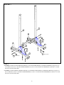
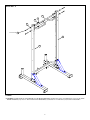
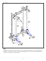
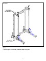
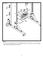
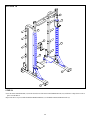
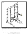
OLYMPIC HEAVY DUTY HALF RACK
(OHDHR)
ASSEMBLY INSTRUCTIONS
Part # 7671201
Rev. A
1
Revision:12/12/03
PARTS LIST
KEY
1
2
3
4
5
6
7
8
9
10
11
12
13
14
KEY
15
16
17
18
19
20
21
22
23
24
25
26
QTY
DESCRIPTION
PART #
1
LEFT UPRIGHT BASE
LEA7664801
1
RIGHT
UPRIGHT
BASE
LEA7665001
1
LEFT UPRIGHT SUPPORT
LEA7665101
2
REAR UPRIGHT
LEA7584901
1
RIGHT
UPRIGHT
SUPPORT
LEA7665501
2
WEIGHT HORN UPRIGHT
LEA7586601
1
LEFT
BAR
CATCH
LEA7622401
1
PULL-UP SUPPORT
LEA7663901
LEA7584401 RIGHT ADJUSTMENT RACK 1
1
LEA7584501 LEFT ADJUSTMENT RACK
10
WEIGHT HORN
LEA7587501
1
LEFT
BAR
SUPPORT
LEA7587901
1
RIGHT BAR SUPPORT
LEA7587801
1
RIGHT BAR CATCH
LEA7605901
PART #
LEA7596501
LEA3239306
LEA3245201
LEA3102502
LEA3237505
LEA3239503
LEA7617301
LEA3102801
LEA3102802
LEA7601701
LEA3239317
LEA3105303
QTY
DESCRIPTION
BOTTOM UPRIGHT SUPPORT 1
4
1/2 X 1-1/2” BOLT
3/8 X 3-3/4” FLAT HEAD BOLT 8
4
1/2” FLAT WASHER
52
1/2” INTTOOTH LOCK WASHER
3/8” INTTOOTH LOCK WASHER 8
48
1/2” PLASTIC DOME WASHER
52
1/2” LOCK NUT
8
3/8” LOCK NUT
2
SWIVEL SPOTTER
48
1/2 X 4-1/4” BOLT
6
9/16” HOLE CAP
Tools Required for Assembly
* 3/4”, 9/16” wrench
* Ratchet with 3/4”, 9/16” socket
* 7/32” Allen Wrench
Bolt Length Ruler
NOTE: BOLT LENGTH IS MEASURED FROM THE UNDERSIDE OF THE HEAD OF THE BOLT.
BOLT LENGTH
0
1
1/2
10
20
1/2
30
40
2
50
3
1/2
60
70
1/2
80
2
90
4
100
5
1/2
110
120
6
1/2
130
140
150
16 1/2 X 1-1/2” BOLT
25 1/2 X 4-1/4” BOLT
17 3/8 X 3-3/4” FLAT HEAD BOLT
19
1/2” INT TOOTH
LOCK WASHER
21
1/2” PLASTIC
DOME WASHER
20
3/8” INT TOOTH
LOCK WASHER
18
1/2”
FLAT WASHER
23
3/8”
LOCK NUT
22
1/2”
LOCK NUT
3
FIGURE 1
4
4
2
22
19
1
21
25 1/2 X 4-1/4”
STEP 1:
• LOOSELY assemble the REAR UPRIGHT (4) to the LEFT UPRIGHT BASE (1) using two 1/2 X 4-1/4” BOLTS (25), two 1/2” PLASITC
DOME WASHERS (21), two 1/2” INT TOOTH LOCK WASHERS (19) and two 1/2” LOCK NUTS (22) as shown in FIGURE 1.
• LOOSELY assemble the REAR UPRIGHT (4) to the RIGHT UPRIGHT BASE (2) using two 1/2 X 4-1/4” BOLTS (25), two 1/2” PLASITC
DOME WASHERS (21), two 1/2” INT TOOTH LOCK WASHERS (19) and two 1/2” LOCK NUTS (22) as shown in FIGURE 1.
4
4
4
Use this set of holes for
assembly without PLATFORM.
22
19
15
21
25 1/2 X 4-1/4”
26
Use this set of holes for
assembly with PLATFORM.
FIGURE 2
STEP 2:
• LOOSELY assemble the BOTTOM UPRIGHT SUPPORT (15) to the REAR UPRIGHTS (4) using four 1/2 X 4-1/4” BOLTS (25), four
1/2” PLASITC DOME WASHERS (21), four 1/2” INT TOOTH LOCK WASHERS (19) and four1/2” LOCK NUTS (22) as shown in
FIGURE 2.
• Insert six 9/16” HOLE CAPS (26) into the holes of the REAR UPRIGHTS (4) as shown in FIGURE 2.
5
FIGURE 3
4
4
22
19
5
2
22
21
3
21
19
1
25 1/2 X 4-1/4”
25 1/2 X 4-1/4”
STEP 3:
• LOOSELY assemble the LEFT UPRIGHT SUPPORT (3) to the LEFT UPRIGHT BASE (1) and REAR UPRIGHT (4) using four 1/2 X
4-1/4” BOLTS (25), four 1/2” PLASITC DOME WASHERS (21), four 1/2” INT TOOTH LOCK WASHERS (19) and four 1/2” LOCK
NUTS (22) as shown in FIGURE 3.
• LOOSELY assemble the RIGHT UPRIGHT SUPPORT (5) to the RIGHT UPRIGHT BASE (2) and REAR UPRIGHT (4) using four 1/2
X 4-1/4” BOLTS (25), four 1/2” PLASITC DOME WASHERS (21), four 1/2” INT TOOTH LOCK WASHERS (19) and four 1/2” LOCK
NUTS (22) as shown in FIGURE 3.
6
FIGURE 4
8
22
19
21
1/2 X 4-1/4” 25
4
4
STEP 4:
• LOOSELY assemble the PULL-UP SUPPORT (8) to the REAR UPRIGHTS (4) using four 1/2 X 4-1/4” BOLTS (25), four 1/2” PLASTIC
DOME WASHERS (21), four 1/2” INT TOOTH LOCK WASHERS (19) and four 1/2” LOCK NUTS (22) as shown in FIGURE 4.
7
FIGURE 5
6
6
22
19
21
1/2 X 4-1/4” 25
4
4
22
19
2
21
25 1/2 X 4-1/4”
1
STEP 5:
• LOOSELY assemble the WEIGHT HORN UPRIGHTS (6) to the LEFT & RIGHT UPRIGHT BASE (1 & 2) and REAR UPRIGHTS (4)
using eight 1/2 X 4-1/4” BOLTS (25), eight 1/2” PLASTIC DOME WASHERS (21), eight 1/2” INT TOOTH LOCK WASHERS (19)
and eight 1/2” LOCK NUTS (22) as shown in FIGURE 5.
8
FIGURE 6
TIGHTEN
BOTH SIDES!
TIGHTEN
BOTH SIDES!
STEP 6:
• Securely tighten all loose frame connections made to this point.
9
FIGURE 7
4
9
4
10
4
3/8 X 3-3/4” 17
1
12
20
3
10
23
4
13
2
DETAIL 7
STEP 7:
• LOOSELY assemble one RIGHT & one LEFT ADJUSTMENT RACK (9 & 10) to the REAR UPRIGHTS (4) as shown, using eight
3/8 X 3-3/4” FLAT HEAD BOLTS (17), eight 3/8” INT TOOTH LOCK WASHERS (20) and eight 3/8” LOCK NUTS (23). See FIGURE 7.
SETTINGADJUSTMENT RACK WIDTH (SEE DETAIL 7)
• Before tightening the ADJUSTMENT RACKS (9 & 10), slide the LEFT and RIGHT BAR SUPPORTS (12 & 13) over the ADJUSTMENT RACK and REAR UPRIGHT. Assemble one BAR SUPPORT close to the top and the other close to the bottom, as shown
in DETAIL 7. (Make sure not to cover any bolt heads.) Proceed to tighten all four bolts in the order shown in DETAIL 7. Repeat
this step on the remaining ADJUSTMENT RACK.
10
FIGURE 8
6
6
21
11
19
22
1/2 X 4-1/4” 25
STEP 8:
• SECURELY assemble the ten WEIGHT HORNS (11) to the WEIGHT HORN UPRIGHTS (6) using twenty 1/2 X 4-1/4” BOLTS (25),
twenty 1/2” INT TOOTH LOCK WASHERS (19), twenty 1/2” PLASTIC DOME WASHERS (21) and twenty 1/2” LOCK NUTS (22) as
shown in FIGURE 8.
11
FIGURE 9
24
22
18
16 1/2 X 1-1/2”
19
15
STEP 9:
• Assemble two SWIVEL SPOTTERS (24) to the BOTTOM UPRIGHT SUPPORT (15) as shown using four 1/2 X 1-1/2” BOLTS (16), four
1/2” INT TOOTH LOCK WASHERS (19), four 1/2” FLAT WASHERS (18) and four 1/2” LOCK NUTS (22). See FIGURE 9. (NOTE:
Tighten connection SECURELY then back nut off 1/2 turn.)
12
FIGURE 10
4
13
4
12
9
10
2
1
STEP 10:
• Insert the LEFT BAR SUPPORT (12) into the desired slots of the LEFT ADJUSTMENT RACK (10), and allow it to drop down to lock in
place. See FIGURE 10.
• Repeat the above step to assemble the RIGHT BAR SUPPORT (13) to the RIGHT ADJUSTMENT RACK (9).
13
FIGURE 11
9
14
10
7
SERIAL NUMBER
STEP 11:
• Insert the LEFT BAR CATCH (7) into the desired slots of the LEFT ADJUSTMENT RACK (10), and allow it to drop down to lock in
place. See FIGURE 11.
• Repeat the above step to assemble the RIGHT BAR CATCH (14) to the RIGHT ADJUSTMENT RACK (9).
Thank you for purchasing the OLYMPIC HEAVY DUTY HALF RACK. If unsure of proper use of
equipment, call your local Hammer Strength distributor .
14
CAUTION-PLEASE READ
There is a risk assumed by individuals who use this type of equipment. To minimize risk, please
follow these rules:
1. Inspect equipment daily. Tighten all loose connections and replace worn parts immediately.
Failure to do so may result in serious injury.
2. Do not allow minors or children to play on or around this equipment.
3. Exercise with care to avoid injury.
4. Consult your physician before beginning any exercise program.
WARRANTY INFORMATION
10 YEARS
5 YEARS
1 YEAR
90 DAYS
Structural Frame
(Not Coatings)
Pillow Blocks, Pulleys,
Weight Plates, and Guide Rods
Belts and Grips
Upholstery and Any Items
Not Specified
Asia Pacific
(+852)2891.6677
United Kingdom
+44(0)1353.666017
CONTACT INFORMATION
United States, Canada,
Latin America
800.634.8637
847.288.3399
Europe, Africa, Middle East
(+31) 180.646666
VISIT US AT:
HAMMERSTRENGTH.COM
PREVENTATIVE MAINTENANCE TIPS
Action
DAILY WEEKLY QUARTERLY BI-ANNUALLY AS NEEDED
CLEAN
Upholstery
X
Guide Rods
X
Hand Grips
X
INSPECT
Visual Overall
X
Cables
X
Hardware
X
Frame
X
Hand Grips
X
LUBRICATE
Guide Rods
X
Clean:
• Upholstery with mild soap and water.
• Guide rods with a cotton cloth.
• Hand grips with mild soap and water.
• Frame damage can be repaired with touch-up paint can be purchased from your Hammer Strength customer service representative.
Inspect:
• Cables for wear or damage and proper tension (should not exceed 3/4” deflection.) Pay close attention at bends and attachment
points.
• Hardware should be checked for looseness. Tighten as required.
• Frames should be inspected for wear or damage.
• Hand Grips should be checked for wear or damage
Lubricate:
• Lube the Guide Rods. Apply the lubricant to a cotton cloth, then run the cotton cloth up and down the guide rods as needed. Do not
spray lubricant directly on the Guide Rods.
15