1
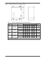
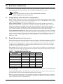
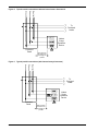
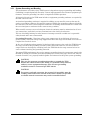
POWER PROTECTION
Interceptor II
Transient Voltage Surge Suppressor
Installation, Operation
& Maintenance Manual
TABLE OF CONTENTS
1.0
INTRODUCTION . . . . . . . . . . . . . . . . . . . . . . . . . . . . . . . . . . . . . . . . . . . . . . . . . . . . . . . 1
2.0
UNPACKING AND INSTALLATION . . . . . . . . . . . . . . . . . . . . . . . . . . . . . . . . . . . . . . . . . . . 2
2.1
Unpacking and Preliminary Inspection . . . . . . . . . . . . . . . . . . . . . . . . . . . . . . . . . . . . . . . 2
2.2
Handling Considerations . . . . . . . . . . . . . . . . . . . . . . . . . . . . . . . . . . . . . . . . . . . . . . . . . . . 2
2.3
Storage . . . . . . . . . . . . . . . . . . . . . . . . . . . . . . . . . . . . . . . . . . . . . . . . . . . . . . . . . . . . . . . . . 2
2.4
Location Considerations. . . . . . . . . . . . . . . . . . . . . . . . . . . . . . . . . . . . . . . . . . . . . . . . . . . . 2
2.4.1
Equipment Performance . . . . . . . . . . . . . . . . . . . . . . . . . . . . . . . . . . . . . . . . . . . . . . . . . . . . 2
2.5
Door Closing Adjustments . . . . . . . . . . . . . . . . . . . . . . . . . . . . . . . . . . . . . . . . . . . . . . . . . . 2
3.0
ELECTRICAL CONNECTIONS . . . . . . . . . . . . . . . . . . . . . . . . . . . . . . . . . . . . . . . . . . . . . . 4
3.1
Voltage Ratings and Power Source Configurations . . . . . . . . . . . . . . . . . . . . . . . . . . . . . . 4
3.2
Parallel Connection (see Figures 2 and 3) . . . . . . . . . . . . . . . . . . . . . . . . . . . . . . . . . . . . 4
3.2.1
System Grounding and Bonding . . . . . . . . . . . . . . . . . . . . . . . . . . . . . . . . . . . . . . . . . . . . . . 7
4.0
OPERATION . . . . . . . . . . . . . . . . . . . . . . . . . . . . . . . . . . . . . . . . . . . . . . . . . . . . . . . . . 8
5.0
TROUBLESHOOTING, SERVICE & MAINTENANCE . . . . . . . . . . . . . . . . . . . . . . . . . . . . . .10
5.1
Troubleshooting . . . . . . . . . . . . . . . . . . . . . . . . . . . . . . . . . . . . . . . . . . . . . . . . . . . . . . . . . 10
5.2
Service . . . . . . . . . . . . . . . . . . . . . . . . . . . . . . . . . . . . . . . . . . . . . . . . . . . . . . . . . . . . . . . . . 10
5.3
Corrective Maintenance . . . . . . . . . . . . . . . . . . . . . . . . . . . . . . . . . . . . . . . . . . . . . . . . . . . 10
5.4
Preventive Maintenance—Inspection and Cleaning . . . . . . . . . . . . . . . . . . . . . . . . . . . . 10
6.0
LIMITED WARRANTY . . . . . . . . . . . . . . . . . . . . . . . . . . . . . . . . . . . . . . . . . . . . . . . . . . 11
i
FIGURES
Figure 1
Figure 2
Figure 3
Figure 4
Typical cabinet data, Form C contact and wiring . . . . . . . . . . . . . . . . . . . . . . . . . . . . . . . . . . . .
Typical parallel connections (without internal rotary disconnect). . . . . . . . . . . . . . . . . . . . . . .
Typical parallel connections (with internal rotary disconnect) . . . . . . . . . . . . . . . . . . . . . . . . .
Operation controls and indicators . . . . . . . . . . . . . . . . . . . . . . . . . . . . . . . . . . . . . . . . . . . . . . . .
3
6
6
8
TABLES
Table 1
Table 2
Table 3
Table 4
ii
Units with or without internal service disconnect switch . . . . . . . . . . . . . . . . . . . . . . . . . . . . .
Suggested wire and breaker size . . . . . . . . . . . . . . . . . . . . . . . . . . . . . . . . . . . . . . . . . . . . . . . . .
Voltage ratings and power source configurations . . . . . . . . . . . . . . . . . . . . . . . . . . . . . . . . . . . .
Monitoring features . . . . . . . . . . . . . . . . . . . . . . . . . . . . . . . . . . . . . . . . . . . . . . . . . . . . . . . . . . .
3
4
5
8
1.0
INTRODUCTION
The Liebert Interceptor II Series Transient Voltage Surge Suppressor (TVSS) is a high-quality,
high energy surge current diversion system designed to protect sensitive equipment from damaging transient voltage surges. Proper installation is required for maximum system performance.
The installer should perform the following steps to ensure a high-quality installation. The entire
installation manual should be read before starting installation. These instructions do not replace
national or local electrical codes. Check applicable electrical codes to ensure compliance. Installation of the Liebert TVSS system should be performed only by qualified personnel.
Introduction
1
2.0
UNPACKING AND INSTALLATION
2.1
Unpacking and Preliminary Inspection
1. Inspect the shipping crate(s) for damage or signs of mishandling before unpacking the unit.
2. Remove any securing bands and cardboard packing and inspect the unit for any obvious
shipping damages.
3. If any damage as a result of shipping is observed, immediately file a claim with the shipping
agency and forward a copy to your local Liebert sales representative.
2.2
Handling Considerations
Larger units are bolted to a shipping pallet to facilitate handling by forklift or pallet jack. Check
the size and weight. Refer to the cabinet data furnished with the unit. Typical size and weights
are referred to in Table 1.
2.3
Storage
The unit should be stored in a clean, dry environment. Storage temperature range is -55ºC to
+85ºC (-67ºF to +185ºF). Care should be taken to avoid condensation. All packing and shipping
materials should be left intact until the unit is ready for final installation. If the unit has been
stored for an extended period of time, the unit should be cleaned and carefully inspected before
placing into service.
2.4
Location Considerations
Environment—The unit is designed for operation indoors in ambient temperatures of -40°C to
+60ºC (-40ºF to +140ºF) with a relative humidity of 0% to 95% (non-condensing).
The unit is provided in an industrial use enclosure that is dust-tight and drip-tight. The unit
should not be installed in areas with excessive dust, corrosive vapors, flammable materials or
explosive atmospheres.
Audible Noise—The audible noise of the unit is less than 40 dBA at five feet, which allows its
placement in almost any room.
Service Clearances—Service clearance is needed only at the front of the unit. Thirty-six inches
(36 in or 914 mm) minimum is recommended.
2.4.1
Equipment Performance
For maximum system performance, the unit must be located as close to the protected circuit as
practical to minimize interconnecting wiring length.
For optimum transient surge protection, coordinated surge suppression should be applied at the
service entrance and all other electrical connections to the building (telephone, CATV, etc.), at
known surge generating loads within the building (large motors, arc welders, switched capacitors,
etc.), as well as at sensitive electronic loads (such as computers, electronic appliances, solid state
motor drives, etc.). For interconnected electronic loads (such as by way of data cabling), transient
surge suppression should also be applied to the interconnecting wiring (data cables).
Mounting—Unit is intended to be wall-mounted. Refer to Figure 1 or unit submittal drawings
for typical mounting dimensions and weight.
2.5
Door Closing Adjustments
If the surface on which the enclosure is mounted is not flat, the door may not open and close properly. Also, if heavy equipment is mounted on a large door, the door may sag slightly. If the top of
the door strikes the lip that extends around the body opening, place metal shims behind the
mounting foot that is located at the bottom of the enclosure and closest to the door hinge. Place
the shims between the mounting foot and the wall or mounting surface. Be sure all mounting
screws are tightened securely
2
Unpacking and Installation
Figure 1
Typical cabinet data, Form C contact and wiring
Table 1
Units with or without internal service disconnect switch
Dimensions (Inches)
**Model
Series
Application
SI016
SI025
All voltage
configurations*
SI032
SI040
SI050
All voltage
configurations*
SI060
SI075
All voltage
configurations*
SI100
All voltage
configurations*
Connection
A
B
C
D
E
F
Weight
(lbs.)
Wire Lugs
16
12
9
16.75
10
0.31
35
Disconnect
(optional)
16
16
9
16.75
14
0.31
45
Wire Lugs
16
16
9
16.75
14
0.31
45
Disconnect
(optional)
20
16
9
21.25
10
0.44
55
Wire Lugs
20
16
9
21.25
10
0.44
55
Disconnect
(optional)
20
20
9
21.25
14
0.44
85
Wire Lugs
20
20
9
21.25
14
0.44
85
Disconnect
(optional)
20
24
9
21.25
18
0.44
95
*Single Phase L – N, Single Phase L – L, Split Phase, Three Phase Wye, Three Phase Delta, Three Phase Delta Hi-Leg
** First five digits of model number
Unpacking and Installation
3
3.0
ELECTRICAL CONNECTIONS
All electrical connections should be installed only by a qualified (licensed) electrician. All wiring
must comply with the National Electrical Code (NEC) and applicable local codes.
CAUTION
Verify that all power circuits are de-energized and locked out
before making electrical connections.
!
3.1
Voltage Ratings and Power Source Configurations
Before making connections to the unit, verify that the unit model number and nameplate voltage
rating are appropriate for connection to the intended power source. See Table 3 for voltage rating
applications with typical power source configurations.
Surge Voltage Ratings—To obtain the suppression voltage ratings (SVRs), as obtained by
Underwriters Laboratory, Incorporated, in accordance with the Standard for Safety, Transient
Voltage Surge Suppressors (TVSS), Standard 1449, Second Edition, dated August 15, 1996,
marked on this product, #2 AWG wire must be utilized to connect the unit to your facilities’ power
grid. Connections made with conductors other that #2 AWG may result in different SVRs.
Circuit Ampacity Limitations—Representative samples of this product have been investigated
by Underwriters Laboratories, Incorporated to withstand, without exposing live circuits or components at system voltages and fault currents of up to 200,000 AIC, as described in the Standard for
Safety, Transient Voltage Surge Suppressor (TVSS), Standard 1449, Second Edition, dated
August 15, 1996.
3.2
Parallel Connection (see Figures 2 and 3)
With parallel connection, the length of the wiring to the Transient Voltage Surge Suppressor (TVSS)
unit must be minimized for best performance. Wires should be as short and straight as possible.
To reduce the wiring impedance to surge currents, the phase, neutral (if required), and ground
conductors are recommended to be twisted together and routed in the same raceway (conduit).
Avoid any sharp bends in the conductors.
Wire Sizing—With parallel connection, the size of the wiring to the TVSS unit is independent of
the protected circuit’s ampacity. Suggested wire size based on the unit’s transient surge current
capabilities are show in the table below.
Table 2
Suggested wire and breaker size
Model Series
Outline Drawing
Wire Size
Breaker Size
SI016 –SI025 Wire Lugs
82010
8-1/0
40A
SI016 –SI025 Disconnect
82011
8-1/0
40A
S0320 –SI050 Wire Lugs
82012
4-1/0
80A
S0320 –SI050 Disconnect
82013
4-1/0
80A
SI060 –SI075 Wire Lugs
82014
4-1/0
80A
SI060 –SI075 Disconnect
82015
4-1/0
80A
SI100 Wire Lugs
82016
4-1/0
80A
SI100 Disconnect
82017
4-1/0
80A
NEC Articles 280-21 and 22 require surge arrestor connecting conductors to be at least #14 copper
or #12 aluminum.
Overcurrent Protection—The TVSS unit conducts practically no current under normal operation and conducts only very short duration transient surge currents.
External overcurrent protection is not specifically required by NEC Article 280 nor is it desired
since it impedes the performance of the transient voltage surge suppressor. If fusing is required,
please consult factory for recommendations.
4
Electrical Connections
Disconnect Switch—TVSS units must be connected to the load side of the main service disconnect, or load side of a protected circuit’s disconnecting means.
Interceptor II “SI” Models with an “R” designator in the part number, are equipped with an internal disconnect switch, that can be used to de-energize the unit’s transient surge suppressing components for servicing.
Table 3
Voltage ratings and power source configurations
Source Configurations
L
L
N
Nominal Operating Voltage
Model Voltage
L-N
L-L
L-G
Code
120
N/A
120
120N
230
N/A
230
230N
277
N/A
277
277N
N/A
208
208
208L
N/A
240
240
240L
N/A
480
480
480L
120
208-240
120
120S
230
400-460
230
230S
277
480-554
277
277S
N/A
208
208
208D
N/A
240
240
240D
N/A
480
480
480D
120
240
120
240H
240
480
240
480H
120
208
120
120Y
230
400
230
230Y
277
480
277
277Y
N
G
G
Single Phase L-N 2W+G
Single Phase L-L 2W+G
Split Phase 3W+G
Three Phase Delta 3W+G
Three Phase Delta Hi-Leg 4 W+G
Three Phase Wye 4W+G
For other voltages or source configurations, consult factory.
Electrical Connections
5
Figure 2
Typical parallel connections (without internal rotary disconnect)
Neutral
Phases
Ground
To
Protected
Loads
Liebert
Surge
Protective
Device
Protected
Panel
Figure 3
Wire should be
less than 5 feet
and straight as
possible
Typical parallel connections (with internal rotary disconnect)
Neutral
Phases
Ground
To
Protected
Loads
Liebert
Surge
Protective
Device
Protected
Panel
6
Electrical Connections
Wire should be
less than 5 feet
and straight as
possible
3.2.1
System Grounding and Bonding
The performance and safety of any TVSS system is dependent on proper grounding and bonding.
Grounding is required primarily for safety. Correct implementation also enhances equipment performance. Incorrect grounding can reduce or impede the TVSS's operation.
All electrical circuits to the TVSS must include an equipment grounding conductor as required by
the NEC and local codes.
An insulated grounding conductor is required in addition to any metallic raceway that may be
used as a grounding conductor. For parallel-connected TVSSs, the grounding conductor should be
the same wire size as the associated power conductors. Grounding conductors must be routed with
the associated power conductors in the same raceway (conduit).
When metallic raceways are used, adequate electrical continuity must be maintained at all raceway connections, particularly raceway terminations to the electrical enclosures.
The use of isolating bushings or other means to interrupt a metallic conduit run is a potential
safety hazard and is not recommended.
Grounding Electrode—Transient voltage surge suppressors do not discharge all surges to
ground (earth). Transient voltage surge suppressors divert the surge current back to its source to
complete the electrical circuit.
In the case of lightning whose potential is developed with respect to the earth, the TVSS diverts
the surge current to the grounding electrode (earth connection). However, for most transient
surges which are developed by switching loads, the TVSS diverts the surge current back to its
source without involving the grounding electrode.
For proper TVSS performance, the service entrance grounding electrode system must comply with
the NEC by having all available electrodes (building steel, metal water pipe, driven rods, concrete
encased electrodes, etc.) properly bonded together and connected to the power system grounding.
!
!
CAUTION
The use of a separate grounding electrode to ground the TVSS
defeats the effectiveness of the TVSS, is a potential safety hazard,
and may cause equipment damage. The arrestor grounding
conductor must be connected per NEC 280-21.
CAUTION
For proper and safe operation, the neutral, (if provided), must be
reliably connected to the neutral of the source. Failure to provide
a reliable neutral connection may result in module failure!
Electrical Connections
7
4.0
OPERATION
Table 4
Monitoring features
Monitoring Features
“S” Package
“C” Package
“D” Package
LED Status Indicators
✔
✔
✔
Built-In Component Integrity Test
(BICIT)
✔
✔
✔
Sonic Alarm
✔
✔
✔
✔
✔
✔
✔
✔
✔
Optional
Optional
Optional
Form C Dry Contacts
Surge Counter
Swell Counter
Remote Monitor Panel
Figure 4
Operation controls and indicators
Status LED Indicators—Green and red LEDs for each protected phase provide a visual status
summary of all surge modules within device.
Full Protection LEDs—Green LEDs are illuminated only when all surge components are at
100% percent efficiency.
Reduced Protection—Red LED illuminated only when protection has been reduced by off-line
surge components such as open fuse links.
Built-In Component Integrity Test (BICIT)—While the monitoring circuitry provides visual
status during operation, the built-in test circuitry will verify that every fuse link and associated
MOV is operational. The built-in-test may be operated easily by simply pressing one push button
during normal operation. The BICIT cycles through each phase bank including neutral-ground
sending out a test request signal to all modules. If all fuse links are in intact the red reduced-protection LED for the particular bank in test will illuminate for a two to four seconds. Should this
light stay lit for more than 5 seconds, one module in that bank has at least one open fuse link.
While testing, the Test LED will illuminate. Also, during the built-in test sequence, the alarm
should sound for each bank. Pressing the alarm disable switch before or during the test will
silence the alarm.
Sonic Alarm—If one or more of the surge modules require replacement, an audible alarm is activated to draw attention to the fact that repair service is required to restore the system to normal
operation. An audible alarm disable button is provided to silence the alarm. The system will automatically reset itself after repair.
8
Operation
Form C Dry Contacts—Dual summary alarm Form C (1 N.O. and 1 N.C.) relay contacts are
provided for remote indication of each failed surge current modules. The summary alarm contacts
terminals are located on the PC board inside the unit. Contacts are rated for 5 amps at 240 VAC
with a power factor of 1.0. The states of the Form C Dry Contacts are determined with power
applied. Connection to the Form C Dry Contacts are provided by #18 AWG wires attached to the
status module. The yellow wire is for connection to the NO contact. The blue wire is for connection
to the NC contact. The orange wire is for connection to the common point of the Form C Dry Contacts.
Surge Counter—The Surge Counter monitors line to ground transient voltages. This circuit
totalizes all surges that deviate from the line sine wave envelope by more than 125 volts. The
counter is AC coupled and rejects transient voltages longer than 100µs.
Swell Counter—The Swell Counter monitors all line to line and line to neutral voltages. It is factory set to record whenever the peak voltage on any normal mode exceeds the MCOV of the TVSS
for more than 100µs. This allows the counter to record temporary line over voltages that many
result from utility switching, line regulation problems, etc.
Remote Monitor Panel—A remote monitor panel is available to provide unit status and alarm
information at a location up to 500 feet away from the Liebert TVSS System. (See Table 4.) Operation of the Remote Monitor Panel is similar to the unit system monitor panel. The “Enable” position of the switch is the normal position, which allows audible alarm operation. The “Disable”
switch position silences the audible alarm. The “Test” position tests the audible alarm and indicator lights. The remote monitor panel requires an external source of power. Standard units are furnished with a six-foot line-cord with a 5-15P NEMA plug.
Operation
9
5.0
TROUBLESHOOTING, SERVICE & MAINTENANCE
5.1
Troubleshooting
If status failure indication occurs or Form C relay has changed states, a qualified electrician
should first determine if the systems voltage and proper phasing exists.
If the Interceptor II TVSS remains in an alarm condition once the technician is satisfied that the
electrical system and its connections are normal, the unit should be repaired. At this point consult
the factory, having available the following information:
• Unit identification number—the model and serial numbers detailed on the data label on the
upper left (hinge) side of the enclosure
• Nature of problem—including status of all status indicators and alarms.
5.2
Service
!
WARNING
ONLY QUALIFIED PERSONNEL SHOULD PERFORM
MAINTENANCE ON THE SYSTEM.
HAZARDOUS VOLTAGES ARE PRESENT INSIDE THE UNIT
DURING NORMAL OPERATIONS.
ELECTRICAL SAFETY PRE-CAUTIONS MUST BE FOLLOWED
WHEN SERVICING THIS UNIT.
TO PREVENT RISK OF ELECTRICAL SHOCK, TURN OFF AND
LOCK OUT ALL POWER SOURCES TO THE UNIT BEFORE
SERVICING UNIT.
FOR SERVICING ASSISTANCE, CONTACT YOUR LOCAL
LIEBERT SALES REPRESENTATIVE OR LIEBERT AT
800-288-6169 OR 607-724-2484.
5.3
Corrective Maintenance
The Liebert Interceptor II TVSS is designed for years of trouble-free operation. However, even the
most reliable equipment may fail under abnormal conditions.
Diagnostic indicators are provided to indicate when the unit needs replacement (see 4.0 - Operation for details). To ensure continuity of surge protection, failed units should be replaced at the
earliest convenient service opportunity. On systems rated greater than 100 kAmp surge capacity
and larger, parallel modules provide redundant transient surge protection such that any single
module failure does not completely eliminate the TVSS protection.
When replacing surge modules, other components should be inspected for damage and replaced if
necessary. Standard electrical troubleshooting procedures should be used to isolate problems
other than failed surge current diverter modules.
When replacing components, for continued proper operation and safety, replace only with identically rated components. Please contact factory for information on replacement parts.
5.4
Preventive Maintenance—Inspection and Cleaning
Periodic system inspections, cleaning, and connection checks are recommended to ensure reliable
system performance and continued surge transient protection.
It is difficult to establish a schedule for preventive maintenance since conditions vary from site to
site. Inspections for failed surge current diverter modules using available diagnostics should be
done routinely (weekly or monthly).
10
Troubleshooting, Service & Maintenance
6.0
LIMITED WARRANTY
This Warranty is given ONLY to purchasers who buy for commercial or industrial use in the ordinary course of each purchaser's business.
General:
Liebert’s products are in our opinion the finest available. We take pride in our products and are
pleased that you have chosen them. Under certain circumstances, we offer with our products the
following Five-Year Warranty Against Defects in Material and Workmanship. Please read your
Warranty carefully. This Warranty sets forth our responsibilities in the unlikely event of defect
and tells you how to obtain performance under this Warranty.
Five Year Limited Warranty Against Defects In Material And Workmanship
Liebert products covered: Interceptor II and Interceptor Hybrid Advantage (SAD) Series TVSS.
Terms of Warranty:
As provided herein, the Liebert product is warranted to be free of defects in material and workmanship for a period of five (5) years from the date of delivery of the product to User. The delivery
date will be determined only from the Liebert bill of lading. If any of the Liebert products fail to
conform to the warranty within the warranty period, Liebert, at its option, will furnish new or factory remanufactured parts for repair or replacement of that part.
Warranty Extends to First Purchaser for Use, Non-transferable:
This Warranty is extended to the first person, firm, association or corporation for whom the Liebert product specified herein is originally installed for use in the United States (the "User"). This
Warranty is not transferable or assignable without the prior written permission of Liebert.
Assignment of Warranties:
Liebert assigns to User any warranties which are made by manufacturers and suppliers of components of the Liebert product and which are assignable, but Liebert makes NO REPRESENTATIONS as to the effectiveness or extent of such warranties, assumes NO RESPONSIBILITY for
any matters which may be warranted by such manufacturers or suppliers and extends no coverage under this warranty to such components.
Descriptions:
Liebert warrants for the period and on the terms of the Warranty set forth herein that the Liebert
product will conform to the descriptions contained in Liebert' final invoices, orders and Liebert'
product brochures. Liebert does not control the installation and use of any Liebert product.
Accordingly, it is understood that the Descriptions are NOT WARRANTIES OF PERFORMANCE
and NOT WARRANTIES OF FITNESS FOR A PARTICULAR PURPOSE.
Obtaining Performance Under This Warranty:
Within a reasonable time, but in no case to exceed thirty (30) days, after User's discovery of a
defect, User shall contact Liebert and request a return authorization number. User shall ship the
product, with proof of purchase, to Liebert freight prepaid. Liebert products shipped to Liebert
without a return authorization number will be refused and returned freight collect to User at
User's expense. Liebert products shipped by User to Liebert which have incurred freight damage
due to User's improper packaging of the product will not be covered by this Warranty and any
repairs or replacement parts, components or products needed will be invoiced in the full current
price amount and returned freight collect to User.
Subject to the limitations specified herein, Liebert will repair or replace, at its option, without
charge for Liebert labor or materials, subsequent to its inspection and F.O.B. Liebert' facility, the
Liebert product shipped to Liebert with a return authorization number and warranted hereunder
which does not conform to the Warranty. Replacement parts, components or products shipped to
User prior to Liebert' receipt and inspection of the product claimed to be defective, shall be
invoiced in the full current price amount and shipped freight collect F.O.B. Liebert' facility. Warranty coverage will be extended only after Liebert' receipt of the claimed defective product within
thirty (30) days of shipment of any replacement parts, components or products, if applicable, Liebert' inspection discloses the claimed defect and the returned product shows no signs of treatment
or use which would void the coverage of this Warranty.
Limited Warranty
11
Items Not Covered By Warranty:
THIS WARRANTY DOES NOT COVER DAMAGE OR DEFECT CAUSED BY misuse, improper
application, wrong or inadequate electrical current or connection, inadequate water or drain services, negligence, inappropriate on site operating conditions, corrosive atmosphere, repair by nonLiebert designated personnel, accident in transit, tampering, alterations, a change in location or
operating use, exposure to the elements, Acts of God, theft or installation contrary to Liebert' recommendations or specifications, or in any event if the Liebert serial number has been altered,
defaced or removed.
THIS WARRANTY DOES NOT COVER shipping costs, installation costs, circuit breaker resetting or maintenance or service items and further, except as provided herein, does NOT include
labor costs or transportation charges arising from the replacement of the Liebert product or any
part thereof or charges to remove same from any premises of the User.
THIS WARRANTY DOES NOT COVER DAMAGE OR DEFECT CAUSED BY use of the Liebert
product in combination with any electrical or electronic components, circuits, systems, assemblies, or other materials not furnished by Liebert. Liebert does NOT warrant the suitability for
use or the results of the Liebert product in combination with the products of others.
REPAIR OR REPLACEMENT OF A DEFECTIVE PRODUCT OR PART THEREOF DOES NOT
EXTEND THE ORIGINAL WARRANTY PERIOD.
Limitations:
THIS WARRANTY IS IN LIEU OF AND EXCLUDES ALL OTHER WARRANTIES, EXPRESS
OR IMPLIED, INCLUDING MERCHANTABILITY AND FITNESS FOR A PARTICULAR PURPOSE.
USER'S SOLE AND EXCLUSIVE REMEDY IS REPAIR OR REPLACEMENT OF THE LIEBERT PRODUCT AS SET FORTH HEREIN.
IF USER'S REMEDY IS DEEMED TO FAIL OF ITS ESSENTIAL PURPOSE BY A COURT OF
COMPETENT JURISDICTION, LIEBERT' RESPONSIBILITY FOR PROPERTY LOSS OR
DAMAGE SHALL NOT EXCEED ONE TIMES THE NET PRODUCT PURCHASE PRICE.
IN NO EVENT SHALL LIEBERT ASSUME ANY LIABILITY FOR INDIRECT, SPECIAL, INCIDENTAL, OR ECONOMIC CONSEQUENTIAL DAMAGES OF ANY KIND WHATSOEVER,
INCLUDING WITHOUT LIMITATION, LOST PROFITS, BUSINESS INTERRUPTION OR
LOSS OF DATA, WHETHER ANY CLAIM IS BASED UPON THEORIES OF CONTRACT, NEGLIGENCE, STRICT LIABILITY, TORT OR OTHERWISE.
Miscellaneous:
NO SALESPERSON, EMPLOYEE OR AGENT OF LIEBERT IS AUTHORIZED TO ADD TO OR
VARY THE TERMS OF THIS WARRANTY. Warranty terms may be modified, if at all, only in a
writing signed by a Liebert' officer.
This Warranty is effective as of the date of Liebert receipt of payment and supersedes all previous
warranties. Liebert reserves the right to supplement or change the terms of this Warranty in any
subsequent warranty offering to User or others.
In the event that any provision of this Warranty should be or becomes invalid and/or unenforceable during the warranty period, the remaining terms and provisions shall continue in full force
and effect.
This Warranty is given in and is intended to be construed under the laws of the State of Ohio.
This Warranty represents the entire agreement between Liebert and User with respect to the
subject matter herein and supersedes all prior or contemporaneous oral or written communications, representations, understandings or agreements relating to this subject.
12
Limited Warranty
Interceptor
Transient Voltage Surge Suppressor
The Company Behind the Products
With more than 1,000,000 installations around the globe, Liebert is the world leader in computer
protection systems. Since its founding in 1965, Liebert has developed a complete range of support
and protection systems for sensitive electronics:
• Environmental systems: close-control air conditioning from 1.5 to 60 tons
• Power conditioning and UPS with power ranges from 250 VA to more than 1000 kVA
• Integrated systems that provide both environmental and power protection in a single, flexible
package
• Monitoring and control — on-site or remote — from systems of any size or location
• Service and support, through more than 100 service centers around the world, and a 24-hour
Customer Response Center
Liebert Corporation
Liebert Europe
1050 Dearborn Drive
Via Leonardo Da Vinci 8
P.O. Box 29186
Columbus, OH 43229
800.877.9222 Phone
614.841.6022 Fax
Zona Industriale Tognana
35028 Piove Di Sacco
Italy
39-049-9719-111 Phone
39-049-5841-257 Fax
Liebert Asia
Liebert Web Site
23/F Allied Kajima Bldg.
http://www.liebert.com
138 Gloucester Road
Wanchai
Hong Kong
852.2.572.2201 Phone
852.2.831.0114 Fax
While every precaution has been taken to ensure the accuracy and completeness of this literature,
Liebert Corporation assumes no responsibility, and disclaims all liability for damages resulting
from use of this information or for any errors or omissions.
© 2001 Liebert Corporation. All rights reserved throughout the world. Specifications subject to
change without notice.
® Liebert and the Liebert logo are registered trademarks of Liebert Corporation. All names
referred to are trademarks or registered trademarks of their respective owners.
Printed in U.S.A.
SL-22010
Revised: April 2001