1
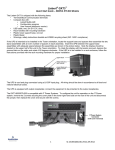
AC Power
For Business-Critical Continuity™
Liebert GXT2-6000RTL630™
User Manual - 208 / 240 VAC
TABLE OF CONTENTS
IMPORTANT SAFETY INSTRUCTIONS . . . . . . . . . . . . . . . . . . . . . . . . . . . . . . . . . . . . . . . . . .1
GLOSSARY OF SYMBOLS . . . . . . . . . . . . . . . . . . . . . . . . . . . . . . . . . . . . . . . . . . . . . . . . . . . . . . .3
1.0
INTRODUCTION . . . . . . . . . . . . . . . . . . . . . . . . . . . . . . . . . . . . . . . . . . . . . . . . . . . . . . . . . .4
2.0
SYSTEM DESCRIPTION . . . . . . . . . . . . . . . . . . . . . . . . . . . . . . . . . . . . . . . . . . . . . . . . . . . .5
2.1
Transient Voltage Surge Suppression (TVSS) and EMI/RFI Filters. . . . . . . . . . . . . . . . . . . . 5
2.2
Rectifier/Power Factor Correction (PFC) Circuit . . . . . . . . . . . . . . . . . . . . . . . . . . . . . . . . . . . 5
2.3
Inverter . . . . . . . . . . . . . . . . . . . . . . . . . . . . . . . . . . . . . . . . . . . . . . . . . . . . . . . . . . . . . . . . . . . . 5
2.4
Battery Charger . . . . . . . . . . . . . . . . . . . . . . . . . . . . . . . . . . . . . . . . . . . . . . . . . . . . . . . . . . . . . 5
2.5
DC-to-DC Converter . . . . . . . . . . . . . . . . . . . . . . . . . . . . . . . . . . . . . . . . . . . . . . . . . . . . . . . . . . 6
2.6
Battery . . . . . . . . . . . . . . . . . . . . . . . . . . . . . . . . . . . . . . . . . . . . . . . . . . . . . . . . . . . . . . . . . . . . 6
2.7
Dynamic Bypass . . . . . . . . . . . . . . . . . . . . . . . . . . . . . . . . . . . . . . . . . . . . . . . . . . . . . . . . . . . . . 6
3.0
MAJOR COMPONENTS . . . . . . . . . . . . . . . . . . . . . . . . . . . . . . . . . . . . . . . . . . . . . . . . . . . .7
3.1
Main Frame and Electronics . . . . . . . . . . . . . . . . . . . . . . . . . . . . . . . . . . . . . . . . . . . . . . . . . . . 7
3.2
Internal Battery Packs. . . . . . . . . . . . . . . . . . . . . . . . . . . . . . . . . . . . . . . . . . . . . . . . . . . . . . . . 8
3.3
Removable Power Distribution Box. . . . . . . . . . . . . . . . . . . . . . . . . . . . . . . . . . . . . . . . . . . . . . 9
4.0
WHAT’S INCLUDED . . . . . . . . . . . . . . . . . . . . . . . . . . . . . . . . . . . . . . . . . . . . . . . . . . . . . . 10
5.0
INSTALLATION AND CONFIGURATION . . . . . . . . . . . . . . . . . . . . . . . . . . . . . . . . . . . . . . . . . 11
5.1
Install the Main Cabinet . . . . . . . . . . . . . . . . . . . . . . . . . . . . . . . . . . . . . . . . . . . . . . . . . . . . . 11
5.1.1
5.1.2
5.1.3
Tower UPS Installation . . . . . . . . . . . . . . . . . . . . . . . . . . . . . . . . . . . . . . . . . . . . . . . . . . . . . . . 11
Rack-Mount UPS Installation . . . . . . . . . . . . . . . . . . . . . . . . . . . . . . . . . . . . . . . . . . . . . . . . . . 12
Installing the Adjustable Rack-Mount Kit—Sold Separately . . . . . . . . . . . . . . . . . . . . . . . . . 12
5.2
Install the Internal Batteries . . . . . . . . . . . . . . . . . . . . . . . . . . . . . . . . . . . . . . . . . . . . . . . . . 14
5.3
Connect the Internal Batteries Using the External Connector . . . . . . . . . . . . . . . . . . . . . . . 15
5.3.1
5.4
Storage . . . . . . . . . . . . . . . . . . . . . . . . . . . . . . . . . . . . . . . . . . . . . . . . . . . . . . . . . . . . . . . . . . . . 15
Connect Input/Output Power. . . . . . . . . . . . . . . . . . . . . . . . . . . . . . . . . . . . . . . . . . . . . . . . . . 15
5.4.1
5.4.2
Attach Power Distribution Box . . . . . . . . . . . . . . . . . . . . . . . . . . . . . . . . . . . . . . . . . . . . . . . . . 16
Distribution Box Electrical Connections . . . . . . . . . . . . . . . . . . . . . . . . . . . . . . . . . . . . . . . . . . 17
5.5
External Battery Cabinet Installation . . . . . . . . . . . . . . . . . . . . . . . . . . . . . . . . . . . . . . . . . . 18
6.0
INITIAL START-UP AND ELECTRICAL CHECKS . . . . . . . . . . . . . . . . . . . . . . . . . . . . . . . . . . 19
7.0
CONFIGURATION PROGRAM . . . . . . . . . . . . . . . . . . . . . . . . . . . . . . . . . . . . . . . . . . . . . . . 20
7.1
GXT2-6000RTL630 Configuration Program Features . . . . . . . . . . . . . . . . . . . . . . . . . . . . . . 20
7.1.1
What You Will Need . . . . . . . . . . . . . . . . . . . . . . . . . . . . . . . . . . . . . . . . . . . . . . . . . . . . . . . . . . 20
8.0
CONTROLS AND INDICATORS. . . . . . . . . . . . . . . . . . . . . . . . . . . . . . . . . . . . . . . . . . . . . . . 21
8.1
ON/Alarm Silence/Manual Battery Test Button . . . . . . . . . . . . . . . . . . . . . . . . . . . . . . . . . . 21
8.2
Standby/Manual Bypass Button . . . . . . . . . . . . . . . . . . . . . . . . . . . . . . . . . . . . . . . . . . . . . . . 21
8.3
Load Level Indicators (4 Green, 1 Amber) . . . . . . . . . . . . . . . . . . . . . . . . . . . . . . . . . . . . . . . 22
8.4
Battery Level Indicators (5 Green) . . . . . . . . . . . . . . . . . . . . . . . . . . . . . . . . . . . . . . . . . . . . . 22
8.5
Fault Indicator LED (Red) . . . . . . . . . . . . . . . . . . . . . . . . . . . . . . . . . . . . . . . . . . . . . . . . . . . . 22
i
8.6
Bypass Indicator LED (Amber) . . . . . . . . . . . . . . . . . . . . . . . . . . . . . . . . . . . . . . . . . . . . . . . . 22
8.7
UPS ON Indicator LED (Green) . . . . . . . . . . . . . . . . . . . . . . . . . . . . . . . . . . . . . . . . . . . . . . . 22
8.8
Battery Indicator LED (Amber). . . . . . . . . . . . . . . . . . . . . . . . . . . . . . . . . . . . . . . . . . . . . . . . 22
8.9
AC Input Indicator LED (Green) . . . . . . . . . . . . . . . . . . . . . . . . . . . . . . . . . . . . . . . . . . . . . . . 22
9.0
OPERATING INSTRUCTIONS . . . . . . . . . . . . . . . . . . . . . . . . . . . . . . . . . . . . . . . . . . . . . . . . 23
9.1
Normal Mode Operation. . . . . . . . . . . . . . . . . . . . . . . . . . . . . . . . . . . . . . . . . . . . . . . . . . . . . . 23
9.2
Battery Mode Operation . . . . . . . . . . . . . . . . . . . . . . . . . . . . . . . . . . . . . . . . . . . . . . . . . . . . . 23
9.3
Bypass Mode Operation . . . . . . . . . . . . . . . . . . . . . . . . . . . . . . . . . . . . . . . . . . . . . . . . . . . . . . 23
9.4
Battery Recharge Mode . . . . . . . . . . . . . . . . . . . . . . . . . . . . . . . . . . . . . . . . . . . . . . . . . . . . . . 23
10.0
COMMUNICATIONS . . . . . . . . . . . . . . . . . . . . . . . . . . . . . . . . . . . . . . . . . . . . . . . . . . . . . . 24
10.1
Communications Interface Port. . . . . . . . . . . . . . . . . . . . . . . . . . . . . . . . . . . . . . . . . . . . . . . . 24
10.2
Pin 4 - Remote Shutdown on Battery . . . . . . . . . . . . . . . . . . . . . . . . . . . . . . . . . . . . . . . . . . . 24
10.3
UPS Intelligent Communications . . . . . . . . . . . . . . . . . . . . . . . . . . . . . . . . . . . . . . . . . . . . . . 25
10.4
Remote Emergency Power Off . . . . . . . . . . . . . . . . . . . . . . . . . . . . . . . . . . . . . . . . . . . . . . . . . 26
11.0
MAINTENANCE . . . . . . . . . . . . . . . . . . . . . . . . . . . . . . . . . . . . . . . . . . . . . . . . . . . . . . . . . 27
11.1
Internal Battery . . . . . . . . . . . . . . . . . . . . . . . . . . . . . . . . . . . . . . . . . . . . . . . . . . . . . . . . . . . . 27
11.1.1 Internal Battery Replacement . . . . . . . . . . . . . . . . . . . . . . . . . . . . . . . . . . . . . . . . . . . . . . . . . 28
11.2
AC Power Connections . . . . . . . . . . . . . . . . . . . . . . . . . . . . . . . . . . . . . . . . . . . . . . . . . . . . . . . 29
11.2.1 Disconnect . . . . . . . . . . . . . . . . . . . . . . . . . . . . . . . . . . . . . . . . . . . . . . . . . . . . . . . . . . . . . . . . . . 29
11.2.2 Reconnect . . . . . . . . . . . . . . . . . . . . . . . . . . . . . . . . . . . . . . . . . . . . . . . . . . . . . . . . . . . . . . . . . . 30
12.0
TROUBLESHOOTING . . . . . . . . . . . . . . . . . . . . . . . . . . . . . . . . . . . . . . . . . . . . . . . . . . . . . 31
12.0.1 Auto-Learning Battery Run Times . . . . . . . . . . . . . . . . . . . . . . . . . . . . . . . . . . . . . . . . . . . . . . 35
13.0
SPECIFICATIONS . . . . . . . . . . . . . . . . . . . . . . . . . . . . . . . . . . . . . . . . . . . . . . . . . . . . . . . .36
FIGURES
Figure 1
Figure 2
Figure 3
Figure 4
Figure 5
Figure 6
Figure 7
Figure 8
GXT2-6000RTL630, front view . . . . . . . . . . . . . . . . . . . . . . . . . . . . . . . . . . . . . . . . . . . . . . . . . . . . . 7
GXT2-6000RTL630, rear view . . . . . . . . . . . . . . . . . . . . . . . . . . . . . . . . . . . . . . . . . . . . . . . . . . . . . . 8
Internal battery pack with connector . . . . . . . . . . . . . . . . . . . . . . . . . . . . . . . . . . . . . . . . . . . . . . . . 9
Optional power distribution—PD-L630 . . . . . . . . . . . . . . . . . . . . . . . . . . . . . . . . . . . . . . . . . . . . . . . 9
Tower-use support bases, spacers for external battery cabinets . . . . . . . . . . . . . . . . . . . . . . . . . . 11
PD-L630 power distribution box . . . . . . . . . . . . . . . . . . . . . . . . . . . . . . . . . . . . . . . . . . . . . . . . . . . 16
PD-L630 power distribution box electrical connections diagram. . . . . . . . . . . . . . . . . . . . . . . . . . 17
Power distribution box, PD-L630 . . . . . . . . . . . . . . . . . . . . . . . . . . . . . . . . . . . . . . . . . . . . . . . . . . . 29
TABLES
Table 1
Table 2
Table 3
Table 4
Table 5
Table 6
Table 7
Table 8
Table 9
DB-9 pin assignment . . . . . . . . . . . . . . . . . . . . . . . . . . . . . . . . . . . . . . . . . . . . . . . . . . . . . . . . . . . .
Indicator meanings . . . . . . . . . . . . . . . . . . . . . . . . . . . . . . . . . . . . . . . . . . . . . . . . . . . . . . . . . . . . . .
Troubleshooting guide . . . . . . . . . . . . . . . . . . . . . . . . . . . . . . . . . . . . . . . . . . . . . . . . . . . . . . . . . . .
Alarm conditions . . . . . . . . . . . . . . . . . . . . . . . . . . . . . . . . . . . . . . . . . . . . . . . . . . . . . . . . . . . . . . . .
Battery run times . . . . . . . . . . . . . . . . . . . . . . . . . . . . . . . . . . . . . . . . . . . . . . . . . . . . . . . . . . . . . . .
UPS specifications. . . . . . . . . . . . . . . . . . . . . . . . . . . . . . . . . . . . . . . . . . . . . . . . . . . . . . . . . . . . . . .
Internal battery specifications . . . . . . . . . . . . . . . . . . . . . . . . . . . . . . . . . . . . . . . . . . . . . . . . . . . . .
Output distribution specifications . . . . . . . . . . . . . . . . . . . . . . . . . . . . . . . . . . . . . . . . . . . . . . . . . .
External battery cabinet specifications . . . . . . . . . . . . . . . . . . . . . . . . . . . . . . . . . . . . . . . . . . . . . .
ii
24
31
32
33
34
36
37
37
38
IMPORTANT SAFETY INSTRUCTIONS
SAVE THESE INSTRUCTIONS
!
WARNING
Opening or removing the cover may expose you to lethal voltages within this unit even when
it is apparently not operating and the input wiring is disconnected from the electrical source.
Observe all cautions and warnings in this manual. Failure to do so may result in serious
injury or death. Refer all UPS and battery service to qualified service personnel. Do not
attempt to service this product yourself. Never work alone.
SAVE THESE INSTRUCTIONS
This manual contains important safety instructions. Read all safety, installation and operating
instructions before operating the Uninterruptible Power Supply (UPS). Adhere to all warnings on the
unit and in this manual. Follow all operating and user instructions. Individuals without previous
training can install and operate this equipment.
It is not intended for use with life support and other designated critical devices. Maximum load must
not exceed that shown on the UPS rating label. The UPS is designed for data processing equipment. If
uncertain, consult your local dealer or Liebert representative.
This UPS is designed for use on a properly grounded (earthed), 208, 220, 230 or 240 VAC, 50Hz or
60Hz supply. The factory default setting is 208VAC, 60Hz. Installation instructions and warning
notices are located in this manual.
This UPS is for use only with a three-wire input: L1, L2, G.
Electromagnetic Compatibility
The GXT2-6000RTL630 Series complies with the limits for a CLASS A DIGITAL DEVICE, PURSUANT TO Part 15 of FCC rules. Operation is subject to the following two conditions: (1) This device
may not cause harmful interference and (2) this device must accept any interference received, including interference that may cause undesired operation. Operating this device in a residential area is
likely to cause harmful interference that users must correct at their own expense.
Operate the UPS in an indoor environment only in an ambient temperature range of 32°F to 104°F
(0°C to 40°C). Install it in a clean environment, free from conductive contaminants, moisture, flammable liquids, gases and corrosive substances.
This UPS contains no user serviceable parts except the internal battery pack. The Off/Bypass push
button does not electrically isolate internal parts. Under no circumstances attempt to gain access
internally other than to replace the batteries due to risk of electric shock or burn. Do not continue to
use the UPS if the front panel indications are not in accordance with these operating instructions or if
the UPS performance alters in use. Refer all faults to your local dealer, Liebert representative or the
Liebert Worldwide Support Group.
Servicing of batteries should be performed or supervised by personnel knowledgeable of batteries and
the required precautions. Keep unauthorized personnel away from the batteries. PROPER DISPOSAL OF BATTERIES IS REQUIRED. REFER TO YOUR LOCAL LAWS AND REGULATIONS
FOR BATTERY DISPOSAL REQUIREMENTS.
Never block or insert any object into the ventilation holes or other openings of the UPS.
DO NOT CONNECT equipment that could overload the UPS or demand half-wave rectification from
the UPS, for example: electric drills, vacuum cleaners, laser printers, hair dryers or any other appliance using half-wave rectification.
Storing magnetic media on top of the UPS may result in data loss or corruption.
Turn the UPS off and isolate the UPS before cleaning; use only a soft cloth, never liquid or aerosol
cleaners. Keep the front and rear vents free of dust accumulation that could restrict airflow.
1
When replacing batteries, replace with the same Liebert authorized replacement battery kits.
!
CAUTION
Do not dispose of battery or batteries in a fire. The battery may explode.
Do not open or mutilate the battery or batteries. Released electrolyte is harmful to skin and
eyes. It is toxic.
!
CAUTION
A battery can present a risk of electrical shock and high short circuit current. The following
precautions should be observed when working on batteries:
•
•
•
•
•
Remove watches, rings and other metal objects.
Use tools with insulated handles.
Wear rubber gloves and boots.
Do not lay tools or metal parts on top of batteries.
Disconnect charging source prior to connecting or disconnecting battery terminals.
2
GLOSSARY OF SYMBOLS
Risk of electrical shock
!
Indicates caution followed by important instructions
AC input
AC output
i
-
Requests the user to consult the manual
+
Indicates the unit contains a valve-regulated lead acid battery
PbH2SO4
R
Recycle
DC voltage
Equipment grounding conductor
Bonded to ground
AC voltage
ON/Alarm Silence/Battery Test
OFF/Bypass
Indicates the position of a fuse
3
Introduction
1.0
INTRODUCTION
Congratulations on your choice of the Liebert GXT2-6000RTL630 Uninterruptible Power Supply
(UPS). It provides conditioned power to microcomputers and other sensitive electronic equipment.
Upon generation, AC power is clean and stable. However, during transmission and distribution it
may be subject to voltage sags, spikes or complete power failure that may interrupt computer operations, cause data loss or even damage equipment. The GXT2-6000RTL630 protects equipment from
these disturbances.
The GXT2-6000RTL630 comes in a nominal power rating of 6000 VA. Complete model specifications
appear at the end of this manual.
The GXT2-6000RTL630 is a compact, on-line UPS. An on-line UPS continuously conditions and regulates its output voltage, whether utility power is present or not. It supplies connected equipment with
clean sinewave power. Sensitive electronic equipment operates best from sinewave power.
For ease of use, the GXT2-6000RTL630 features a light-emitting diode (LED) display to indicate both
load percentage and battery capacity. It also provides self-diagnostic tests, a combination ON/Alarm
Silence/Manual Battery Test button, a Standby button, user configurable program, and two levels of
alarms when the unit is operating on battery.
The GXT2-6000RTL630 has an interface port for communication between the UPS and a network
server or other computer systems. This port provides detailed operating information including voltages, currents, and alarm status to the host system when used in conjunction with Liebert MultiLink™ software. MultiLink software can also remotely control UPS operation.
4
System Description
2.0
SYSTEM DESCRIPTION
Input
Output
Dynamic
Bypass
L1
TVSS &
EMI/RFI
Filters
L2
L1
Rectifier
/PFC
DC-to-DC
Converter
Battery
Charger
Inverter
L2
Battery
G
2.1
G
Transient Voltage Surge Suppression (TVSS) and EMI/RFI Filters
These UPS components provide surge protection and filter both electromagnetic interference (EMI)
and radio frequency interference (RFI). They minimize any surges or interference present in the utility line and keep the sensitive equipment protected.
2.2
Rectifier/Power Factor Correction (PFC) Circuit
In normal operation, the rectifier/power factor correction (PFC) circuit converts utility AC power to
regulated DC power for use by the inverter while ensuring that the waveshape of the input current
used by the UPS is near ideal. Extracting this sinewave input current achieves two objectives:
• The utility power is used as efficiently as possible by the UPS.
• The amount of distortion reflected on the utility is reduced.
This results in cleaner power being available to other devices in the building not being protected by
the GXT2-6000RTL630.
2.3
Inverter
In normal operation, the inverter utilizes the DC output of the power factor correction circuit and
inverts it into precise, regulated sinewave AC power. Upon a utility power failure, the inverter
receives its required energy from the battery through the DC to DC converter. In both modes of operation, the UPS inverter is on-line and continuously generating clean, precise, regulated AC output
power.
2.4
Battery Charger
The battery charger utilizes energy from the utility power and precisely regulates it to continuously
float charge the batteries. The batteries are being charged whenever the GXT2-6000RTL630 is connected to utility power.
5
System Description
2.5
DC-to-DC Converter
The DC to DC converter utilizes energy from the battery system and raises the DC voltage to the optimum operating voltage for the inverter. This allows the inverter to operate continuously at its optimum efficiency and voltage, thus increasing reliability.
2.6
Battery
The GXT2-6000RTL630 utilizes valve-regulated, nonspillable, lead acid batteries. To maintain battery design life, operate the UPS in an ambient temperature of 68°F to 77°F (20°C to 25°C). Optional
external battery cabinets are available to extend battery run times.
2.7
Dynamic Bypass
The GXT2-6000RTL630 provides an alternate path for utility power to the connected load in the
unlikely event of a UPS malfunction. Should the UPS have an overload, overtemperature, or UPS
failure condition, the UPS automatically transfers the connected load to bypass. Bypass operation is
indicated by an audible alarm and illuminated amber Bypass LED (other LEDs may be illuminated to
indicate the diagnosed problem). To manually transfer the connected load from the inverter to bypass,
press the Standby button once.
NOTE
The bypass power path does NOT protect the connected equipment from disturbances
in the utility supply.
6
Major Components
3.0
MAJOR COMPONENTS
The GXT2-6000RTL630 is composed of three major assemblies to provide easier handling, installation, and versatility.
3.1
Main Frame and Electronics
This 5U cabinet is shipped without internal batteries to lighten the UPS for easier installation. The
internal batteries may be installed after the cabinet has been placed in its final floor or rack position.
The Power Distribution box is shipped separately for easier handling of the UPS while being placed in
its final position.
GXT2-6000RTL630, front view
Top Trim
(2 pieces;
tower use
only)
!
Status
Indicators
& Controls
Lower Bezel &
Battery Access
Door
UPStation GXT
Figure 1
Upper
Bezel
7
Major Components
Figure 2
GXT2-6000RTL630, rear view
INTERNAL BATTERY
CONNECTOR INSTALL
BEFORE OPERATING
ATTACH JUMPER
HERE FOR SHIPPING
AND EXTENDED
STORAGE
Battery
Disconnect
+
EXT. BATTERY
240V 25A
Fans
-
External Battery
Connector
ON
OUTPUT BREAKER
30A/250V~T
OFF
UPS Output
Circuit Breaker
REPO Connector
REPO
COMMUNICATION PORT
SEE MANUAL
FOR CONNECTIONS
DB-9
Communication
Port
RELAY CARD
ON
OFF
BREAKER 30A
OFF
ON
OFF
OUTPUT
BREAKER
20A 240V~/T
ON
OUTPUT ONLY CB DOES NOT
CONNECT BYPASS POWER TO
MANUAL BYPASS SWITCH.
OUTPUT
BREAKER
20A 240V~/T
INPPUT
Removable Power
Distribution Box
Relay Card Slot
USB/WEB CARD
MAITANENCE BYPASS
AVAILABLE
UTILITY
3.2
UPS
AVAILABLE
UPS
Maintenance
Bypass Switch
Serial Card Slot
(SNMP, OCWEB, USB)
Internal Battery Packs
The UPS has two internal battery packs behind a battery access door on the front of the unit. Each
pack is fitted with a connector to link to the UPS. The batteries are shipped in packaging separate
from the UPS. These must be installed before the UPS may be put into service. For installation
instructions, see 5.2 - Install the Internal Batteries.
8
Major Components
Figure 3
3.3
Internal battery pack with connector
Removable Power Distribution Box
The UPS incorporates a power distribution box that must be installed before the unit is placed into
service. The power distribution box provides the benefits of plug and receptacle convenience with a
manual bypass switch. For installation instructions, see 5.4 - Connect Input/Output Power.
Optional versions may be available to replace the standard box for custom installations.
Optional power distribution—PD-L630
Wired
connections
to UPS
Manual
Bypass
Switch
UPS
AVAILABLE
UPS
MAITANENCE
BYPASS
AVAILABLE
UTILIT Y
CONNECTOR PROTECTIVE COVER DO NOT REMOVE SCREWS
PRIOR TO INSTALLATION OF BOX ON UPS
-LOOSEN THREE SCREWS 1 TURN
- SLIDE COVER TO EXPOSE CONNECTOR
-TIGHTEN SCREWS GENTLY
UPON REMOVAL OF BOX FROM UPS
-LOOSEN THREE SCREWS 1 TURN
-SLIDE COVER TO REACH END SCREW AND COVER COMMUNICATION
-TIGHTEN SCREWS GENTLY
Figure 4
ON
ON
OUTPUT
BREAKER
20A 240V~/T
OFF
OUTPUT
BREAKER
20A 240V~/T
OFF
INPPUT
BREAKER 30A
OFF
ON
OUTPUT ONLY
CB DOES NOT
CONNECT BYPASS
MANUAL BYPASS POWER TO
SWITCH.
9
What’s Included
4.0
WHAT’S INCLUDED
The GXT2-6000RTL630 is shipped with the following items:
•
•
•
•
•
•
•
•
•
•
•
GXT2-6000RTL630 user manual
Vertical display overlay
Top bezels - 2
MultiLink software CD
MultiLink serial cable, 10 ft (3m)
Rack mount handles
Battery retaining brackets and screws - 2 each
Support base - 2
Mounting hardware
Configuration program CD
DB-9 port cover
Top bezels
(tower use)
MultiLink
software CD
Vertical
display
overlay
MultiLink
serial cable
10 ft (3m)
Rack mount
handles
Mounting hardware
www.liebert.com
GXT2U™ Configuration Program
For use with Liebert GXT2U model
UPS systems.
Version 1.6
For Windows XP, 2000 NT, 98
Configuration
disk
Battery retaining brackets and screws
RS232
Support Base
with Spacers
DB-9 port cover
10
Installation and Configuration
5.0
INSTALLATION AND CONFIGURATION
Do NOT attempt to start the UPS, turn on any circuit breaker or energize the input power until
instructed to do so in 6.0 - Initial Start-Up and Electrical Checks.
Visually inspect the UPS for freight damage. Report any damage to the carrier and your local dealer
or Liebert representative.
!
CAUTION
The UPS is heavy (see 13.0 - Specifications). Take proper precautions
when lifting or moving it.
Install the UPS indoors in a controlled environment, where it cannot be accidentally turned off. Place
it where air flows unrestricted around the unit. The installation location must be free of water, flammable liquids, gases, corrosives and conductive contaminants. Maintain a minimum clearance of
4 inches (100mm) in the front and rear of the UPS. Maintain an ambient temperature range of
32-104°F (0 to 40°C).
NOTE
UPS operation in sustained temperatures above 77°F (25°C) reduces battery life.
5.1
Install the Main Cabinet
The GXT2-6000RTL630 may be installed in either a tower configuration or in a rack, depending on
available space and use considerations. Determine the type of installation and follow the appropriate
instructions in either 5.1.1 - Tower UPS Installation or 5.1.2 - Rack-Mount UPS Installation.
5.1.1
Tower UPS Installation
When using the GXT2-6000RTL630 in a tower configuration, use the included support base (shown
below, left) to stabilize the UPS. If any external battery cabinets are added, they will include spacers
to accommodate the additional cabinets (shown below, right).
Attach Bezels to Top
When used as a tower, the GXT2-6000RTL630 requires bezels attached to the top. To connect the
bezels:
1. Position the UPS so that the battery compartments are on the right side.
2. Attach the top bezels by placing them on the mounting holes and sliding them toward the rear of
the UPS.
Figure 5
Tower-use support bases, spacers for external battery cabinets
3U
3U
2U
2U
Spacers added to support base
to accommodate additional battery cabinets
5U support base for GXT2
End bases and 3U spacer
11
Installation and Configuration
5.1.2
Rack-Mount UPS Installation
When using the GXT2 in a rack-mount configuration, the UPS must be supported by a slide kit, fixed
rails or a shelf.
When using the optional Adjustable Rack Mount Kit, you will use the following instructions. The figures accompanying 5.1.3 - Installing the Adjustable Rack-Mount Kit—Sold Separately shows
the positioning of the rack-mounting brackets. Liebert recommends taking the internal batteries out
of the UPS during rack installation. This will make the UPS cabinet lighter and easier to handle.
!
5.1.3
CAUTION
Only three (3) M4 screws are used on the side of the GXT2 where the Power Distribution Box
is located. The fourth mounting hole is above the Power Distribution Box and is not used.
Installing the Adjustable Rack-Mount Kit—Sold Separately
This kit contains parts needed to mount several different models of UPS and external battery cabinets into EIA310-D standard four-post racks that are 18-32" deep (457-813mm). The weight limit per
pair of adjustable rack-mounting brackets is 200 lb (91kg).
Parts included are:
Item
Quantity
Rear bracket members
2
Front bracket members
2
Inner bracket members
2
M4 x 8mm machine screws
16
M4 locking hex nuts
8
M5 x 16 mm machine screws
12
Grease packet.
1
Tools needed for installation are:
• one Phillips screwdriver
• one 7mm wrench
The adjustable rack-mounting brackets (Part#: RMKIT18-32)
feature retaining latches to prevent users from inadvertently
sliding the UPS or battery cabinet out of the rack.
To install the rack mount brackets:
1. Unpack two (2) rack-mounting bracket assemblies and
mounting hardware from this kit. Bracket assemblies are
interchangeable between left-hand or right-hand.
Remove inner member of each bracket assembly as shown
at right by extending it to its outermost position, depressing the retaining latch and then pulling the inner member
out of the bracket assembly.
2. Determine the height position inside the rack enclosure
where you want to mount the UPS or battery cabinet.
!
CAUTION
Return
flanges
Retaining
Latches
Inner
members
Front
members
Reduce the risk of tipping the rack enclosure by placing the UPS or battery cabinet in the
lowest possible rack position.
12
Installation and Configuration
M5 screws
3. Install the rear member of each bracket assembly
Front rack
into the rack enclosure with two (2) M5 screws
provided in this kit (see figure at right). The return mounting rails
flanges on the bracket assembly fit to the inside of
rack mounting rails. Insert screws loosely (fingertight) into the top and bottom holes of the return
flange on the rear member. Extend the bracket
assembly by sliding the front member forward until
it touches the front rack mounting rail. Insert two
(2) M5 screws loosely (finger-tight) into the top and
Rear rack
bottom holes of the return flange on each front
mounting
member. Make sure that the bracket assemblies
rails
are at the same mounting height on all four (4) rack M5 screws
mounting rails.
4. Get eight (8) M4 screws and eight (8) M4 nuts from
M4 nuts
M4
the hardware pack in this kit. Each nut has a
screws
locking, nylon insert that begins gripping the screw
when it is halfway tight. Make sure to tighten the
nut and screw completely to ensure locking action.
Fasten the rear member and the front member
together using (4) screws and (4) nuts per bracket
assembly as shown in at right. For maximum
support, insert fasteners for each bracket assembly
457mm
(18") rack
as far apart as possible, depending on rack depth,
depth
while still joining both members (see figures at
M4 nuts
right). Check alignment of bracket assemblies and
TIGHTEN ALL SCREWS FROM Steps 2 and 3.
5. Prepare the UPS or battery cabinet (the
M4 nuts
M4
“equipment”) for rack mounting by following
screws
instructions in the equipment’s user manual. The
equipment may require additional parts to be
added or parts to be removed for rack mounting.
After it is prepared, lay the equipment in rackmounting position. Fasten the inner members from
Step 1 to the equipment on both sides as shown at
813mm (32")
rack depth
right with seven (7) M4 screws provided in the kit.
M4 nuts
Make sure retaining latch is near the rear of the
equipment as shown (see figure below right).
6. Open the grease packet provided in the kit. Apply a
Retaining latch
bead of grease 25mm (1") long at four (4) places
M4 screws
inside the bottom, curved tracks of the front
members as shown below right. The grease will
allow the equipment to slide into the bracket
assemblies more easily.
UPS or battery
!
6.
CAUTION
cabinet
Lifting equipment into the rack may be a twoperson job, depending on the weight of the
equipment. Liebert recommends taking the
internal batteries out of the UPS during rack
installation. This will make the UPS cabinet
lighter and easier to handle. The GXT26000RTL630 weighs 151 lb (67kg). For the
battery cabinet’s weight, see the unit’s user
manual.
13
Front
M4 screws
Installation and Configuration
Apply
7. Insert the equipment, with inner members attached in
grease
Step 5, into the bracket assemblies by inserting the top
and bottom edges of the inner members into the top and
UPS or
bottom curved tracks of the front members and sliding
battery
the equipment into the rack (see figure at right). Ends of
cabinet
inner members are tapered to allow the rear of the
equipment to be angled upward before insertion, if space
allows.
Apply
Then the rear, bottom edges of the inner members can
grease
be placed into the front edge of the bottom tracks and
(inside)
the front of the equipment can be tipped up so they are
level to insert the top edges of the inner members before
sliding the equipment into the rack (see figure below
... and push it
right). The equipment should move smoothly into the
into the rack.
bracket assemblies. If it does not, recheck the alignment
of the front and rear members from Steps 2 and 3.
8. Secure the front of the equipment to the rack mounting
rails to prevent the equipment from sliding out of
position. If securing holes are provided on the front of
the equipment that align with the center holes on the
Insert the UPS into the front
return flange of the front members, you can use the four
members, lift the front ...
(4) extra M5 screws provided in the kit to secure the
equipment. Otherwise, the equipment should be secured
to the front of the rack with four (4) customer-supplied fasteners.
5.2
Install the Internal Batteries
For ease of installation and configuration, the GXT2-6000RTL630 is shipped without its internal batteries installed. After the UPS is prepared and installed as either a tower or in a rack, install the
GXT2-240BATKIT battery packs.
To install the internal batteries:
!
CAUTION
A battery can present a risk of electrical shock and high short circuit current. Observe the
following precautions before replacing the batteries:
•
•
•
•
Remove rings, watches and other metal objects.
Use a Phillips (cross-head) screwdriver with insulated grips.
Do not lay tools or other metal objects on top of the batteries.
If the battery replacement kit is damaged in any way or shows signs of leakage, contact
your local dealer or Liebert representative immediately.
• Do not dispose of batteries in a fire. The batteries may explode.
• Do not open or mutilate batteries. Released electrolyte is harmful to the skin and eyes. It is
toxic.
14
Installation and Configuration
1. Remove the 3U battery access panel on the front of the GXT2-6000RTL630 by loosening the two
captive screws located between the bezels (see illustration at left).
Battery Door Captive Screws
UPStation GXT
!
-+
!
UPStation GXT
AC INPUT BATTERY UPS ON
AC OUTPUT
BATTERY
UPS ON
BYPASS
BYPASS
3U Battery Access Door and
Battery Bezel
Battery Connectors
Retaining screw
Retaining
bracket
(one of two)
2. Once the captive screws are loosened, tip the panel forward and lift to remove it from the main
cabinet.
3. Unpack the GXT2-240BATKIT battery assembly.
4. Line up and slide in the battery pack while holding the internal connector out of the way.
5. Connect the electrical cables to each battery pack with the two slotted battery connectors.
6. Install the battery retaining brackets supplied in the accessory box.
7. Install the battery access panel and tighten the captive screws.
5.3
Connect the Internal Batteries Using the External Connector
The connector attaches to the UPS in both the open and closed position using two screws. The picture
on the left shows the connector in the open position, as shipped.
When the UPS is installed, remove the two screws to release the connector. Plug the connector into
the socket. The internal batteries are now connected to the UPS electronics. Install the two screws to
secure the connector in the closed position.
Remove these screws
to release connector
5.3.1
Storage
If the UPS is to be shipped or stored for an extended time, the connector should be removed and
attached in the open position, as shown above. This will minimize any standby current drain on the
batteries.
5.4
Connect Input/Output Power
The Power Distribution box is shipped separately for easier handling of the UPS while the UPS is
being placed in its final position.
15
Installation and Configuration
5.4.1
Attach Power Distribution Box
Whenever the power distribution box is not attached to the UPS, the cover must be slid over the electrical connections to prevent damage or injury.
To attach the PD-L630 power distribution box to the UPS:
1. Loosen the white cover over the electrical connections by backing out the three screws securing
the cover one turn each.
2. Slide the cover open to expose the electrical connectors.
3. Gently retighten the three screws loosened in Step 1.
4. Align the connectors on the box and UPS.
5. Push the box into place.
6. Holding the box firmly against the UPS, tighten the three captive mounting screws until the box
is secure. Do not overtighten.
Figure 6
PD-L630 power distribution box
FRONT of PD-L630
power distribution
box
These captive screws attach
the power distribution box
to the UPS
UPS
AVAILABLE
UPS
MAITANENCE
BYPASS
AVAILABLE
UTILIT Y
INSIDE FACE of PD-L630
power distribution box
ON
ON
OUTPUT
BREAKER
20A 240V~/T
OFF
OUTPUT
BREAKER
20A 240V~/T
OFF
CONNECTOR PROTECTIVE COVER DO NOT REMOVE SCREWS
PRIOR TO INSTALLATION OF BOX ON UPS
-LOOSEN THREE SCREWS 1 TURN
- SLIDE COVER TO EXPOSE CONNECTOR
-TIGHTEN SCREWS GENTLY
UPON REMOVAL OF BOX FROM UPS
-LOOSEN THREE SCREWS 1 TURN
-SLIDE COVER TO REACH END SCREW AND COVER COMMUNICATION
-TIGHTEN SCREWS GENTLY
INPPUT
BREAKER 30A
OFF
ON
OUTPUT ONLY
CB DOES NOT
CONNECT BYPASS
MANUAL BYPASS POWER TO
SWITCH.
Slide the cover over
the connectors when
the power distribution
box is removed from
the UPS.
16
Loosen these three
screws to move the
cover. Retighten the
screws after moving
the cover over the
connectors or off the
connectors.
Installation and Configuration
5.4.2
Distribution Box Electrical Connections
Electrical connections are made through a removable power distribution box that attaches to the rear
of the UPS.
The installer must provide a 30A branch circuit breaker, with NEMA L6-30R receptacle. The Input
circuit breaker on the distribution box and the Output circuit breaker on the rear fixed-panel of the
UPS disconnect all power between the main cabinet and the distribution box.
Models equipped with a manual bypass switch pass bypass power directly to the bypass switch from
the input power cord. The input circuit breaker on the distribution box does not disconnect power
from the manual bypass switch.
Figure 7
PD-L630 power distribution box electrical connections diagram
Utility
Utility
Input
30A External
2-Pole Branch
Circuit Breaker
Input
CB
30
UPS
UPS
Output
CB
UPS - PFC, Battery, Inverter
30
17
Output
Installation and Configuration
5.5
External Battery Cabinet Installation
Optional Liebert external battery cabinets may be connected to the UPS to provide additional battery
run time. External battery cabinets are designed to be placed on one side of the UPS or stacked
beneath the UPS.
!
CAUTION
The external battery cabinet(s) are heavy (see 13.0 - Specifications). External battery
cabinets can be used in rack-mount or tower configuration. Take proper precautions when
lifting them.
1. Visually inspect the external battery cabinet for freight damage. Report damage to the carrier
and your local dealer or Liebert representative.
2. For slide rail installations, first remove the top/side fin. Top/side fin slides forward and then lift
up to remove. Optional rack-mount handles are shipped with the external battery cabinet and
may be installed at this time if desired.
3. Securing hardware and slide rails are sold separately. Please contact your local dealer or Liebert
representative for these additional options and any assistance needed. Fasten the slides into
position with the screws per the instructions included with the slide rails.
4. Use the enclosed support bases for the tower option to prevent tip-over. One additional set of
support base extensions ships with each external battery cabinet.
5. Connect the supplied external battery cabinet cable to the rear of the external battery cabinet,
then to the rear of the UPS.
6. The UPS is now equipped with additional backup battery run time. For approximate battery run
times, refer to Table 5.
!
CAUTION
Do not turn on (close) the battery cabinet circuit breaker yet. Complete the installation first.
NOTE
You must use the included configuration program to program the UPS for the number
of external battery cabinets connected. Instructions for the configuration program are in
7.0 - Configuration Program.
INTERNAL BATTERY
CONNECTOR INSTALL
BEFORE OPERATING
ATTACH JUMPER
HERE FOR SHIPPING
AND EXTENDED
STORAGE
+
3U
EXT. BATTERY
240V 25A
ON
2U
OUTPUT BREAKER
30A/250V~T
OFF
2U
REPO
COMMUNICATION PORT
SEE MANUAL
FOR CONNECTIONS
RELAY CARD
ON
OFF
BREAKER 30A
OFF
OFF
ON
OUTPUT
BREAKER
20A 240V~/T
ON
OUTPUT ONLY CB DOES NOT
CONNECT BYPASS POWER TO
MANUAL BYPASS SWITCH.
OUTPUT
BREAKER
20A 240V~/T
INPPUT
UPS
USB/WEB CARD
UTILITY
MAITANENCE BYPASS
AVAILABLE
18
UPS
AVAILABLE
Spacers added to support
base to accommodate
additional battery cabinets
Initial Start-Up and Electrical Checks
6.0
INITIAL START-UP AND ELECTRICAL CHECKS
1.
2.
3.
4.
5.
6.
7.
8.
9.
10.
11.
12.
13.
14.
Verify that the input and output circuit breakers are off (open).
During initial system checks, disconnect all loads (open load disconnects).
Inspect all wiring, cables, and connection.
If external battery cabinets are used, verify that the battery interconnect cables are fully inserted
in the sockets.
Turn on (close) the battery cabinet circuit breaker.
On the power distribution box, place the Manual Bypass Switch in the UTILITY position.
Turn on (close) the branch circuit disconnect to apply voltage to the input.
Using a voltmeter, verify the expected L1-L2 voltage.
Verify the same voltage is measured at the output receptacles.
The BYPASS lamp by the Manual Bypass Switch will light.
After verifying proper input voltage to the UPS, turn on the Input circuit breaker located on the
distribution box. The green AC Input indicator should illuminate on the UPS’ front panel.
Press the On button for 1 second. The BYPASS lamp will light for several seconds before the UPS
ON lamp turns on continuously. If the batteries are determined to be charged above 80%, an
automatic battery test will run for about 15 seconds.
Turn on (close) the output circuit breaker on the rear of the UPS. The UPS lamp on the power
distribution box by the Manual Bypass Switch will light. Transfer the switch to the UPS position.
The output will now be powered by the UPS.
Perform a Manual Battery Test - Press the ON button for 1 second. The front BATTERY lamp will
light for about 15 seconds and then return to only the UPS ON and AC INPUT lamps being on.
Review all setting options provided by the configuration program. Some changes require that the
UPS be Off. If this is the case, these should be programmed before powering the loads. The
configuration program is described in 7.0 - Configuration Program.
Connect all loads for normal operation.
19
Configuration Program
7.0
CONFIGURATION PROGRAM
The final step of installation may require custom configuration of your UPS using the enclosed configuration program. Some configuration settings may be changed only while the UPS is off. These should
be set before the UPS is put into full-time service powering the critical load.
For most users operating with 208VAC and with no external batteries, the factory default settings
will be adequate.
The configuration program user manual is included as a PDF on the CD that shipped with the UPS.
7.1
GXT2-6000RTL630 Configuration Program Features
•
•
•
•
•
•
•
Select one of four L-L output voltages to match local voltages.
Enable/Disable Auto-Restart.
Select frequency converter operation with a fixed output frequency of 50 or 60 Hz.
Set the Low Battery Warning alarm time from 2 to 30 minutes.
Enable/Disable the Auto-Battery test.
Set the Auto-Battery test to 7, 14, 21, or 28 days.
Specify the number of external battery cabinets connected to the UPS to adjust the remaining run
time calculations reported by Liebert software products.
• Modify the shutdown setting of DB-9 pin 6 (for information on pin assignments, see Table 1).
7.1.1
What You Will Need
AC OUTPUT
UPStation GXT
BATTERY
!
UPS ON
BYPASS
In addition to the GXT2 UPS, you will need the configuration program CD and serial cable (beige or
tan, 3-wire: GND, TX, RX; straight through 2-2, 3-3, 5-5) included in the UPS accessory box. A Windows 95® or later computer, desktop or laptop, is also required to set up and run the configuration
program.
www.liebert.com
GXT2U™ Configuration Program
For use with Liebert GXT2U model
UPS systems.
Version 1.6
For Windows XP, 2000 NT, 98
Laptop
Configuration Program CD
Serial Cable
GXT2-6000RTL630
20
Controls and Indicators
8.0
CONTROLS AND INDICATORS
All indicators illuminated
for illustration only.
UPStation GXT
AC INPUT
8.1
BATTERY
UPS ON
BYPASS
ON/Alarm Silence/Manual Battery Test Button
This button controls output power to connected load(s) and has three functions:
• ON
• Alarm Silence
• Manual Battery Test
ON - Pressing this button will start up the UPS in order to provide conditioned and
protected power.
Alarm Silence - To silence alarms, press this button for at least one Second. After the
alarm is silenced, the GXT2-6000RTL630 will reactivate the alarm system to alert of
additional problems.
NOTE
The LOW BATTERY and BYPASS reminder alarms CANNOT be silenced.
Manual Battery Test - To initiate a manual battery test, press the ON button for at least one second
while operating from utility power with no alarm conditions present.
• If only three of the five Battery LEDs illuminate, allow the UPS to recharge the batteries for 24
hours.
• After 24 hours, retest the batteries.
• After the batteries have been retested, if only three of the five Battery LEDs illuminate, contact
your local dealer, Liebert representative or Liebert Worldwide Support Group.
8.2
Standby/Manual Bypass Button
This button controls output power to connected load(s) and has dual functions:
Standby and Manual Bypass.
!
CAUTION
Pressing the Standby/Manual Bypass button once will transfer the
load to bypass power. Pressing the Standby/Manual Bypass button a
second time within 4 seconds will cut off power to the output
receptacles and connected loads. Perform all necessary shutdown
procedures on connected loads before pressing this button twice.
21
Controls and Indicators
8.3
Load Level Indicators (4 Green, 1 Amber)
The load level indicators display the approximate electrical load placed upon the UPS at all times.
8.4
Battery Level Indicators (5 Green)
The battery level indicators display approximate battery capacity at all times.
The GXT2-6000RTL630 is equipped with automatic and remote battery test features. The automatic
test occurs every 14 days (this option is user configurable) if utility power has not been interrupted.
Should the battery fail this test, the red Fault indicator LED along with the A and C diagnostic LEDs
will illuminate and an alarm will sound (refer to 12.0 - Troubleshooting). The remote test feature
functions with MultiLink 3.x software and can remotely initiate the battery test.
8.5
Fault Indicator LED (Red)
The Fault indicator LED is illuminated if the UPS has detected a problem. Also, one or more of the
battery level indicators may be illuminated (refer to 12.0 - Troubleshooting).
8.6
Bypass Indicator LED (Amber)
The Bypass indicator LED is illuminated when the UPS is operating from bypass power. An alarm
will sound indicating the UPS detected a problem, or the manual bypass function has been activated.
8.7
UPS ON Indicator LED (Green)
The UPS ON indicator LED is illuminated when the UPS inverter is operating and supplying power
to the connected loads.
8.8
Battery Indicator LED (Amber)
The Battery indicator LED is illuminated when the UPS is operating on battery.
8.9
AC Input Indicator LED (Green)
The AC Input indicator LED is illuminated when utility power is available and within the input specifications.
22
Operating Instructions
9.0
OPERATING INSTRUCTIONS
9.1
Normal Mode Operation
During normal operation, utility power provides energy to the
UPS. The filters, power factor correction circuit and the inverter
process this power to provide computer grade power to connected
loads. The UPS maintains the batteries in a fully charged state.
The four green load level LEDs indicate an approximate level of
load in 25% increments. If the UPS becomes loaded beyond full
rating, the fifth (amber) LED indicator will illuminate and the
UPS will sound an audible alarm. The display template indicates
the percentage of load (10% of load shown in example) on the UPS
output.
9.2
AC INPUT
BATTERY
UPS ON
BYPASS
Normal Mode Operation
Batteries at 100% Charge
Load at 10%
Battery Mode Operation
Battery mode occurs in event of an extreme input voltage condition
or complete utility failure. The battery system supplies power
through the DC to DC converter to the inverter to generate power
for the connected load. During battery mode an alarm sounds
every 10 seconds. This will change to two beeps every 5 seconds
when the battery runs low (approximately 2 minutes remaining,
but this is user configurable). The AC Input LED will extinguish,
and the Battery LED will illuminate to warn that a utility problem
Battery Mode Operation
has occurred. Each battery level indicator represents a 20% capacBatteries at 30% Charge
Load at 50%
ity level. As capacity decreases, fewer indicators remain illuminated. Refer to 12.0 - Troubleshooting. For approximate battery
run times, refer to Table 5. These times are approximate, based on resistive load and an ambient
temperature of 77°F (25°C). To increase this time, turn off non-essential pieces of equipment (such as
idle computers and monitors) or add the optional external battery cabinet.
!
9.3
CAUTION
Turning OFF the UPS while in it is battery mode will cut off output power.
Bypass Mode Operation
Bypass mode occurs when the OFF button is pressed once while
the UPS is in Normal Mode. During bypass operation, utility
power provides energy to the UPS. The utility power bypasses the
inverter and provides power for the connected load.
AC INPUT BAT
UPS ON
The four green load level LEDs indicate an approximate level of
load in 25% increments. If the UPS becomes loaded beyond full
rating, the fifth (amber) LED indicator will illuminate and the
UPS will sound an audible alarm. The display template indicates
the percentage of load (26-50% of load shown in the example above) on the UPS output.
9.4
BYPASS
Battery Recharge Mode
Once utility power is restored, the UPS resumes normal operation. At this time, the Battery Charger
begins recharging.
23
Communications
10.0 COMMUNICATIONS
10.1
Communications Interface Port
The GXT2-6000RTL630 has a standard DB-9 serial port female connector located on the rear of the
UPS unit. Several signals are provided on this port and are assigned as follows:
Table 1
DB-9
Pin
DB-9 pin assignment
Assignment Description
1
Low Battery (open collector)
2
UPS TxD (typically RS-232 levels)
3
UPS RxD (typically RS-232 levels)
4
Remote Shutdown (5-12VDC, 10-24mA max; battery operation)
5
Common
6
Remote Shutdown (short to pin 5); all modes of operation
7
Low Battery (open emitter)
8
Utility Power Failure (open emitter)
9
Utility Power Failure (open collector)
Pin Assignment
6
7
8
Collector to Emitter*
9
330 Ohms
1
2
3
4
Open
(+) Collector
(-)
5
Open
Emitter
* Maximum voltage and current on pins 1, 7, 8 and 9 are 60VDC and 10.0 mA
10.2
Pin 4 - Remote Shutdown on Battery
1. This pin is functional only when the UPS is in battery mode. If the UPS is being powered by
utility power, Pin 4 will ignore any signal on this pin.
2. Pin 4 requires a 5-12 VDC signal to shutdown. This normally comes from the serial port using
Liebert's contact closure cable. It cannot be used with just a contact closure unless the relay is
used to switch a voltage source. A 5-12 VDC signal for 1.5 seconds or greater is required to signal
a shutdown. Signals for less than 1.5 seconds will be ignored. After Pin 4 receives a shutdown
signal for 1.5 seconds, the command cannot be canceled.
3. A battery shutdown signal on Pin 4 will NOT cause an immediate Shutdown. A shutdown signal
will start a 2-minute shutdown timer. The timer cannot be stopped. After 2 minutes, the UPS will
shut down.
4. If utility power returns during the 2-minute timer countdown, the shutdown timer will continue
until the end of 2 minutes and the UPS will turn OFF. The UPS must remain OFF for at least
10 seconds even if AC input power Returns before the UPS turns OFF. This serves to reset and
restart the server.
Whether the UPS turns back ON when power is restored depends on the auto-restart setting: enabled
or disabled.
If the auto-restart is disabled, the UPS will not restart after performing the 2-minute shutdown
delay.
24
Communications
10.3
UPS Intelligent Communications
The GXT2-6000RTL630 is equipped with two Intellislot® ports to provide advanced communication
and monitoring options.
The Intellislot port closer to the corner of the UPS chassis is the serial card slot. This Intellislot port is
used for the OCWEBCARD and the USBCARD. The other Intellislot port is used for
RELAYCARD-INT or the MULTIPORT Card.
Liebert’s OCWEBCARD
DB9 (RS232) port
covered
NOTE
The OCWEBCARD DB9 serial port cable should be used only for the initial card setup. Remove
the cable after setup is complete.
When the DB9 OCWEBCARD serial port cable is removed, the OCWEBCARD DB9 connector
needs to be covered. The DB9 cover is included with the UPS.
Liebert's MultiLink software continually monitors the UPS and can shut down your computer or
server in the event of an extended power failure.
MultiLink can also be configured for use without the serial cable when the Intellislot SNMP/Web card
is installed in the UPS. Additionally, MultiLink can be configured to coordinate shutdown across the
network with other computers running MultiLink when you purchase a MultiLink License Kit. For
more information about the Intellislot SNMP/Web Card and MultiLink license Kits, visit our Web site
(www.liebert.com) or contact your local dealer or Liebert representative.
Several option cards are available for use in the Intellislot port of the GXT2-6000RTL630. The Intellislot SNMP/Web Card provides SNMP and Web-based monitoring and control of the UPS across the
network.
The Intellislot MultiPort 4 Card allows you to install MultiLink software on four computers and coordinate shutdown in the event of a power failure.
The Intellislot Relay Card provides dry contact relay outputs for custom wired applications and delivers support for built-in shutdown for AS/400 systems.
!
CAUTION
To maintain safety (SELV) barriers and for electromagnetic compatibility, signal cables
should be segregated and run separate from all other power cables, where applicable.
25
Communications
10.4
Remote Emergency Power Off
The UPS is equipped with a Remote Emergency Power Off (REPO) connector.
The user must supply a means of interfacing with the REPO circuit to allow disconnecting the UPS
input feeder breaker to remove all sources of power to the UPS and connected equipment to comply
with national and local wiring codes and regulations.
REPO switch connection diagram
UPS ships with REPO jumper
installed allowing the UPS
to operate
1
Opening the REPO connection will disable the UPS.
Manual restart using the front panel is required after
the REPO connection is closed again.
2
1
2
Normally closed switch system
(fail-safe)
!
CAUTION
To maintain safety (SELV) barriers and electromagnetic compatibility, signal cables should
be segregated and run separately from power cables.
26
Maintenance
11.0 MAINTENANCE
11.1
Internal Battery
The GXT2-6000RTL630 requires very little maintenance. The batteries are valve-regulated, nonspillable, flame retardant, lead acid, and should be kept charged to obtain their designed life. The
UPS continuously charges the batteries when connected to the utility supply.
When storing the UPS for any length of time, it is essential to plug the UPS in for at least 24 hours
every four to six months to ensure full recharge of the batteries. Failure to recharge the batteries periodically will result in permanent degradation of battery capacity.
UPStation GXT
!
-+
AC INPUT BATTERY UPS ON
BYPASS
The GXT2-6000RTL630 is designed to allow the user to safely replace the internal batteries. Read the
safety cautions before proceeding. Contact your local dealer or Liebert representative to obtain the
appropriate replacement battery kit part number and pricing.
27
Maintenance
11.1.1 Internal Battery Replacement
!
CAUTION
A battery can present a risk of electrical shock and high short circuit current. Observe the
following precautions before replacing the batteries:
•
•
•
•
Remove rings, watches and other metal objects.
Use a Phillips (cross-head) screwdriver with insulated grips.
Do not lay tools or other metal objects on top of the batteries.
If the battery replacement kit is damaged in any way or shows signs of leakage, contact
your local dealer or Liebert representative immediately.
• Do not dispose of batteries in a fire. The batteries may explode.
• Do not open or mutilate batteries. Released electrolyte is harmful to the skin and eyes. It is
toxic.
1. Remove the 3U battery access panel on the front of
the UPS by loosening the two captive screws
located between the bezels (see illustration at
right).
2. Once the captive screws are loosened, tip the panel
forward and lift to remove it from the main
cabinet.
3. Use a Phillips (cross-head) screwdriver to remove
the screw in the battery retaining bracket on each
battery pack (see illustration at right). Remove the
retaining brackets.
4. Disconnect the battery connectors in the front of
each battery pack.
5. Lift the internal connector out of the way and slide
the battery out of the UPS. Support the weight of
the battery to prevent it from falling.
6. Unpack the new battery assembly, taking care not
to destroy the packing. Compare new and old
battery assemblies to make sure they are the
same. If so, proceed with Step 7; otherwise STOP
and contact your local dealer, Liebert
representative or the Liebert Worldwide Support
Group.
7. Line up and slide in the new replacement battery
pack while holding the internal connector out of
the way.
8. Reconnect the electrical connections for each
battery pack.
9. Install the battery retaining brackets using the
Phillips removed earlier.
10. Install the battery access panel and tighten the
captive screws.
NOTE
These are hot-swappable replacement
batteries. However, caution should be
exercised because during this procedure the
load is unprotected from disturbances and
power outages.
28
Battery Door Captive Screws
!
UPStation GXT
AC OUTPUT
BATTERY
UPS ON
BYPASS
!
3U Battery Access
Door and
Battery Bezel
UPStation GXT
-+
AC INPUT BATTERY UPS ON
Retaining screw
BYPASS
Retaining bracket
UPStation GXT
!
-+
AC INPUT BATTERY UPS ON
BYPASS
Battery Connectors
Maintenance
11.2
AC Power Connections
Power connections may be disconnected from the UPS cabinet via a removable distribution box. This
may be a convenient feature if the UPS must be moved a short distance or replaced. This box allows
power connections to be conveniently disconnection from the main UPS cabinet. A label is attached to
the UPS to describe these procedures.
11.2.1 Disconnect
1. DO NOT turn off the branch circuit breaker feeding power the box unless you intend to disconnect
all power to the load.
2. Ensure that the Maintenance Bypass Lamp is ON.
3. Switch to the maintenance bypass position.
The load is now unprotected from line disturbances or interruptions.
4. Turn off the UPS using the front panel controls.
a. If needed, push the OFF button for one second once to transfer the load to bypass.
b. Press the OFF button twice within four seconds to turn the UPS off.
5. Turn off the UPS input circuit breaker on the box at the rear of the UPS.
This input circuit breaker cuts off power only from the connector between the box and UPS. The
input circuit breaker does not cut off power from the manual bypass switch.
6. Turn off the output circuit breaker on the rear of the UPS.
7. Remove the distribution box from the UPS
a. Loosen all three captive screws until the box releases.
b. Pull box away from the UPS and set the box aside on a padded surface.
8. Loosen the cover over the electrical connections by backing out the three screws one turn each.
9. Slide the cover over the electrical connections.
10. Gently retighten the three screws loosened in Step 8.
Whenever the power distribution box is not attached to the UPS, the cover must be slid over the
electrical connections to prevent damage or injury.
!
Power is still passing through the power distribution box from the utility supply to the load.
Power distribution box, PD-L630
CONNECTOR PROTECTIVE COVER DO NOT REMOVE SCREWS
PRIOR TO INSTALLATION OF BOX ON UPS
-LOOSEN THREE SCREWS 1 TURN
- SLIDE COVER TO EXPOSE CONNECTOR
-TIGHTEN SCREWS GENTLY
UPON REMOVAL OF BOX FROM UPS
-LOOSEN THREE SCREWS 1 TURN
-SLIDE COVER TO REACH END SCREW AND COVER COMMUNICATION
-TIGHTEN SCREWS GENTLY
Figure 8
CAUTION
Maintenance
Bypass Switch
Maintenance
Bypass Lamps
UPS
AVAILABLE
Protective
Cover Over
Connectors
UPS
ON
ON
OUTPUT
BREAKER
20A 240V~/T
OFF
Captive
Screws
(attach
box to
UPS)
OUTPUT
BREAKER
20A 240V~/T
OFF
INPPUT
BREAKER 30A
OFF
ON
OUTPUT ONLY
CB DOES NOT
CONNECT BYPASS
MANUAL BYPASS POWER TO
SWITCH.
Rear View
Front View
29
MAITANENCE
BYPASS
AVAILABLE
UTILITY
Maintenance
11.2.2 Reconnect
1.
2.
3.
4.
5.
6.
7.
8.
9.
Loosen the cover over the electrical connections by backing out the three screws one turn each.
Slide the cover open to expose the electrical connectors.
Gently retighten the three screws loosened in Step 1.
Align connectors and press the box onto the rear of the UPS.
Hold the box firmly against the UPS and tighten the captive screws. Do not overtighten.
If the utility branch circuit breaker and load is off, turn the branch breaker on now.
Turn on the output circuit breaker on the rear of the UPS.
Turn on the input circuit breaker on the power distribution box.
Start the UPS according to the startup instructions.
Press the ON button for one second.
10. Confirm that the UPS AVAILABLE lamp is lit beside the manual bypass switch.
11. Turn the manual bypass switch to the UPS position.
12. The UPS now protects the load.
30
Troubleshooting
12.0 TROUBLESHOOTING
The information below indicates various symptoms a user may encounter in the event the
GXT2-6000RTL630 develops a problem. Use this information to determine whether external factors
caused the problem and how to remedy the situation.
1. The Fault indicator will illuminate, indicating the UPS detected a problem.
2. An alarm will sound, alerting that the UPS requires attention.
Fault
Example shows UPS
on bypass because
of output overload,
signified by amber
load indicator.
AC INPUT
BAT
ON
BYPASS
3. 3. One or more additional battery level LED indicators will be illuminated to provide a diagnostic
aid to the operator, as described below:
Table 2
Indicator meanings
LED status
Diagnosis/Audible alarm
All LEDs
On bypass due to output overload; beep every half-second
A LED
On bypass due to overtemperature condition; beep every 4 sec.
B LED
On bypass due to DC bus overvoltage; beep every 4 sec.
C LED
DC-DC failure during battery mode; beep every 4 sec.
D LED
On bypass due to PFC failure; beep every 4 sec.
E LED
On bypass due to inverter failure; beep every 4 sec.
A&C LEDs
UPS failed battery test; long beep every minute
C&E LEDs
UPS shutdown due to command from communication port (SNMP); no beep
Battery LED Flashing
Internal Battery source not available (continuous horn). Check Battery connection,
completely power down and reboot UPS.
A&E LEDs
Fan locked
B&C
REPO active. UPS cannot run with REPO loop open.
B&D
UPS is OFF due to previous REPO shutdown. Autorestart disabled.
D&E
Charger Malfunction
Under fault conditions, the Fault indicators will be illuminated indefinitely while battery charger is
operational, or for a maximum of 5 minutes while the battery charger is not operational.
If a problem persists, consult your local dealer, Liebert representative or contact the Liebert Worldwide Support Group. Please have the UPS model number and serial number available at the time of
your inquiry.
31
Troubleshooting
Table 3
Troubleshooting guide
Problem
Cause
Solution
Ensure UPS is OFF. Disconnect all loads and ensure nothing is
lodged in output receptacles.
Ensure loads are not defective or shorted internally.
UPS is operating from battery mode, make certain UPS is
UPS not plugged in.
securely plugged into the wall receptacle.
UPS is operating from battery mode. Save data and close
UPS input protection has
applications. Check UPS input circuit breaker, then restart
Battery indicator LED is
opened.
UPS.
illuminated.
UPS is operating from battery mode. Save data and close
Utility voltage out of UPS
applications. Ensure utility supply voltage is within acceptable
input range.
limits for UPS.
Batteries are not fully
Keep UPS plugged in continuously at least 24 hours to
charged.
recharge batteries.
UPS has reduced battery
UPS is overloaded.
Check load level display and reduce the load on the UPS.
time.
Replace batteries. Contact your local dealer, Liebert
Batteries may not be able to
representative or the Liebert Worldwide Support Group for
hold a full charge due to age.
replacement battery kit.
Check load level display and remove non-essential loads.
Fault and Bypass indicator
UPS overloaded or load
Recalculate the load and reduce number of loads connected to
LEDs and all load level LEDs
equipment is faulty.
UPS. Check load equipment for faults.
are illuminated.
Ensure UPS is not overloaded, ventilation openings not
UPS internal fan has a
blocked, or room ambient temperature is not excessive. Wait
Fault and Bypass indicator
problem or UPS shutdown
30 minutes to allow UPS to cool, then restart UPS. If UPS does
LEDs and diagnostic LED A
due to temperature condition.
not restart, contact your local dealer, Liebert representative or
are illuminated.
Load is on bypass power.
the Liebert Worldwide Support Group.
Fault and Bypass indicator
UPS internal DC bus
UPS requires service. Contact your local dealer, Liebert
LEDs and diagnostic LED B
overvoltage.
representative or the Liebert Worldwide Support Group.
are illuminated.
Bus voltage under 315VDC (O/P 220VAC) / 330VDC
Fault indicator LED and
DC-DC failure during battery (O/P 230VAC) / 345VDC (O/P 240VAC). UPS requires service.
diagnostic LED C are
mode.
Contact your local dealer, Liebert representative or the Liebert
illuminated.
Worldwide Support Group.
Fault and Bypass indicator
UPS PFC (Power Factor
UPS requires service. Contact your local dealer, Liebert
LEDs and diagnostic LED D
Correction Circuit) fault.
representative or the Liebert Worldwide Support Group.
are illuminated.
Fault and Bypass indicator
UPS requires service. Contact your local dealer, Liebert
LEDs and diagnostic LED E UPS inverter fault.
Representative or the Liebert Worldwide Support Group.
are illuminated.
Fault indicator LED and
Replace batteries. Contact your local dealer, Liebert
diagnostic LEDs A and C are UPS failed the battery test.
representative or the Liebert Worldwide Support Group.
illuminated.
Your UPS has received a signal or command from the attached
UPS shutdown due to a
computer. If this was inadvertent, ensure the communication
Fault and Bypass indicator
LEDs and diagnostic LED C command from the
cable used is correct for your system. For assistance, contact
communications port(s).
and E are illuminated.
your local dealer, Liebert representative or the Liebert
Worldwide Support Group.
Check for external obstruction entering fan guard. UPS
Fault and LEDs A&E are
Fan locked
requires service. Contact your local dealer, Liebert
Illuminated
representative or Liebert Worldwide Support Group.
Fault and LEDs B&C are
REPO circuit loop is open. If not used, a wire jumper must
REPO active
Illuminated
connect the REPO terminals.
UPS is OFF due to previous
REPO shutdown, but the
Fault and LEDs B&D are
REPO has been connected
Start the UPS using the front panel.
Illuminated
or reset. Autorestart
disabled.
UPS fails to start when the
ON button is pressed.
UPS is short-circuited or
overloaded.
32
Troubleshooting
Table 3
Troubleshooting guide (cont’d)
Problem
Cause
Solution
Fault and LEDs D&E are
Illuminated
Charger malfunction
Battery LED is flashing.
Battery source is not
available; continuous horn.
Table 4
If the charger is overvoltage, the UPS will shutdown. If the
charger is undervoltage and the batteries are nearly depleted,
this alarm will give a temporary warning before the UPS shuts
down. UPS requires service. Contact your local dealer, Liebert
representative or Liebert Worldwide Support Group.
Check battery connections, completely power down and restart
UPS.
NOTE: If the battery circuit
opens while the UPS is running,
it will be detected when the next
battery test is performed.
Alarm conditions
Condition
Alarm
Battery Mode (utility failure)
One short beep every 10 seconds: more than 2 minutes of run time remaining
Low Battery
Two short beeps every 5 seconds: less than 2 minutes of run time remaining
Output Overload (Bypass)
One short beep every half second
Overtemperature (Bypass)
A one-second beep every 4 seconds
DC Bus Overvoltage (Bypass)
A one-second beep every 4 seconds
DC-DC failure during battery
mode
A one-second beep every 4 seconds
PFC Failure (Bypass)
A one-second beep every 4 seconds
Inverter Failure
A one-second beep every 4 seconds
Battery Test Failure
A two-second beep every 1 minute
Fan Locked
A one-second beep every 4 seconds
REPO Active
A 0.25-second beep every 0.25 seconds
UPS OFF; Autorestart disabled
from previous REPO shutdown
A one-second beep every 4 seconds
Charger Malfunction
A one-second beep every 4 seconds
33
Troubleshooting
Table 5
Battery run times
Internal Battery
(minutes)
Internal Battery
+ 1 External Battery
Cabinet (minutes)
Internal Battery
+ 2 External Battery
Cabinets (minutes)
Internal Battery
+ 3 External Battery
Cabinets (minutes)
Internal Battery
+ 4 External Battery
Cabinets (minutes)
Load%
10%
20%
30%
40%
50%
60%
70%
80%
90%
100%
10%
20%
30%
40%
50%
60%
70%
80%
90%
100%
10%
20%
30%
40%
50%
60%
70%
80%
90%
100%
10%
20%
30%
40%
50%
60%
70%
80%
90%
100%
10%
20%
30%
40%
50%
60%
70%
80%
90%
100%
6000VA
94
46
29
21
17
13
11
9
8
7
222
124
81
60
49
39
33
28
24
21
350
197
135
105
85
70
58
50
43
38
478
269
185
145
123
101
85
73
63
55
606
341
235
184
156
131
113
97
85
75
Using the configuration program, the user may specify the number of GXT2-240VBATTUL external
battery cabinets attached to the UPS. The factory default is programmed for internal batteries only.
Table 5 above shows the estimated run times at different loads.
34
Troubleshooting
12.0.1 Auto-Learning Battery Run Times
As batteries age, the estimated runtimes may become less accurate. The GXT2-6000RTL630 is programmed to “learn” from a full battery discharge and modify the estimated runtime for the measured
battery capacity. This can improve accuracy and compensate for aging batteries or batteries that
operate at different ambient temperatures.
The UPS will update the anticipated run time calculation only under certain conditions.
• The UPS must have a steady load that is greater than 20%.
• The UPS must be at 100% charge at the start of a battery discharge.
• The battery discharge must continue uninterrupted until the batteries reach their end-of-discharge voltage.
If all conditions are not met, the run time calculation will not be modified.
If the configuration program is used to change the number of battery cabinets, then the values in the
battery above table will be restored. This will override any value that is Auto-Learned.
35
Specifications
13.0 SPECIFICATIONS
Table 6
UPS specifications
Model Number
GXT2-6000RTL630
Model Rating
6000VA/4200W
Dimensions, in. (mm)
Unit, W x D x H
8.7 x 21.5 x 16.9 (221 x 547 x 430)
Shipping, W x D x H
22.0 x 27.2 x 19.7 (560 x 690 x 500)
Weight, lb (kg)
Unit
57.2 (26)
Shipping
81.5 (37)
Input AC Parameters
Nominal Operating Frequency
50 or 60Hz (Factory Default = 60)
Factory Default VAC
208VAC
208/220/230/240VAC
(May be modified using configuration program)
User Configurable VAC
Operating Voltage Range Without
Battery Operation
176 – 276VAC
Maximum Allowable VAC
276VAC
Input Frequency Without Battery
Operation
Input Power Connection
40 - 70Hz
L6-30P Plug (on PD-L630 power distribution box)
Output AC Parameters
Factory Default VAC
208VAC
Output Connections
(2) L6-20R and (2) L6-30R on 12" (300mm) cords
(on PD-L630 power distribution box)
Frequency
50Hz or 60Hz, Nominal
Waveform
Sinewave
Main Mode
Overload
>200% for 96 milliseconds; 131 - 199% for 2 seconds;
112- 129% for 10 seconds with transfer to bypass
Bypass Protection Limits
Disable Bypass operation
Re-enable Bypass operation
Disable Bypass operation
If input voltage exceeds ±15% of the nominal voltage
If input voltage returns to within ±10% of nominal output voltage
When the input frequency prevents synchronous operation
Environmental
Operating Temperature
32°F to 104° F (0°C to 40°C)
Storage Temperature
5°F to 122° F (-15°C to 50°C)
Relative Humidity
Operating Elevation
Storage Elevation
0-95% non-condensing
Up to 6600 ft (2000m) at 104°F (40°C) without derating
50,000 ft. (15,000m) maximum
<55 dBA, at 3 ft. (1m) from the rear
<50 dBA, at 3 ft. (1m) from the front or sides
Audible Noise
Agency
Safety
UL, C-UL Listed to UL1778
EMI/EMC
FCC Class B
ESD
EN61000-4-2, Level 4, Criteria A
Radiated Susceptibility
EN61000-4-3, Level 3, Criteria A
Electrical Fast Transient
EN61000-4-4, Level 4, Criteria A
Surge Immunity
EN61000-4-5, Level 3, Criteria A
Transportation
ISTA Procedure 1B
36
Specifications
Table 7
Internal battery specifications
Model Number
GXT2-240BATKIT
Dimensions, W x D x H, in. (mm)
Shipping
21.2 x 12.2 x 16.2 (539 x 311 x 412)
Weight, lb (kg)
Unit
44.5 (20.2) each, (2 required)
Shipping
93.9 (42.6), (2 batteries in a single carton
Type
Valve-regulated, non-spillable, lead acid
Quantity x V
20 x 12V
Battery Mfr. / Part #
Yuasa / REW 28-12FT
Electrical Characteristics
Back-up Time
Recharge Time
Table 8
See Table 5 - Battery run times
3 hrs. to 90% capacity after full discharge into 100% load
Output distribution specifications
Model Number
PD-L630
Dimensions, W x D x H, in. (mm)
Unit
Shipping
5.3 x 6.9 x 3.5 (134 x 175 x 88)
8.9 x 10.4 x 12.4 (225 x 265 x 315)
Weight, lb (kg)
Unit
30 (13.5)
Shipping
33 (15)
Electrical Specifications
Amp Rating
Input Power Connections
Output Power Connection: L1-L2-G
24 Amps
L6-30P on 10-foot (3m) cord
(2) L6-30R on a 12" (300mm) cord
(2) L6-20R on a 12" (300mm) cord
37
Specifications
Table 9
External battery cabinet specifications
Model Number
GXT2-240VBATTUL
Used w/ UPS model
GXT2-6000RTL630
Dimensions, W x D x H, in. (mm)
Unit (with bezel)
6.9 x 20.6 x 16.9 (176 x 522 x 430)
Shipping
22.0 x 27.2 x 17.9 (560 x 690 x 455)
Weight, lb (kg)
Unit
145 (65)
Shipping
173.1 (78.5)
Battery Parameters
Type
Valve-regulated, non-spillable, flame retardant, lead acid
Qty x V
20 x 12V
Battery Manufacturer, Part #
Yuasa / REW 45-12
Backup Time
See Table 5 - Battery run times
Environmental
Operating Temp
32°F to 104°F (0°C to 40°C)
Storage Temp
5°F to 122° F (-15°C to 50°C)
Relative Humidity
Operating Elevation
0-95% non-condensing
Up to 6600 ft. (2000m) at 104°F (40°C) without derating
Storage Elevation
50,000 ft. (15,000m) maximum
Agency
Safety
UL, C-UL Listed to UL1778
Transportation
ISTA Procedure 1B
38
Ensuring The High Availability
0f Mission-Critical Data And Applications.
Emerson Network Power, the global leader in enabling business-critical
continuity, ensures network resiliency and adaptability through
a family of technologies—including Liebert power and cooling
technologies—that protect and support business-critical systems.
Liebert solutions employ an adaptive architecture that responds
to changes in criticality, density and capacity. Enterprises benefit
from greater IT system availability, operational flexibility and
reduced capital equipment and operating costs.
Technical Support / Service
Web Site
www.liebert.com
Monitoring
800-222-5877
[email protected]
Outside the US: 614-841-6755
Single-Phase UPS
800-222-5877
[email protected]
Outside the US: 614-841-6755
Three-Phase UPS
800-543-2378
[email protected]
Environmental Systems
800-543-2778
Outside the United States
614-888-0246
Locations
United States
1050 Dearborn Drive
P.O. Box 29186
Columbus, OH 43229
Europe
Via Leonardo Da Vinci 8
Zona Industriale Tognana
35028 Piove Di Sacco (PD) Italy
+39 049 9719 111
Fax: +39 049 5841 257
Asia
7/F, Dah Sing Financial Centre
108 Gloucester Road, Wanchai
Hong Kong
852 2572220
Fax: 852 28029250
While every precaution has been taken to ensure the accuracy
and completeness of this literature, Liebert Corporation assumes no
responsibility and disclaims all liability for damages resulting from use of
this information or for any errors or omissions.
© 2007 Liebert Corporation
All rights reserved throughout the world. Specifications subject to change
without notice.
® Liebert and the Liebert logo are registered trademarks of Liebert
Corporation. All names referred to are trademarks
or registered trademarks of their respective owners.
SL-23452_REV0_04-07
Emerson Network Power.
The global leader in enabling Business-Critical Continuity.
AC Power
Embedded Computing
Embedded Power
Connectivity
DC Power
Monitoring
EmersonNetworkPower.com
Outside Plant
Power Switching & Controls
Racks & Integrated Cabinets
Services
Precision Cooling
Surge Protection
Business-Critical Continuity, Emerson Network Power and the Emerson Network Power logo are trademarks and service marks of Emerson Electric Co.
©2007 Emerson Electric Co.