1
R
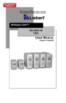
UPStation GXT™
700-3000 VA
230V
USER MANUAL
English / Deutsch / Français /
Italiano / Español
IMPORTANT SAFETY INSTRUCTIONS
WARNING: Do not attempt to service this product yourself except to replace
the battery. Opening or removing the cover may expose you to dangerous
voltages, even when the AC cord is disconnected from the electrical outlet.
Refer all servicing to qualified service personnel.
1.
SAVE THESE INSTRUCTIONS. THIS MANUAL CONTAINS IMPORTANT
SAFETY INSTRUCTIONS. Read all safety and operating instructions before
operating the Uninterruptible Power System (UPS). Adhere to all warnings
on the unit and in this manual. Follow all operating and user instructions.
2.
This product is designed for Commercial/Industrial use only. It is not
intended for use with life support and other designated “critical” devices.
Maximum load must not exceed that shown on the UPS rating label. If
uncertain, consult your dealer. See Limited Warranty.
3.
WHEN REPLACING THE BATTERIES, USE THE APPROPRIATE
LIEBERT-APPROVED REPLACEMENT BATTERY KIT. PROPER
DISPOSAL OF BATTERIES IS REQUIRED. REFER TO YOUR LOCAL
LAWS AND REGULATIONS FOR DISPOSAL REQUIREMENTS.
4.
Always turn off the UPS and unplug it before starting the battery
replacement procedure.
To replace batteries, refer to the battery
replacement procedure. If you feel unqualified to replace the batteries, do
not open the battery door. Refer all servicing to qualified service personnel.
5.
CAUTION: Do not open or mutilate the batteries. Released electrolyte is
harmful to skin and eyes and may be toxic.
6.
The mains supply socket or means of isolation must be within 2 meters of
the equipment and accessible to the operator. The UPS is designed for data
processing equipment.
7.
The UPS comes with two output power leads with molded connectors - do
not modify these leads. Consult dealer if connector does not match the load
socket. UPS must be grounded at all times while in use. Turn UPS off
before unplugging it, or the safety earth will be removed.
8.
The UPStation GXT™ models 700 VA, 1000 VA, 1500 VA, and 2000 VA are
not supplied with an input power lead for connection to the mains supply
socket. Use the input mains supply power lead from your data processing
equipment to connect the UPS to the mains supply. For the 3000 VA model,
use the supplied 16 ampere rated input mains supply lead. For UK supply
systems, consult a qualified electrician to connect the lead supplied for the
3000 VA model to the mains supply.
CAUTION: The UPS and the connected load combined total earth leakage
current must not exceed 3.5 milliamperes. If the connected load earth
leakage current is likely to exceed 2.0 milliamperes or you are unsure, then
convert the input lead attachment to either a fixed wiring installation or an
industrial plug/socket (e.g. CEE 17 connector). This task should be carried
out by a competent electrical engineer who is conversant with local electrical
codes/regulations.
2
9.
The UPS output supply sockets may be electrically live whenever the input
power lead is plugged into the mains supply socket. Turning the UPS off
does not electrically isolate the internal parts. To isolate the UPS, turn the
UPS off then isolate it from the mains supply.
10. When installing the UPS or making input and output connections, comply
with relevant safety standards (e.g. IEC950, VDE0805, EN50091-1).
11. This equipment complies with the requirements of the EMC Directive
89/336/EEC and the published technical standards. Continued compliance
requires installation in accordance with these instructions and the use of
manufacturer approved accessories with output cables not exceeding 10
metres (30 ft.) in length.
Use a shielded cable for the external
communications interface.
12. Operate UPS only from a properly earthed, 50 Hz or 60 Hz, 208-240 VAC
mains supply. Models are available for 100-127 VAC supply voltages.
13. Route power supply cords so they are not walked on or pinched.
14. Never block or insert any object into the ventilation holes or other openings.
Maintain a minimum clearance of 100 mm (4 inches) in front and rear of the
UPS for proper air flow and cooling.
15. Operate the UPS in an indoor environment only with an ambient temperature
range of 0° C to +40° C (32° F to +104° F). Install it in a clean environment,
free from moisture, flammable liquids, gasses, or corrosive substances.
16. Storing magnetic media on top of the UPS may result in data loss or
corruption.
17. Turn the UPS off and unplug the UPS before cleaning. Use only a soft cloth,
never liquid or aerosol cleaners.
18. This equipment can be operated by individuals without previous training.
3
INTRODUCTION AND SYSTEM DESCRIPTION
Congratulations on your choice of the UPStation GXT™ Uninterruptible Power
System (UPS). It provides conditioned power to microcomputers and other
sensitive electronic equipment.
Upon generation, AC power is clean and stable. However, during transmission
and distribution it may be subject to voltage sags, spikes, or complete power
failure which may interrupt computer operations, cause data loss, or even
damage equipment. The UPStation GXT™ protects equipment from these
disturbances.
The UPStation GXT™ comes in nominal power ratings of 700, 1000, 1500, 2000,
or 3000 VA. Complete specifications appear near the end of this section.
The UPStation GXT™ is a compact, “on-line” UPS.
An “on-line” UPS
continuously conditions and regulates its output voltage, whether the mains
power is present or not. It supplies connected equipment with clean sinewave
power. Sensitive electronic equipment operates best from sinewave power.
For ease of use, the UPStation GXT™ contains a light emitting diode (LED)
display to indicate either “load percentage” or “battery capacity” depending upon
the mode of operation. It also provides self-diagnostics, a combination On/Alarm
Silence/Manual Battery Test button, a combination Off/Bypass button, and two
levels of alarms when the unit is operating on battery.
The UPStation GXT™ has an interface port for communications between the
UPS and a LAN server or other computer system. This port provides detailed
operating information including voltages, currents, and alarm status to the host
system when used in conjunction with the SiteNet® 2 software. SiteNet® 2
software can also remotely control UPS operation.
GLOSSARY OF SYMBOLS USED ON PRODUCT
Indicates AC Input
Indicates AC Output
Indicates Caution: Note the accompanying instruction
indicates the position of a fuse
Indicates the position of a fuse
Requests the user to consult the manual for additional
information
Indicates that the unit contains a valve regulated lead acid
battery
4
MAJOR COMPONENTS
Dynamic
Bypass
Inverter
Rectifier/PFC
INPUT
TVSS
and
EMI/RFI
Filters
OUTPUT
DC to DC
Converter
Battery
Charger
Battery
TRANSIENT VOLTAGE SURGE SUPPRESSION (TVSS) AND EMI/RFI
FILTERS
These UPS components provide surge protection, and filter both electromagnetic
interference (EMI) and radio frequency interference (RFI). They minimize any
surges or interference present in the mains line and keep the sensitive
equipment protected.
RECTIFIER/POWER FACTOR CORRECTION (PFC) CIRCUIT
In normal operation, the rectifier/power factor correction (PFC) circuit converts
mains AC power to regulated DC power for use by the inverter, while ensuring
that the waveshape of the input current used by the UPS is near ideal.
Extracting this sinewave input current achieves two objectives: the mains power
is used as efficiently as possible by the UPS, and the amount of distortion
reflected on the mains is reduced. This results in cleaner power being available
to other devices in the building not being protected by the UPStation GXT™.
INVERTER
In normal operation, the inverter utilizes the DC output of the power factor
correction circuit and “inverts” it into precise, regulated sinewave AC power.
Upon a mains power failure, the inverter receives its required energy from the
battery through the DC-DC converter. In both modes of the operation, the UPS
inverter is on-line and continuously generating clean, precise, regulated AC
output power.
BATTERY CHARGER
The battery charger utilizes energy from the mains power and precisely regulates
it to continuously “float” charge the battery system. The battery system charges
whenever the UPStation GXT™ is plugged in.
5
DC TO DC CONVERTER
The DC-DC converter utilizes energy from the battery system and raises the DC
voltage to the optimum operating voltage for the inverter. This allows the inverter
to operate continuously at its optimum efficiency and voltage, thus increasing
reliability.
BATTERY
The UPStation GXT™ employs valve regulated, nonspillable, lead acid batteries.
At typical room temperatures and with the UPS float charging, the battery system
will last many years. Optional external battery cabinets are available to provide
extended run times for the rack-tower (RT) models. For battery run times, refer
to the Typical Battery Discharge Curves.
DYNAMIC BYPASS
The UPStation GXT™ provides an alternate path for mains power to the
connected load, in the unlikely event of a UPS malfunction. Should the UPS
have an overload, over temperature, or UPS failure condition, the UPS
automatically transfers the connected load to bypass. Bypass operation is
indicated by an alarm and an illuminated Bypass LED (other LED’s may be
illuminated to indicate the diagnosed problem). To manually transfer the
connected load from the inverter to bypass power, press the Off button once.
NOTE: The bypass power path does NOT protect the connected equipment
from disturbances on the mains supply.
GENERAL INSTALLATION
MINI-TOWER/TOWER UPS INSTALLATIONS
1.
Unpack the UPS carefully noting the packing method. Retain the box and
packing material for possible future shipment.
2.
CAUTION: The UPS is heavy (see specifications). Take proper precautions
when lifting or moving it.
3.
Visually inspect the UPS for freight damage. Report damage to the carrier
and your dealer.
4.
Locate the UPS indoors in a controlled environment, where it cannot be
accidentally disconnected. Locate it in an area with unrestricted airflow,
away from water, flammable liquids, gases, or corrosives. Maintain a
minimum of 100 mm (4 inches)
clearance
around
the
UPS.
Maintain an ambient temperature
range of 0° to 40° C (32° to 104° F).
NOTE:
UPS
operation
in
temperatures above 25° C (77° F)
reduces battery life. Ensuring load
equipment is turned off, plug all
loads into the UPS output sockets.
5.
For 700-2000 VA models, unplug
power input cable (A) from load
equipment input socket (D) and
plug it into UPS input socket (C).
6
Re-plug the power input cable (A) into mains supply socket. Proceed
with step 9.For 3000 VA models, a CEE 19 input cable is supplied. Proceed
with the next step.
6.
Connect the molded connector of the mains AC input supply cable into the
UPS.
7.
Fit the supplied retainer bracket around the input supply cable and secure
the bracket to the rear of the UPS using the two supplied screws.
8.
The free end of the input supply cable should be connected to the electrical
supply distribution system in accordance with local rules and conditions.
NOTE: The UPS On/Alarm Silence/Manual Battery Test button does not
electrically isolate the internal parts. To isolate the UPS, provide an isolator
that is accessible to the operator and located within two meters of the UPS.
The wires in the mains lead are colored with the following code:
Green and Yellow = Earth, Blue = Neutral, Brown = Live
As the color of the wires in the mains lead may not correspond with the
colored marking identifying the terminals in the plug, proceed as follows: The
green and yellow wire must be connected to the terminal in the plug that is
marked with the letter “E” or by the earth symbol, or colored green and
yellow. The blue wire must be connected to the terminal that is marked with
the letter “N” or colored black. The brown wire must be connected to the
terminal that is marked with the letter “L” or colored red.
9.
Connect the supplied CEE 22 output cable (B) between the load equipment
input socket (D) and one of the UPS AC output sockets (E). Connect all
load equipment to the UPS in this way.
10. Turn on the UPS by pressing the On button for at least one half second; then
turn on the connected load equipment. The UPS is ready for normal
operation.
Retainer
Bracket
Retainer
Bracket
Screws
Support
Base
7
RACK-MOUNT CONVERSION DIAGRAMS
RACK-MOUNT UPS CONVERSION AND INSTALLATION
1. Unpack the UPS carefully noting the packing method. Retain the box and
packing material for possible future shipment.
2.
CAUTION: The UPS is heavy (see specifications). Take proper precautions
when lifting or moving it.
3.
Visually inspect the UPS for freight damage. Report damage to the carrier
and your dealer.
4.
Remove the two screws located at the rear of the top cover with a Phillips
(cross head) screwdriver. Push the top cover towards back of UPS and lift
off. Remove and retain the two flange screws located at the front of UPS.
5.
Gently lay unit on its right side and remove the six rubber feet with the
screwdriver. Remove and retain screws from the two front feet.
NOTE: The rubber feet are not used for rack-mount installations.
6.
Locate securing flanges in the top of packing material and fasten to the UPS
using the flange screws from steps 4 and 5.
7.
Remove display template to change the orientation of the display. You may
also rotate the “Liebert UPStation GXT™” plate located at left of display
area.
8.
NOTE: UPS unit MUST be supported by a shelf, brackets or slide rails on
each side. The securing flanges WILL NOT support the weight of the UPS.
9.
For slide rail installations, securing hardware is provided with the UPS and is
located in the packing material (slide rails sold separately). Fasten the
slides into position with the screws per the instructions included with the
slide rails.
10. The UPS automatically starts up in the bypass mode once the UPS is
plugged into the mains socket. The UPS is now ready to be placed into the
equipment rack.
8
11. Ensure the load equipment is turned off, and plug all loads into the UPS
output sockets.
12. For 700-2000 VA models, unplug power input cable from load equipment
input socket and plug it into UPS input socket. Re-plug the power input
cable into mains supply socket. Proceed with step 16. For 3000 VA models,
a CEE 19 input cable is supplied. Proceed with the next step.
13. Connect the molded connector of the mains AC input supply cable into the
UPS.
14. Fit the supplied retainer bracket around the input supply cable and secure
the bracket to the rear of the UPS using the two supplied screws.
15. The free end of the input supply cable should be connected to the electrical
supply distribution system in accordance with local rules and conditions.
Note: The UPS On/Alarm Silence/Manual Battery Test button does not
electrically isolate the internal parts. To isolate the UPS, provide an isolator
that is accessible to the operator and located within two meters of the UPS.
The wires in the mains lead are colored with the following code:
Green and Yellow = Earth, Blue = Neutral, Brown = Live
As the color of the wires in the mains lead may not correspond with the
colored marking identifying the terminals in the plug, proceed as follows:
The green and yellow wire must be connected to the terminal in the plug that
is marked with the letter “E” or by the earth symbol, or colored green and
yellow. The blue wire must be connected to the terminal that is marked with
the letter “N” or colored black. The brown wire must be connected to the
terminal that is marked with the letter “L” or colored red.
16. Connect the supplied CEE 22 output
cable between the load equipment
input socket and one of the UPS AC
output sockets. Connect all load
equipment to UPS in this way.
17. Turn on the UPS by pressing the On
button; then turn on the connected
load equipment. The UPS is ready
for normal operation.
Retainer
Bracket
Screws
9
OPTIONAL BATTERY CABINET(S) INSTALLATION
Up to two optional battery cabinets may be connected to the UPS to provide
additional run time. Battery cabinets are designed to be placed on either side or
beneath the UPS.
1.
2.
3.
4.
5.
6.
7.
Unpack the UPS battery cabinet(s) carefully noting the packing method.
Retain the box and packing material for possible future shipment.
CAUTION: The battery cabinet(s) are heavy (see specifications). Take
proper precautions when lifting or moving them.
Visually inspect the UPS for freight damage. Report damage to the carrier
and your dealer.
Follow the same installation instructions used earlier for the UPS (tower or
rack-mount).
Attach external battery cabinets as shown, using the enclosed metal
securing plate to prevent tip-over.
Connect the supplied cable to the battery cabinet then to the UPS.
Turn on the breaker on the rear of the battery cabinet.
Battery Cabinet Installation Diagram
SECURING PLATE
BREAKER
10
FERRITE BEAD INSTALLATION
Serial Communications
Attach the smaller enclosed ferrite bead
clamp to the communication cable as
shown in the drawing using the following
directions:
•
•
•
•
Open the ferrite bead.
Place the communication cable inside
the ferrite bead grove.
Position the ferrite beads as close as
possible to the end of the cable that
connects to the DB9 connector of the
UPS.
Close the ferrite bead so that the
ferrite bead’s case snaps closed with
the cable routed inside the ferrite
bead’s case.
SNMP Installation
Attach the larger enclosed ferrite bead
clamp to the network cable as shown in
the drawing using the following directions:
•
•
•
•
•
Open the ferrite bead.
Place the network cable inside the
ferrite bead grove.
Wrap the cable once around the
bead.
Position the ferrite cable as close as
possible to the end of the cable that
connects to the UPS.
Close the ferrite bead so that the
ferrite bead’s case snaps closed with
the cable routed inside the ferrite
bead’s case.
11
UPSTATION GXT™
Fault Indicator
Bypass Indicator
UPS On Indicator
Battery Indicator
AC Input Indicator
Load/Battery Level
Indicators
On/Alarm Silence/
Manual Battery Test
Button
Off/ Bypass Button
1- Output Receptacles
2- DB-9 Interface Port
3- AC Inlet
4- Intellislot TM
Communications Port
5- Circuit Protector or fuse
6- Output Voltage Selector
Switches
7- Battery Cable Connector
6
2
4
6
2
4
6
2
4
5
6
2
4
3
3
5
3
5
5
7
7
7
1
3
1
3
700/1000 VA
Mini-Tower
1000/1500 VA
Rack Tower
2000 VA
Rack Tower
12
3000 VA
Rack Tower
CONTROLS AND INDICATORS
On/Alarm Silence/Manual Battery Test Button
This button controls output power to connected load(s) and has three functions:
On, Alarm Silence, and Manual Battery Test. Pressing this button will start up
the UPS in order to provide conditioned and protected power into the mains
socket.
To silence alarms, press this button for at least one half second while alarm
conditions are present. After the alarm is silenced, the UPStation GXT™ will
reactivate the alarm system to alert of additional problems.
NOTE: The low battery and bypass reminder alarms cannot be silenced.
To initiate a manual battery test, press this button for at least one half second
while operating from mains power and no alarm conditions are present. If the
bottom two LEDs do not illuminate during a Battery Test, allow the UPS to
recharge the batteries for 24 hours. After 24 hours, retest the batteries. If the
batteries have been retested and the bottom two LEDs still do not illuminate,
contact your dealer or Liebert Technical Support (LTS) for a battery replacement
kit.
Off/Bypass Button
This button controls output power to connected load(s) and has dual functions:
Off and Bypass.
CAUTION: Pressing this button once will cause the load to be transferred to
bypass power. Pressing this button a second time within 4 seconds will result in
loss of power to the output sockets and connected loads. Perform all necessary
shutdown procedures on connected loads before pressing this button twice.
Load/Battery Level Indicators (4 Green, 1 Amber)
The Load/Battery Level indicators have dual functions. During normal mode
operation LED indicators display the approximate electrical load placed upon the
UPS; and during battery mode operation LED indicators display approximate
battery capacity. Refer to the Typical Battery Discharge Curves to determine the
approximate amount of back up time with respect to your connected load
percentage.
The UPStation GXT™ is equipped with automatic and remote battery test
features. The automatic test occurs every 14 days if mains has not been
interrupted (14 day timer resets if unit goes to battery). Should the battery fail
this test, the fault indicator along with the A and C diagnostic LEDs will illuminate
and an alarm will sound (refer to Troubleshooting Guide). The remote test
feature functions with either SiteNet® 2 or SiteNet® SNMP Manager software
and can remotely initiate the battery test.
Fault Indicator (Red)
The Fault indicator is illuminated if the UPS has detected a problem. Also, one or
more of the load/battery level indicators may be illuminated (refer to
Troubleshooting Guide).
Bypass Indicator (Amber)
The Bypass indicator is illuminated when the UPS is operating from bypass
power. An alarm will sound indicating the UPS detected a problem, or the
manual bypass function has been activated.
13
UPS On Indicator (Green)
The UPS On indicator is illuminated when the UPS inverter is operating and
supplying power to your connected loads.
Battery Indicator (Amber)The Battery indicator is illuminated when the UPS is
operating from the battery system.
AC Input Indicator (Green)
The AC Input indicator is illuminated when mains power is available and within
the input specification.
Output Voltage Selector Switches
The Output Voltage Selector Switches, located on the rear of the UPS, are
designed to allow selecting or changing the desired output voltage to match the
mains. The settings to choose from are 208, 220, 230, and 240 VAC output. The
factory default setting is 230 VAC.
NOTE: Never change the switch settings while UPS is on and powering
connected loads. Switch positions for voltages:
208 VAC
220 VAC
230 VAC
240 VAC
NOTE: Setting output voltage to 208 VAC will cause UPS unit to be derated to
90% of the VA and Watt rating listed in specification section.
OPERATION
NORMAL MODE OPERATION
During normal operation, mains power provides energy to the UPS. The filters,
the power factor conditioning circuit and the inverter process this power to
provide computer grade power to connected loads. The UPS maintains the
batteries in a fully charged state.
The four green LEDs indicate an approximate level of load in 25% increments. If
the UPS becomes loaded beyond full rating, the fifth (amber) LED indicator will
illuminate and sound an alarm.
The display template indicates the percentage of load on the UPS output. Figure
1 displays approximately 51-75% loading.
Fault
!
100%
BYPASS
76-100%
UPS
ON
51-75%
26-50%
BATTERY
AC
INPUT
0-25%
Figure 1- Normal Mode Operation at 51-75% loading
14
BATTERY MODE OPERATION
Battery mode occurs in event of an extreme input voltage condition or complete
mains failure. The battery system supplies power through the DC-DC converter
to the inverter to generate power for the connected load.
During battery mode an alarm sounds every 10 seconds. This will change to 2
beeps every 5 seconds when battery runs low (approximately 2 minutes
remaining). The AC Input LED will extinguish, and the Battery LED will illuminate
to warn that a mains problem has occurred. Each load/battery level indicator
represents a 20% capacity level. As capacity decreases, fewer indicators remain
illuminated. Refer to the Troubleshooting Guide.
For battery run times, refer to the Typical Battery Discharge Curves. To increase
this time, turn off non-essential pieces of equipment (such as idle computers and
monitors) or add the optional external battery cabinet.
NOTE: External battery cabinets can only be added to rack-tower (RT) models.
CAUTION: Turning off the UPS while in battery mode will result in loss of output
power.
Figure 2 displays approximately 61-80% battery capacity remaining.
BATTERY RECHARGE MODE
Once mains power is restored, the UPS resumes normal operation. At this time,
the Battery Charger begins recharging the battery.
!
Fault
20-0%
BYPASS
40-21%
UPS
ON
60-41%
BATTERY
80-61%
AC
INPUT
100-81%
Figure 2 – Battery Mode Operation at 61-80% battery capacity
15
COMMUNICATIONS INTERFACE PORT
The UPStation GXT™ UPS contains a standard DB-9 female connector located
on the rear of the UPS unit. Several signals are provided on this port and are
assigned as follows:
PIN
1
2
3
4
5
6
7
8
9
ASSIGNMENT DESCRIPTION
Low Battery (open collector)
UPS TxD (typical RS-232 levels)
UPS RxD (typical RS-232 levels)
Remote Shutdown (5-12V); battery operation
Common
Remote Shutdown (short to pin 5); all modes of operation
Low Battery (open emitter)
Mains Fail (open emitter)
Mains Fail (open collector)
PIN ASSIGNMENT
COLLECTOR TO EMITER*
Open Collector
(+)
330 Ohms
(-)
Open Emitter
*Maximum voltage and current on pins 1,7,8,9 is 80V DC; 10.0 mA.
UPS MONITORING
The UPStation GXT™ UPS has the capability of being monitored with stand
alone computers, network workstations, network servers, or UNIX hosts via the
DB-9 female connector located on the rear of the UPS.
This capability is used in applications requiring the UPS to provide status and
power monitoring information to the computer system. For example, during a
mains power failure, the information can be used by the computer’s operating
system or application program to automatically save information in buffers, to
close files, and shut down operations prior to battery capacity depletion.
Monitoring of the UPS via a computer system is easily made with a Liebert
SiteNet® 1 shutdown kit (sold separately).
Consult your local Liebert
representative to determine the correct software kit for your application. The kit
includes special purpose cable and shutdown software.
16
UPS INTELLIGENT COMMUNICATIONS
The UPStation GXT™ UPS has the capability to communicate intelligently with
stand alone computers, network workstations, network servers, or UNIX hosts via
the DB-9 female connector located at the rear of the UPS. By purchasing the
optional Liebert SiteNet® 2 software package (sold separately), intelligent
communications allows the following capabilities:
Quantitative monitoring of mains and UPS power
Quantitative monitoring of internal UPS parameters
Periodic tests of battery quality and replacement notification
Timed and delayed shutdown of the UPS
Logging of power disturbances and anomalies
Consult your local Liebert sales representative for more information about
SiteNet® 2 software.
UPS INTELLISLOT™ COMMUNICATIONS
The UPStation GXT™ UPS contains an Intellislot™ communications port for the
optional internal Ethernet SNMP card. Optional SiteNet® SNMP Manager
software is available to allow communication through several network
management systems. Contact your local Liebert representative, dealer, or
reseller.
CAUTION:
TO MAINTAIN SAFETY (SELV) BARRIERS AND FOR
ELECTROMAGNETIC COMPATABILITY, SIGNAL CABLES SHOULD BE
SEGREGATED AND RUN SEPARATE FROM ALL OTHER POWER CABLES,
WHERE APPLICABLE.
MAINTENANCE
The UPStation GXT™ UPS requires very little maintenance. The batteries are
valve regulated, nonspillable, lead acid, and should be kept charged to obtain
their designed life. The UPS continuously charges the batteries when connected
to the mains supply.
When storing the UPS for any length of time, it is recommended to plug the UPS
in for at least 24 hours every four to six months to ensure full recharge of the
batteries.
The UPStation GXT™ UPS is designed to allow the user to safely replace the
batteries. Read the safety cautions before proceeding. Contact your dealer to
obtain the appropriate replacement battery kit.
17
BATTERY REPLACEMENT PROCEDURES
CAUTION – A battery can present a risk of electrical shock and high short circuit
current. The following precautions should be observed before replacing the
batteries:
Turn off and disconnect the UPS from the mains power prior to opening the
battery replacement door.
Remove rings, watches, and other metal objects.
Use a Phillips (cross head) screwdriver with insulated grips.
Do not lay tools or other metal objects on top of the batteries.
If the battery replacement kit is damaged in any way or shows signs of
leakage, contact your dealer immediately.
Do not dispose of batteries in a fire, the batteries may explode.
If you feel unqualified to replace the batteries, do not open the battery door.
Call Liebert Technical Support (LTS). World Wide Technical Support
numbers are located at the end of this section.
MINI-TOWER BATTERY REPLACEMENT
Battery connector
Battery door screws
FOR 700/1000 VA MINI-TOWER MODELS:
1. Gently lay the UPS on its right side.
2. Loosen and remove the five screws on the battery door. Remove the door
by sliding it toward the rear of UPS and lifting it off. Lay the battery door
aside for reassembly.
3. Gently pull battery wiring out and disconnect the battery connector.
4. Grasp the battery assembly, and pull it out of the UPS.
5. Unpack the new battery assembly taking care not to destroy the packing.
Compare new and old battery assemblies to make sure they are the same
quantity and voltage rating (see specifications). If so, proceed with step 6;
otherwise STOP and contact your dealer or LTS.
6. Slide the new battery assembly into the cavity, noting the connector is facing
outward. Connect the battery connector together.
NOTE: There will be a small spark when connecting the battery connector.
This is normal and will not harm you or the UPS.
7. Replace battery door by inserting the three metal tabs into the slots and
pushing it toward the front of the UPS. Replace and tighten the five screws
to lock the battery door closed.
18
8.
9.
Carefully stand the UPS upright. Connect the UPS to the mains supply
socket and turn on the UPS by pressing the on button. The UPS is ready for
normal operation.
Dispose of batteries in accordance with your local laws and regulations.
FOR 1000 TO 3000 VA RACK/TOWER MODELS:
CAUTION: The battery assembly is heavy. Take proper precautions when lifting
or moving it.
TOWER MODELS ONLY:
Remove top cover by removing the two screws located on rear of top cover.
Push the top cover towards the back of UPS and lift off. Remove the two
flange screws near the front of UPS.
Gently lay the UPS on its right side and remove the two front rubber feet.
Continue with Rack/Tower Models battery replacement procedures.
RACK/TOWER MODELS:
1. Grasp the front bezel (cover) and pull forward for removal.
NOTE: The two securing flanges must be removed before front bezel
(cover) can be removed.
2. Remove the two screws from the small battery door. Remove the door by
pulling it forward and lifting it off. Lay aside for reassembly.
NOTE: For 2000/3000 VA models, the small door contains a connector that
disconnects battery into a lower, safer voltage.
3. Loosen the five screws of the large battery door. Remove the door by
pulling it forward and lifting it off. Lay aside for reassembly.
4. Pull battery assembly out approximately 50mm (2 in). Gently pull the battery
wiring out and disconnect the battery connector.
5. Completely remove battery assembly from the UPS.
6. Unpack the new battery assembly taking care not to destroy the packing.
Compare new and old battery assemblies to make sure they are the same
quantity and voltage rating (see specifications). If so, proceed with the next
step; otherwise STOP and contact your dealer or LTS.
7. Slide the new battery assembly into the cavity, leaving 50mm (2 in).
8. Connect the battery wire connectors together.
NOTE: On 1000/1500 VA models, there will be a small spark when
connecting the connectors. This is normal and will not harm you or the UPS.
9. Slide battery assembly completely into the UPS, reposition the large battery
door and replace the screws removed in step 3.
10. Reposition small battery door and replace the screws removed in step 2 to
lock top battery door closed. On 2000/3000 VA models, make sure the top
door connection is made.
11. Replace front bezel (cover) on UPS. Replace the securing flanges (for Rack
Tower procedures) and flange screws to secure bezel in place. For Tower
procedures, replace the two front rubber feet, stand unit upright, and replace
the top cover. Connect the UPS to the mains supply socket and turn on the
UPS by pressing the On button. The UPS is ready for normal operation.
12. Dispose of batteries in accordance with your local laws and regulations.
19
RACK / TOWER BATTERY REPLACEMENT
Top cover
screws
Flange
screws
Rear View
Aerial View
w/top cover removed
Two front
rubber feet
Front bezel (cover)
Small battery door
Large battery
door
Screw hidden by
small battery door
Large battery door
20
Battery connector
UPSTATION GXT BATTERY RUN TIMES
(Discharge times are at 25° C ambient)
Internal Battery (minutes)
Load%
700MT
1000MT
1000RT
1000RTE
1500RT
2000RT
3000RT
10%
20%
30%
40%
50%
60%
70%
80%
90%
100%
52
40
32
24
18
15
12
10
8
6
94
45
33
24
18
14
12
9
7
6
94
45
33
24
18
14
12
9
7
6
169
127
94
68
49
36
28
23
19
17
78
39
27
20
15
11
9
7
6
5
160
83
47
34
27
21
18
15
13
11
101
51
28
20
15
12
10
8
7
6
Internal Battery + 1 External Battery Cabinet (minutes)
Load%
700MT
1000MT
1000RT
1000RTE
1500RT
2000RT
3000RT
10%
20%
30%
40%
50%
60%
70%
80%
90%
100%
N/A
N/A
N/A
N/A
N/A
N/A
N/A
N/A
N/A
N/A
N/A
N/A
N/A
N/A
N/A
N/A
N/A
N/A
N/A
N/A
479
255
150
110
85
66
56
48
41
35
552
335
210
152
115
88
72
62
52
45
408
215
126
95
75
57
48
40
35
29
343
204
133
100
77
60
50
43
36
31
273
140
78
57
44
35
30
26
22
18
Internal Battery + 2 External Battery Cabinets (minutes)
Load%
700MT
1000MT
1000RT
1000RTE
500RT
2000RT
3000RT
10%
20%
30%
40%
50%
60%
70%
80%
90%
100%
N/A
N/A
N/A
N/A
N/A
N/A
N/A
N/A
N/A
N/A
N/A
N/A
N/A
N/A
N/A
N/A
N/A
N/A
N/A
N/A
848
425
243
196
168
133
109
89
77
66
920
505
303
238
198
155
125
103
88
76
718
365
208
164
139
112
94
78
68
58
623
345
211
156
120
94
81
70
62
54
444
236
138
100
75
59
50
43
36
31
21
FUSE REPLACEMENT PROCEDURES
CAUTION: Before changing the input fuse, turn off the UPS, and unplug the
supply lead from the AC input supply and from the UPS. Replace the fuse with
the same type and rating.
Insert flat blade
screwdriver into slot
and turn fuse holder
to remove / install
Input Fuse
Fuse Holder
Remove
Install
1.
Remove the fuse holder by inserting a flat blade screwdriver into the slot and
turning to remove as indicated in the figure above.
2. Remove the input fuse.
3. Locate the spare input fuse that is included with the UPS.
4. Insert the spare fuse into the fuse holder, and reinstall assembly into the
UPS. Using the screwdriver, rotate clockwise until fuse holder locks into
position.
5. Reconnect the input power lead to the UPS, and the input power lead to the
input AC supply.
6. Restart the UPS. The UPS is ready for normal operation.
NOTE: For 1500 VA, 2000 VA, and 3000 VA units, reset circuit protector.
AUDIBLE ALARM CONDITIONS
CONDITION
Battery mode
(utility failure)
Low battery
Output overload (bypass)
Over temperature (bypass)
DC Bus overvoltage (bypass)
Control power supply failure (bypass)
PFC failure (bypass)
Inverter failure
Battery Test failure
ALARM
One short beep every ten seconds; more
than two minutes of run time remaining
Two short beeps every five seconds; less
than two minutes of run time remaining
One short beep every half second
One second beep every four seconds
One second beep every four seconds
One second beep every four seconds
One second beep every four seconds
One second beep every four seconds
Two second beep every minute
22
TROUBLESHOOTING
The information below indicates various symptoms a user may encounter in the
event the UPStation GXT™ develops a problem. Use this information to
determine whether external factors cause the problem and how to remedy the
situation.
1.
2.
3.
The fault indicator will illuminate indicating the UPS detected a problem.
An alarm will sound, alerting that the UPS requires attention.
One or more additional load/battery level LED indicators will be illuminated
to provide a diagnostic aid to the operator, as described below:
!
Fault
E
BYPASS
D
UPS
ON
C
BATTERY
B
AC
INPUT
A
All.
A.
B.
C.
D.
E.
A&C.
C&E.
Load / Battery
Level Indicators
On bypass due to output overload (beep every half second)
On bypass due to over temperature condition (beep every 4 seconds)
On bypass due to DC bus overvoltage (beep every 4 seconds)
On bypass due to control power supply failure (beep every 4 seconds)
On bypass due to PFC failure (beep every 4 seconds)
On bypass due to inverter failure (beep every 4 seconds)
UPS failed battery test (long beep every minute)
UPS shutdown due to command from communication port (SNMP); no beep
The fault indicators will be illuminated indefinitely while battery charger is
operational, or for a maximum of 5 minutes while battery charger is not
operational. If a problem persists consult your dealer, or contact Liebert
Technical Support (LTS). World Wide Technical Support numbers are located at
the end of this section.
23
TROUBLESHOOTING GUIDE
PROBLEM
UPS fails to start when
on button is pressed
Battery indicator is
illuminated
CAUSE
SOLUTION
UPS is short circuited or
overloaded
Internal fuse is blown,
indicating internal fault
UPS not plugged in
UPS input protection has
opened
Mains voltage out of UPS
input range.
UPS has reduced battery
time
Batteries not fully charged
UPS is overloaded
Fault and Bypass
indicators and all load
level LEDs are
illuminated
Batteries may not be able to
hold a full charge due to age
UPS overloaded or load
equipment is faulty
Fault and Bypass
indicators and diagnostic
LED A are illuminated
UPS internal fan has a
problem or UPS shutdown
due to temperature condition.
Load is on bypass power
Fault and Bypass
indicators and diagnostic
LED B are illuminated
Fault and Bypass
indicators and diagnostic
LED C are illuminated
Fault and Bypass
indicators and diagnostic
LED D are illuminated
Fault and Bypass
indicators and diagnostic
LED E are illuminated
Fault and Bypass
indicators and diagnostic
LED A & C are
illuminated
Fault and Bypass
indicators and diagnostic
LED C & E are
illuminated
UPS internal DC bus
overvoltage
Ensure UPS is off. Disconnect all loads
and ensure nothing is lodged in output
sockets. Ensure loads are not defective
or shorted internally.
Do not attempt to open or service the
UPS. Contact your dealer or LTS.
UPS is operating from battery mode,
make certain UPS is securely plugged
into the wall socket
UPS is operating from battery mode.
Save data and close applications.
Replace UPS input fuse or reset input
breaker, then restart UPS.
UPS is operating from battery mode.
Save data and close applications.
Ensure mains supply voltage is within
acceptable limits for UPS.
Keep UPS plugged in continuously at
least 24 hours to recharge batteries
Check load level display and reduce load
level
Replace batteries. Contact your dealer
or LTS for replacement battery kit
Check load level display and remove
non-essential loads. Recalculate load
VA and reduce number of loads
connected to UPS. Check load
equipment for faults.
Ensure UPS is not overloaded,
ventilation openings not blocked, or room
ambient temperature not excessive.
Wait 30 minutes to allow UPS to cool,
then restart UPS. IF it does not restart,
contact your dealer or LTS.
UPS requires service. Contact your
dealer or LTS.
UPS power control fault.
UPS requires service. Contact your
dealer or LTS.
UPS PFC fault.
UPS requires service. Contact your
dealer or LTS.
UPS inverter fault.
UPS requires service. Contact your
dealer or LTS.
UPS failed the battery test.
Replace batteries. Contact your dealer
or LTS.
UPS shutdown due to a
command from the
communications port(s)
Your UPS has received a signal or
command from the attached computer. If
this was inadvertent, ensure the
communication cable used is correct for
your system. For assistance, contact
your dealer or LTS.
24
SPECIFICATIONS
MODEL NUMBER
GXT700MT-230
GXT1000MT-230
MODEL RATING VA/W
700 / 490
1000 / 700
DIMENSIONS: mm (in)
Unit
162 x 430 x 225
162 x 430 x 225
WxDxH
(6.4 x 15.6 x 8.9)
(6.4 x 15.6 x 8.9)
Shipping
280 x 502 x 362
280 x 502 x 362
WxDxH
(11.0 x 19.75 x 14.25)
(11.0 x 19.75 x 14.25)
WEIGHT: kg (lbs)
Unit
13.1 (28.8)
15.8 (34.8)
Shipping
15.0 (33.0)
17.7 (39.0)
INPUT AC PARAMETERS
Voltage Range (typical)
230 VAC nominal; variable based upon output load
100% - 70% Loading
160-163 VAC to 273-276 VAC
70% - 30% Loading
140-143 VAC to 273-276 VAC
30% - 0% Loading
120-122 VAC to 273-276 VAC
Frequency
48.1 - 51.9 Hz or 57.6 - 62.4 Hz; auto sensing
Input connector
IEC320-10A
IEC320-10A
OUTPUT AC PARAMETERS
Output Sockets
(4) IEC320-10A
(4) IEC320-10A
Voltage
208/220/230/240 (switch selectable) VAC; ±3%
Frequency
50 Hz or 60Hz
Waveform
Sinewave
Main Mode Overload
200% for 8 cycles; 130% for 10 seconds with transfer to bypass
BATTERY PARAMETERS
Type
Valve-regulated, nonspillable, lead acid
Qty. x Voltage x Rating
2 x 12V x7 or 7.2 AH
3 x 12V x 7 or 7.2 AH
Back-up Time
See Typical Battery Discharge Curves
ENVIROMENTAL
Operating Temperature
0° C to +40° C (+32° F to +104° F)
Storage Temperature
-15° C to +50° C (+5° F to +122 °F)
Relative Humidity
0% to 95%, non-condensing
Operating Elevation
Up to 3000 m (10,000 ft.) at 40° C without derating
Storage Elevation
15.000 m (50,000 ft.) maximum
Audible Noise
<45 dBA, at 1 meter
AGENCY
Safety
EN50091-1, TUV/GS Listed, CE Low Voltage Directive compliant
RFI/EMI
EN55022, Class B; CE EMC Directive compliant
IEC 801-2, Level 4 / IEC 801-3, Level 3 / IEC 801-4,
Immunity
Level 4 / IEC801-5,Level 3
25
SPECIFICATIONS
MODEL NUMBER
GXT1000RT-230
GXT1000RTE-230
MODEL RATING VA/W
1000 / 700
1000 / 700
DIMENSIONS: mm (in)
Unit
177 x 522 x 430
177 x 522 x 430
WxDxH
(7.0 x 19.3 x 16.9)
(7.0 x 19.3 x 16.9)
Shipping
340 x 660 x 565
340 x 660 x 565
WxDxH
(13.38 x 26.0 x 22.25)
(13.38 x 26.0 x 22.25)
WEIGHT: kg (lbs)
Unit
23.6 (51.9)
31.1 (68.4)
Shipping
26.8 (59.0)
34.3 (75.5)
INPUT AC PARAMETERS
Voltage Range (typical)
230 VAC nominal; variable based upon output load
100% - 70% Loading
160-163 VAC to 273-276 VAC
70% - 30% Loading
140-143 VAC to 273-276 VAC
30% - 0% Loading
120-122 VAC to 273-276 VAC
Frequency
48.1 - 51.9 Hz or 57.6 - 62.4 Hz; auto sensing
Input connector
IEC320-10A
IEC320-10A
OUTPUT AC PARAMETERS
Output Sockets
(4) IEC320-10A
(4) IEC320-10A
Voltage
208/220/230/240 (switch selectable) VAC; ±3%
Frequency
50 Hz or 60Hz
Waveform
Sinewave
Main Mode Overload
200% for 8 cycles; 130% for 10 seconds with transfer to bypass
BATTERY PARAMETERS
Type
Valve-regulated, nonspillable, lead acid
Qty. x Voltage x Rating
3 x 12V x 7 or 7.2 AH
6 x 12V x 7 AH
Back-up Time
See Typical Battery Discharge Curves
ENVIROMENTAL
Operating Temperature
0° C to +40° C (+32° F to +104° F)
Storage Temperature
-15° C to +50° C (+5° F to +122 °F)
Relative Humidity
0% to 95%, non-condensing
Operating Elevation
Up to 3000 m (10,000 ft.) at 40° C without derating
Storage Elevation
15.000 m (50,000 ft.) maximum
Audible Noise
<50 dBA, at 1 meter
AGENCY
Safety
EN50091-1, TUV/GS Listed, CE Low Voltage Directive compliant
RFI/EMI
EN55022, Class B; CE EMC Directive compliant
IEC 801-2, Level 4 / IEC 801-3, Level 3 / IEC 801-4, Level 4 / IEC801Immunity
5,Level 3
26
SPECIFICATIONS
MODEL NUMBER
GXT1500RT-230
GXT2000RT-230
GXT3000RT-230
MODEL RATING VA/W
1500 / 1050
2000 / 1400
3000 / 2100
DIMENSIONS: mm (in)
Unit
177 x 522 x 430
177 x 522 x 430
177 x 522 x 430
WxDxH
(7.0 x 19.3 x 16.9)
(7.0 x 19.3 x 16.9)
(7.0 x 19.3 x 16.9)
Shipping
340 x 660 x 565
340 x 660 x 565
340 x 660 x 565
WxDxH
(13.38 x 26.0 x 22.25)
(13.38 x 26.0 x 22.25)
(13.38 x 26.0 x 22.25)
WEIGHT: kg (lbs)
Unit
27.7 (60.9)
36.8 (80.9)
39.0 (85.9)
Shipping
30.9 (68.0)
40.0 (88.0)
42.3 (93.0)
INPUT AC PARAMETERS
Voltage Range (typical)
230 VAC nominal; variable based upon output load
100% - 90% Loading
184-187 VAC to 273-276 VAC
90% - 70% Loading
160-163 VAC to 273-276 VAC
70% - 30% Loading
140-143 VAC to 273-276 VAC
30% - 0% Loading
120-122 VAC to 273-276 VAC
Frequency
48.1 - 51.9 Hz or 57.6 - 62.4 Hz; auto sensing
Input connector
IEC320-10A
IEC320-10A
IEC320-16A
OUTPUT AC PARAMETERS
Output Sockets
(4) IEC320-10A
(4) IEC320-10A
(4) IEC320-10A;
(1) IEC320-16A
Voltage
208/220/230/240 (switch selectable) VAC; ±3%
Frequency
50 Hz or 60Hz
Waveform
Sinewave
Main Mode Overload
200% for 8 cycles; 130% for 10 seconds with transfer to bypass
BATTERY PARAMETERS
Type
Valve-regulated, nonspillable, lead acid
Qty. x Voltage x Rating
4 x 12V x 7 or 7.2 AH
8 x 12V x 6.5 or 7.0 AH
8 x 12V x 7 or 7.2 AH
Back-up Time
See Typical Battery Discharge Curves
ENVIROMENTAL
Operating Temperature
0° C to +40° C (+32° F to +104° F)
Storage Temperature
-15° C to +50° C (+5° F to +122 °F)
Relative Humidity
0% to 95%, non-condensing
Operating Elevation
Up to 3000 m (10,000 ft.) at 40° C without derating
Storage Elevation
15.000 m (50,000 ft.) maximum
Audible Noise
<50 dBA, at 1 meter
AGENCY
Safety
EN50091-1, TUV/GS Listed, CE Low Voltage Directive compliant
RFI/EMI
EN55022, Class B; CE EMC Directive compliant
IEC 801-2, Level 4 / IEC 801-3, Level 3 / IEC 801-4, Level 4 / IEC801-5,Level 3
Immunity
27
BATTERY CABINET SPECIFICATIONS
MODEL NUMBER
GXT36VBATT
GXT48VBATT
Used w/ UPS Model
1000RT
1500RT
DIMENSIONS: in (mm)
Unit
177 x 522 x 430
177 x 522 x 430
WxDxH
(7.0 x 19.3 x 16. 9)
(7.0 x 19.3 x 16. 9)
Shipping
13.38 x 26.0 x 22.25
13.38 x 26.0 x 22.25
WxDxH
(340 x 660 x 565)
(340 x 660 x 565)
WEIGHT: lbs (kg)
Unit
61.3 (27.9)
71.6 (32.5)
Shipping
68.4 (31)
78.7 (35.7)
BATTERY PARAMETERS
Type
Valve-regulated, nonspillable, lead
# of Strings x Qty/Str. x
Batt. Voltage x Batt. Rating
Batt. Mfg./ Part #
Back-up Time
Recharge Time
ENVIROMENTAL
Operating Temperature
Storage Temperature
Relative Humidity
Operating Elevation
Storage Elevation
AGENCY
Safety
RFI/EMI
Immunity
2x3x12Vx7.0 or 7.2 AH
2x4x12Vx7.0 or 7.2 AH
GXT96VBATT
2000RT/3000RT
177 x 522 x 430
(7.0 x 19.3 x 16. 9)
13.38 x 26.0 x 22.25
(340 x 660 x 565)
71.6 (32.5)
78.7 (35.7)
acid
1x8x12Vx7.0 or 7.2
AH
CSB GP1270F2 or Panasonic LC-R127R2CH1
See Typical Battery Discharge Curves
5 Hours to 95% capacity after full discharge into 100% load
+32° F to +104° F (0° C to +40° C)
+5° F to +122 °F (-15° C to +50° C)
0% to 95%, non-condensing
Up to 10,000 ft. (3000 m) at 40° C without derating
50,000 ft. (15.000 m) maximum
UL 1778, c-UL Listed; TUV, CE LVD compliant
FCC Part 15, Subpart B, Class A; EN5022 Class B; CE ECM compliant
IEEE 587 Category A; IEC 801-2, Level 4;
IEC801-3, Level 3
IEC801-4, Level 4
IEC801-5, Level 3
28
LIMITED WARRANTY
Liebert Corporation extends the following LIMITED WARRANTY to the
purchaser and to its customer (collectively referred to as the "Purchaser"): the
enclosed Uninterruptible Power System (UPS) and components are free from
defects in materials and workmanship under normal use, service, and
maintenance FOR A PERIOD OF TWO YEARS FROM THE DATE OF
ORIGINAL PURCHASE from Liebert or the Liebert dealer or retailer. THE
FOREGOING WARRANTY IS THE ONLY WARRANTY GIVEN AND NO
OTHER WARANTY IS PROVIDED, EXPRESS OR IMPLIED, INCLUDING
WITHOUT LIMITATION, MERCHANTABILITY OR FITNESS FOR A
PARTICULAR PURPOSE. Certain aspects of disclaimers are not applicable to
consumer products acquired by individuals and used for personal, family, or
household purposes (as distinguished from industrial or other purposes). Local
laws may not allow limitations on how long an implied warranty lasts, so the
above limitation may not apply to you. This warranty gives you specific legal
rights, and you may have other rights which vary according to local law.
Certain repairs or services are the responsibility of the Purchaser and the
Purchaser is expected to pay for them. This warranty does not extend either to
products with removed or altered serial numbers or to any losses or damages
due to act of God or source external to the product, misuse, accident, abuse,
neglect, negligence, unauthorized modification, alteration, or repair, use beyond
rated capacity, or improper installation, maintenance, application or use,
including, without limitation, use in a manner contrary to the accompanying
instructions or applicable codes. WARNING: Warranty is void if the battery is
allowed to discharge below the minimum battery cutoff point. To prevent such
discharge DO NOT leave the unit power switch "ON" for more than two (2) days
without AC power being supplied to the UPS. The battery must be recharged
every four (4) to six (6) months when not in use.
If the UPS fails to conform with the above warranty within the two year warranty
period, Liebert will repair or replace the UPS, at Liebert's option. Repairs or
replacements are warranted for the remainder of the original warranty period.
Purchaser, to make a warranty claim, should call +44 (0)1793 553355 to obtain
a Returned Goods Authorization number and shipping instructions. Return
transportation costs to Liebert are the responsibility of the Purchaser.
“LIFE SUPPORT” POLICY
This product is not recommended, and the Company will not knowingly sell this
product, for use with life support and other designated "critical" devices. ANY
SUCH USE BY A USER AUTOMATICALLY VOIDS AND DISCLAIMS ANY
AND ALL WARRANTIES, INCLUDING ANY IMPLIED WARRANTY OF
MERCHANTABILITY, IMPLIED WARRANTY OF FITNESS FOR A
PARTICULAR PURPOSE, AND EXPRESS WARRANTIES THAT THIS
PRODUCT WILL CONFORM TO ANY AFFIRMATION OR PROMISE, FOR
THIS PRODUCT AND THE USER AGREES THAT IN NO EVENT SHALL THE
COMPANY BE LIABLE FOR CONSEQUENTIAL OR INDIRECT DAMAGES.
29
R
1050 Dearborn Drive Columbus, OH 43229
614-888-0246
UPStation GXT™
700-3000 VA
230 V
Technical
Technical Support
U.S.A.
Outside the U.S.A.
U.K.
France
Germany
Italy
Netherlands
E-mail
Web site
Worldwide FAX tech support
1-800-222-5877
614-841-6755
+44 (0) 1793 553355
+33 1 4 87 51 52
+49 89 99 19 220
+39 2 98250 1
+00 31 475 503333
[email protected]
http://www.liebert.com
614-841-5471
The Company Behind The Products
With more than 500,000 installations
around the globe, Liebert is the world
leader in computer protection systems.
Since its founding in 1965, Liebert has
developed a complete range of support
and protection systems for sensitive
electronics:
•
•
•
•
•
Environmental systems: close-control air
conditioning from 1.5 to 60 tons.
Power conditioning and UPS with power ranges
from 250 VA to more than 1000 kVA.
Integrated systems that provide both
environmental and power protection in a single,
flexible package.
Monitoring and control — on-site or remote —
from systems of any size or location.
Service and support, through more than 100
service centers around the world, and a 24-hour
While every precaution has
been taken to ensure accuracy
and completeness in this
literature, Liebert Corporation
assumes no responsibility, and
disclaims
all
liability
for
damages resulting from use of
this information or for any errors
or omissions.
©1998 Liebert Corporation All
rights reserved throughout the
world. Specifications subject to
change without notice.
® Liebert and the Liebert logo
are registered trademarks of
Liebert Corporation. All names
referred to are trademarks or
registered trademarks of their
respective owners.
SLI-23131 (4/98) Rev. 2.0
30