1
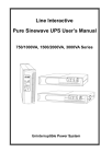
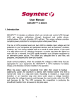
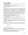
EN Pure Sine Wave Line Interactive UPS PowerWalker VI 1000RT/LE PowerWalker VI 1500RT/LE Manual EN Uninterruptible Power Supply System EN – EN EN SAFETY INSTRUCTION – CAUTION 1 IMPORTANT SAFETY INSTRUCTIONS SAVE THESE INSTRUCTIONS - This manual contains important instructions that should be followed during installation and maintenance of the UPS and batteries. WARNING: Do not attempt to perform repair or service with this UPS. This UPS contains high voltage which could cause electrical shock even when the unit is disconnected from the mains outlet; the dangerous voltage may still be present through the battery. All maintenance and battery replacement should be performed by qualified service personnel only. 1. This UPS should be placed indoors with adequate airflow and free of contamination. To install or operate it in a clean and indoor environment, free from moisture, flammable liquids, and direct sunlight. Ambient temperature range must be 0°C to 40°C (32°F to 104°F). 2. This UPS is designed for Commercial/Industrial use only. It is not intended for use with life support application and other designated “life-critical” devices. 3. Do not remove the input power cord when this UPS is turned on. Remove the safety ground from this UPS and the equipment connected to the UPS. 4. Turn off this UPS and disconnect input power cord before battery replacement. 5. Battery contains high short-circuit current. Replacing or servicing the battery should be performed and supervised by qualified service personnel who are knowledgeable of batteries and requires precautions. Remove watches and jewelries Use tools with insulated handles Wear rubber gloves and boots. Do not lay tools or metal parts on top of batteries. Disconnect charging source prior to connecting or disconnecting battery terminals. 6. When replacing the batteries, use the appropriate replacement battery kits, same number and type of battery are MUST. 7. Do not open or mutilate the battery. Released electrolyte is harmful to skin and eyes that may be toxic. EN – EN 8. Do not dispose of battery in a fire. Battery may explode. Proper disposal of battery is required. Please refer to your local laws and regulations for disposal requirements. 9. This UPS contains high voltages which may cause the risk of electric shock. Do not remove cover. There are no user replaceable parts inside this UPS. Please contact your local dealer or distributor for service. 10. This pluggable type equipment with battery already installed by the supplier is operator installable and may be operated by laymen. 11. During the installation of this equipment it should be assured that the sum of the leakage currents of the UPS and the connected loads does not exceed 3.5mA. 12. Attention, hazardous through electric shock. Also with disconnection of this unit from the mains, hazardous voltage may still be accessible through supply from battery. The battery supply should be therefore disconnected in the plus and minus pole of the battery when maintenance or service work inside the UPS is necessary. 13. The wall outlet must be within 2 meters of the equipment and accessible to the operator. 2 Description of Commonly Used Symbols Sym b ol & Desc rip tio n Sym b ol Desc rip tion Alert you to p a y sp e c ia l a ttention Ca ution of hig h volta g e Alterna ting c urrent sourc e(AC) Direc t c urrent sourc e(DC) Protec tive g round Rec yc le Keep UPS in a c lea r a rea EN 1. INTRODUCTION 1.1 General Introduction This series UPS is pure sine wave line interactive uninterruptible power system with compact design, and it is designed for critical application and environment, such as desktops, servers, workstations, and other networking equipments. The capacity range is available for 1000VA, and 1500VA. This series protects your sensitive electronic equipments against power problems including power sags, spike, brownouts, line noise, and blackouts. This series is powered from the AC mains and supply also AC power backup. Communication and control to the unit is available through serial or USB ports located on the rear panel. The serial port will support communications directly with a server. The communications protocol for the serial ports shall conform to true RS232 interface. This series is designed with outstanding performance and reliability. The unique features include the following: Microprocessor control guarantees high reliability High frequency design Built-in boost and buck AVR User replaceable design for 1000VA /1500VA models Selectable output range and line sensitive Cold startup capability Built-in Dry contact/RS-232/USB communication port Overload, Short-circuit, and overheat protection Rack/Tower 2 in 1 Design for 1000VA/1500VA models Network Transient Protector guards your network communications equipment from surges. EN – EN 1.2 Front Panel The UPS front panel indicates the UPS status and also identifies potential power problems. Figure 1 shows the UPS front panel indicators and controls. 1000VA/1500VA Figure 1. Front Panel Description The UPS has a visible indication about the load level in line mode and the battery capacity in Battery mode. The indicating setting is described in Table 1. EN Table 1. LED Indicator Assignment Line mode The 5th Green Led Lighting. Optional -- (The 1st to 4th green Led lighting to indicate load level) LED1 (green): ≥75% load level. LED2 (green): ≥50% load level. LED3 (green): ≥25% load level. LED4 (green): ≥00% load level. Battery mode The 5th Green Led blinking. Optional – (The 1st to 4th green Led lighting to indicate battery capacity) LED1 (green): battery voltage ≥12.5V / BAT. LED2 (green): battery voltage ≥11.5V / BAT. LED3 (green): battery voltage ≥11.0V / BAT. LED4 (green): battery voltage ≥10.5V / BAT. The sequence of LED, please refer to the front panel below: On/Off Button Mute Button Fault LED LED 1 LED 2 LED 3 LED 4 LED 5 Figure 2. UPS front panel LED If the alarm beeps or a UPS fault indicator stays on, see the tables on page 25 to identify and correct the problem. EN – EN 1.3 UPS Rear Panels This section shows the detailed information about the UPS rear panels 1000VA/1500VA Figure 3. Rear Panel Description EN 2. INSTALLATION 2.1 Inspecting the Equipment If any equipment has been damaged during the shipping process, keep the shipping cartons and packing materials for the carrier or place of purchase and file a claim for shipping damage. If you discover damage after acceptance, file a claim for concealed damage. To file a claim for shipping damage or concealed damage: 1) File with the carrier within 15 days of receipt of the equipment; 2) Send a copy of the damage claim within 15 days to your service representative. ATTENTION Check the battery recharge date on the shipping carton label. If the date has expired and the batteries were never recharged, do not use the UPS. Contact your service representative. 2.2 Installing the UPS The following steps explain how to install the UPS. Figure 4 shows a typical installation only. See “UPS Rear Panels” on page 8 for the rear panel of each model. 1. If you are installing power management software, connect your computer to the USB port or UPS communication port using the supplied cable (see page 16). 2. On 230V models (factory-set default), plug the detachable power cord into the input connector on the UPS rear panel. 3. Plug the UPS power cord into a power outlet. 4. Plug the equipment to be protected into the UPS output receptacles. DO NOT protect laser printers with the UPS because of the exceptionally high power requirements of the heating elements. 5. Press down the button, then the indicator illuminates indicating that power is available from the UPS output receptacles. If the alarm beeps or a UPS fault indicator stays on, see page 25-26. EN – EN 5 Press the button (on the front panel) 1 Connect communication cable from computer to UPS(optional) 4 Connect equipment to UPS 2 & 3 Connect UPS to power Figure 4. Typical UPS Installation 2.3 1000VA/1500VA Setup in Tower or Rack configurations CAUTION The1000VA/1500VA models can be applied to rack configuration (with optional rack mount kits). For 1000VA/1500VA models, please follow the following instructions of Tower Configuration Setup & Rack-Mount Configuration Setup. 1. Tower Configuration Setup There are four pieces of plastic stand components accompanied with 1000VA/1500VA models. Two pieces can be assembled to one complete stand. In tower configuration, use the two stands for stabilizing the UPS when it’s in vertical position. The two UPS stands must be attached to the bottom of the UPS unit. 1) Assemble the two stand components together EN EN – EN 2) Slide down the UPS vertically and put the UPS stands at the bottom of the tower. Then place the UPS into two stands carefully. 2. Rack-Mount Configuration Setup This UPS can be installed into standard 19” rack. It requires the height of 2U from the rack. Use the following procedure to install the UPS into a rack. 1) Align the mounting bearings with screw holes on the side of the UPS.(Mind the orientation of plates, fixing as below) 2) Align the mounting ears with screw holes on the side of the UPS and screw together.(Mind the Left and Right plates, fixing as below) 3) Fix the slide to the rack enclosure with screws 4) Insert UPS into the slide assemblies and lock it well in the rack enclosure EN 3. Tower Configuration to Rack-Mount Configuration 1) Slide up the UPS vertically and put the UPS out of the stands. Place the UPS on flat area with a soft and clean cushion EN – EN 2) Align the mounting bearings with screw holes on the side of the UPS 3) Align the mounting ears with screw holes on the side of the UPS and screw together then Insert UPS into the slide assemblies and lock it in the rack enclosure 4. Rack-Mount Configuration to Tower Configuration 1) Unscrew the UPS from the Rack enclosure 2) Unscrew the ears and the bearings from the UPS 3) Slide down the UPS vertically and put the UPS stands at the end of the tower. Place the UPS into two stands carefully EN 3. OPERATION 3.1 Starting Up After the UPS is connected to a power outlet, the UPS enters Standby mode. To turn on the UPS, press down the button. After the UPS is turned on, it enters Normal mode. The indicator will light indicating that power is available from the UPS output receptacles. 3.2 Starting the UPS on Battery mode NOTE The UPS will not detect the input frequency automatically when starting on battery; the default frequency is set to 50Hz. To turn on the UPS without utility power, press down the button. The UPS will also supply power to the connected equipments and operate in Battery Mode. At the meantime, the indicator will flash and the alarm will sound every 10 seconds. 3.3 Muting the Buzzer Press down the button to initiate the Muting function in Battery mode. If you want to release the muting, press up the button. NOTE The Muting function only can be initiated in Battery mode, and the alarm will continue beeping if there is a UPS fault, low battery condition, or if the battery needs to be replaced. 3.4 Turning the UPS off To turn off the UPS, press and release the button and then unplug the UPS from the power outlet. If you do not unplug the UPS, it remains in Standby mode. 3.5 Standby Mode When the UPS is turned off and remains plugged into a power outlet, the UPS is in Standby mode. All indicators are off and power is not available to your equipment. The battery recharges when necessary. EN – EN 4. ADDITIONAL UPS FEATURES 4.1 Communication Options The UPS is equipped with a USB and a DB-9 communication port. Either the USB port or the DB-9 communication port may be used to monitor the UPS. 1. USB Port The UPS can communicate with a USB-compliant computer using WinPower Monitoring Software. 2. RS232+Dry Contact The RS232 pin functions are described in Table 2. Table 2. DB9 Female pin functions (RS232 +dry contact) PIN # Description I/O 1 Low Battery Output 2 3 4 5 6 7 TxD RxD DTR Common DSR RTS Output Input Input -Output Input 8 AC Fail Output Function Explanation Low Battery Output (*normally open, pull to Pin#5 when battery low alarm in battery mode) TxD RxD (tied to pin 6) Common (tied to chassis) (tied to pin 4) No connection AC Output Fail (*normally open, pull to Pin#5 when UPS is in battery mode). 4.2 Monitoring Software Installation Connected by USB to a PC or notebook, the Software enables communication between the UPS and the computer. The UPS software monitors the status of the UPS, shuts down the system before the UPS is exhausted and can remotely observe the UPS via the Network (enabling users to manage their system more effectively). Upon AC failure or UPS battery low, UPS takes all EN necessary actions without intervention from the system administrator. In addition to automatic file saving and system shut-down functions, it can also send warning messages via pager, e-mail etc. Use the bundled CD and follow the on-screen instructions to install the software WinPower. Enter the following serial No. to install software: 511C1-01220-0100-478DF2A After the software is successfully installed, the communication with UPS has been established and a green icon will appear in the system tray. Double-click the icon to use the monitor software. You can schedule UPS shutdown/start-up and monitor UPS status through PC. Detail instructions please refer to the e-manual in the software. Figure 5. UPS communicates with a computer using WinPower Installation procedure: Check www.powerwalker.com/winpower.html from time to time to get the latest version of monitoring software. EN – EN 4.3 Network Transient Protector The Network Transient Protector is located on the rear panel and has jacks labeled IN and OUT. Please connect the input connector of the equipment you are protecting to the jack labeled OUT, and connect the network cable to the jack labeled IN. 5. BATTERY REPLACEMENT 5.1 1000VA/1500VA models Follow the steps and charts below to replace batteries for 1000/1500VA models: 1. Remove the battery door front panel by pulling on both ends. 2. Unscrew the battery plate from UPS. 3. Disconnect the RED battery cable. EN EN – EN 4. Pull the battery out (from right side) onto flat area. 5. Disconnect the BLACK battery cable. 6. Reconnect the BLACK battery cable to the new batteries. 7. Slide the new batteries into battery case. 8. Reconnect the battery cable and screw up the battery bracket. 9. Close and reinstall the front panel back to battery case 6. SPECIFICATIONS MODEL Capacity Input VA/W PowerWalker VI 1000RT/LE PowerWalker VI 1500RT/LE 1000VA/600W 1500VA/870W Voltage 220/230/240VAC Acceptable 0-300VAC Voltage Range Nominal 50/60Hz ±5Hz for Normal Mode; >40Hz for Generator Mode Frequency Output Voltage 220/230/240VAC Regulation +/-15% (Max) of nominal voltage (Normal Mode) Regulation +/- 5% (Battery Mode) Voltage Waveform Sine wave Frequency 50Hz or 60Hz Overload Normal Mode 110 % ± 8 %,fault after 3 minutes;130% ± 8 %,fault after 10 cycles minimum Capability Boost/Buck Mode 80%+ 8 %/-4%;overload alarming after 25minutes,fault after 30minutes Battery Mode 110 % ± 8 %,fault after 30 seconds;120 % ± 8 %,fault after 5 cycles minimum Transfer Typical 2-7 ms typical, 10ms max. Time Efficiency Normal Mode > 95% (Rated full load, battery full charged) Boost/Buck Mode > 90% (Rated full load, battery full charged) Battery Mode Battery & Configuration Charger Type Backup Time Status Indicators > 80% (Rated full load, battery full charged) 12V,7Ah(2) 12V,9Ah(2) Seals, maintenance-free, valve-regulated, lead acid Recharge Time <6 hours to 90% <8 hours to 90% 100% SPS load 4’00’’ 3’00’’ 80% SPS load 5’30’’ 4’30’’ 50% SPS load 11’00’’ 10’00’’ 100W SPS load 35’00’’ Line mode Battery mode 40’00’’ The 5st Green Led Lighting. The 5st Green Led blinking every 10s. Load level in Line mode: Load/Battery Level ≥75%:LED1~LED4 lighting; ≥50%:LED2~LED4 lighting; ≥25%:LED3~LED4 lighting; ≥00%:LED4 lighting Battery level in Battery mode: ≥12.5V / BAT:LED1~LED4 lighting; ≥11.5V / BAT:LED2~LED4 lighting; ≥11.0V / BAT:LED3~LED4 lighting; ≥10.5V / BAT:LED4 lighting NOTE: The numbers of LEDs please refer to Figure 2. EN Fan Fault (Fault) Output Red LED and LED1 (the first green) Lighting Voltage Red LED and LED2 (the 2nd green) Lighting low (Fault) Output Voltage Red LED and LED3 (the 3rd green) Lighting high (Fault) Output Short Red LED and LED4 (the 4th green) Lighting Circuit (Fault) Overload (Fault) Red LED Lighting and LED5 (green) blinking in Bat mode, lighting in Line mode - Battery replace Audible alarm Red LED Blinking - Over charge Red LED Blinking - Charger fail Red LED Blinking - Back up mode Sounding every 10 seconds - Battery low Sounding every 1 second - Overload Sounding every 0.5 seconds - Over charge Sounding every 1.5 seconds - Over temperature Sounding every 2.5 seconds - Battery replace Sounding every 3 seconds - Charger fail Sounding every 5 seconds - Fault Dimensions Dimensions(L*W* and Weights H mm) Weight(kg) Environment and Safety Operating Temperature Relative Humidity Audible Noise @1 meter Safety Conformance EMC (Class A) Continuous sounding 390*86*328 8.62 10.36 0℃ to +40℃ 0 to 90% Relative Humidity (Non-condensing) <45 dBA EN62040-1-1, CE EN62040-2 C2 EN – EN 7. TROUBLE SHOOTING 7.1 Audible Alarm Trouble Shooting: Problem Cause Sounding every 10 seconds Sounding every 0.5 seconds Sounding every second Sounding every 1.5 seconds Sounding every 2.5 seconds The UPS is on battery Output overload The battery is running low Battery overcharge UPS internal temperature is too high Sounding every 3.0 seconds Battery may need to be charged or service Charger fail Sounding every 5.0 seconds Continuously sounding The UPS fails or fan fault Solution Check the input voltage Check load level indicator and remove some load Save your work and turn off your equipment Save your work and turn off your equipment Shutdown is imminent. Save your work and turn off your equipment. Turn off the UPS. Clear vents and remove any heat sources. Ensure the airflow around the UPS is not restricted. Wait at least 5 minutes and restart the UPS. If the condition persists, contact your service representative Replace the battery Please contact your local dealer Please contact your local dealer 7.2 Visible Alarm Trouble Shooting: The UPS has a visible alarm feature to help you to delete to and put solving some common potential power problems. About the numbering of LEDs, please refer to the Figure. 2 UPS front panel LED on Page 7. Problem Cause Solution Fault LED and LED1 lighting UPS fan fault (1000/1500VA models only) Output overload Check whether there is something blocks the fan. Or, contact your local dealer. Check load level indicator and remove some load Output voltage too low Output voltage too high Output short circuit Please contact your local dealer Fault LED lighting and LED5 lighting or flashing Fault LED and LED2 lighting Fault LED and LED3 lighting Fault LED and LED4 lighting Please contact your local dealer Check the output receptacles, or contact your local dealer EN 7.3 General Trouble Shooting: Problem Cause Solution The UPS is not on when power switch is pressed The power cord is not connected correctly The wall outlet may be faulty UPS output short circuit or overload Check the power cord connection Please contact your local qualified electrician 1. Disconnect all loads and ensure nothing is lodged in output receptacles 2. Ensure loads are not detective or shorted internally Please contact your local dealer Check the output fuse UPS could not provide power to the load Back up time of the battery has been reduced The UPS fault LED is blinking. The UPS fault LED is lighting . Connected equipments lost power while connected to the UPS The UPS is beeping continuously Button does not work Internal fuse may be blown Power is present on one output receptacle No output from any output receptacle Battery is not charged Battery may not be able to hold a full charge due to age. The UPS fails The UPS may be overloaded The UPS may fail 1. 2. Check the connected cable Ensure the load does not exceed the maximum rating of UPS Re-charge the battery at least 24 hours 1. Recharge the battery at least 8 hours 2. Replace Battery Save your work and turn off equipment. Please contact your local dealer Check the load status Please contact your local dealer The UPS is in fault condition Check the audible alarms and visible condition tables 1. 1. 2. The UPS is in green mode Button is Broken 2. Wait for a while and try again Please contact your local dealer EN – EN