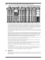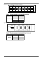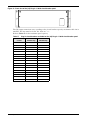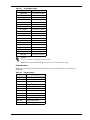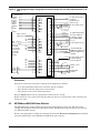
1
DC POWER
Helios DC System 4000/48
1500, 3000, 4000 & 6000 A
DC Power System
User
Manual
TABLE OF CONTENTS
1.0
ABOUT THIS DOCUMENT . . . . . . . . . . . . . . . . . . . . . . . . . . . . . . . . . . . . . . . . . . . . . . . . 1
1.1
Purpose of This Document . . . . . . . . . . . . . . . . . . . . . . . . . . . . . . . . . . . . . . . . . . . . . . . . . . 1
1.2
Applicability of This Document . . . . . . . . . . . . . . . . . . . . . . . . . . . . . . . . . . . . . . . . . . . . . . 1
2.0
INTRODUCTION . . . . . . . . . . . . . . . . . . . . . . . . . . . . . . . . . . . . . . . . . . . . . . . . . . . . . . . 2
2.1
Description . . . . . . . . . . . . . . . . . . . . . . . . . . . . . . . . . . . . . . . . . . . . . . . . . . . . . . . . . . . . . . 2
2.2
Applications . . . . . . . . . . . . . . . . . . . . . . . . . . . . . . . . . . . . . . . . . . . . . . . . . . . . . . . . . . . . . 3
2.3
Control and Distribution Cabinets - Typical Configurations. . . . . . . . . . . . . . . . . . . . . . . 4
3.0
SPECIFICATIONS . . . . . . . . . . . . . . . . . . . . . . . . . . . . . . . . . . . . . . . . . . . . . . . . . . . . . . 6
3.1
Framework . . . . . . . . . . . . . . . . . . . . . . . . . . . . . . . . . . . . . . . . . . . . . . . . . . . . . . . . . . . . . . 6
3.1.1
3.1.2
3.2
Conventional Controller . . . . . . . . . . . . . . . . . . . . . . . . . . . . . . . . . . . . . . . . . . . . . . . . . . . . 7
3.2.1
3.2.2
3.3
Mechanical Specifications of the Conventional Controller . . . . . . . . . . . . . . . . . . . . . . . . . 7
Electrical Specifications of the Conventional Controller . . . . . . . . . . . . . . . . . . . . . . . . . . . 7
Distribution Panels . . . . . . . . . . . . . . . . . . . . . . . . . . . . . . . . . . . . . . . . . . . . . . . . . . . . . . . 8
3.3.1
3.3.2
3.4
Mechanical Specifications of a Cabinet. . . . . . . . . . . . . . . . . . . . . . . . . . . . . . . . . . . . . . . . . 6
Electrical Specifications of the Cabinets. . . . . . . . . . . . . . . . . . . . . . . . . . . . . . . . . . . . . . . . 6
Fuse Panels . . . . . . . . . . . . . . . . . . . . . . . . . . . . . . . . . . . . . . . . . . . . . . . . . . . . . . . . . . . . . . 8
Circuit Breaker Panels . . . . . . . . . . . . . . . . . . . . . . . . . . . . . . . . . . . . . . . . . . . . . . . . . . . . 13
Externally Mounted Battery Return Busbar . . . . . . . . . . . . . . . . . . . . . . . . . . . . . . . . . . 18
3.4.1
3.4.2
Mechanical Specifications of the External Battery Return Busbar . . . . . . . . . . . . . . . . . 18
Electrical Specifications of the External Battery Return Busbar . . . . . . . . . . . . . . . . . . . 18
3.5
Terminating Assemblies (Optional). . . . . . . . . . . . . . . . . . . . . . . . . . . . . . . . . . . . . . . . . . 19
3.6
MPS300 and MPA100 Power Shelves . . . . . . . . . . . . . . . . . . . . . . . . . . . . . . . . . . . . . . . . 20
3.6.1
3.6.2
3.7
Rectifiers . . . . . . . . . . . . . . . . . . . . . . . . . . . . . . . . . . . . . . . . . . . . . . . . . . . . . . . . . . . . . . . 21
3.7.1
3.7.2
3.7.3
3.7.4
3.8
Mechanical Specifications of the MPS300 and MPA100 Power Shelves . . . . . . . . . . . . . 20
Electrical Specifications of the Power Shelves . . . . . . . . . . . . . . . . . . . . . . . . . . . . . . . . . . 21
Helios Rectifier 100/48 . . . . . . . . . . . . . . . . . . . . . . . . . . . . . . . . . . . . . . . . . . . . . . . . . . . . .
Helios Rectifiers 200I/48 and 200E/48 . . . . . . . . . . . . . . . . . . . . . . . . . . . . . . . . . . . . . . . .
Electrical Specifications of the Helios Rectifiers 200I/48 and 200E/48. . . . . . . . . . . . . . .
Standards . . . . . . . . . . . . . . . . . . . . . . . . . . . . . . . . . . . . . . . . . . . . . . . . . . . . . . . . . . . . . . .
21
22
24
24
Helios Monitor 3000/48 (Optional) . . . . . . . . . . . . . . . . . . . . . . . . . . . . . . . . . . . . . . . . . . 25
3.8.1
3.8.2
Mechanical Specifications . . . . . . . . . . . . . . . . . . . . . . . . . . . . . . . . . . . . . . . . . . . . . . . . . . 25
Electrical Specifications. . . . . . . . . . . . . . . . . . . . . . . . . . . . . . . . . . . . . . . . . . . . . . . . . . . . 25
3.9
600 A and 1200 A Battery Disconnect Unit (Optional) . . . . . . . . . . . . . . . . . . . . . . . . . . 25
3.10
AC Junction Box . . . . . . . . . . . . . . . . . . . . . . . . . . . . . . . . . . . . . . . . . . . . . . . . . . . . . . . . . 26
3.10.1 Mechanical Specifications . . . . . . . . . . . . . . . . . . . . . . . . . . . . . . . . . . . . . . . . . . . . . . . . . . 26
3.10.2 Electrical Specifications. . . . . . . . . . . . . . . . . . . . . . . . . . . . . . . . . . . . . . . . . . . . . . . . . . . . 26
i
3.11
Overall Power System Specifications . . . . . . . . . . . . . . . . . . . . . . . . . . . . . . . . . . . . . . . . 26
3.11.1
3.11.2
3.11.3
3.11.4
3.11.5
Standards . . . . . . . . . . . . . . . . . . . . . . . . . . . . . . . . . . . . . . . . . . . . . . . . . . . . . . . . . . . . . . .
Mechanical Specifications of Fully Equipped Power Cabinets . . . . . . . . . . . . . . . . . . . . .
Electrical Specifications . . . . . . . . . . . . . . . . . . . . . . . . . . . . . . . . . . . . . . . . . . . . . . . . . . . .
Environmental Specifications . . . . . . . . . . . . . . . . . . . . . . . . . . . . . . . . . . . . . . . . . . . . . . .
Floor and Point Loading. . . . . . . . . . . . . . . . . . . . . . . . . . . . . . . . . . . . . . . . . . . . . . . . . . . .
26
26
27
27
27
4.0
OPERATION . . . . . . . . . . . . . . . . . . . . . . . . . . . . . . . . . . . . . . . . . . . . . . . . . . . . . . . . 28
4.1
General . . . . . . . . . . . . . . . . . . . . . . . . . . . . . . . . . . . . . . . . . . . . . . . . . . . . . . . . . . . . . . . . 28
4.2
Conventional Controller. . . . . . . . . . . . . . . . . . . . . . . . . . . . . . . . . . . . . . . . . . . . . . . . . . . 28
4.2.1
4.2.2
Front Panel . . . . . . . . . . . . . . . . . . . . . . . . . . . . . . . . . . . . . . . . . . . . . . . . . . . . . . . . . . . . . . 28
Rear Panel. . . . . . . . . . . . . . . . . . . . . . . . . . . . . . . . . . . . . . . . . . . . . . . . . . . . . . . . . . . . . . . 32
4.3
MPS300 and MPA100 Power Shelves . . . . . . . . . . . . . . . . . . . . . . . . . . . . . . . . . . . . . . . . 34
4.4
Rectifiers . . . . . . . . . . . . . . . . . . . . . . . . . . . . . . . . . . . . . . . . . . . . . . . . . . . . . . . . . . . . . . . 35
4.5
AC Junction Box . . . . . . . . . . . . . . . . . . . . . . . . . . . . . . . . . . . . . . . . . . . . . . . . . . . . . . . . . 35
4.6
Distribution Panels . . . . . . . . . . . . . . . . . . . . . . . . . . . . . . . . . . . . . . . . . . . . . . . . . . . . . . 35
4.7
Terminating Assemblies (Optional) . . . . . . . . . . . . . . . . . . . . . . . . . . . . . . . . . . . . . . . . . 35
4.8
Helios Monitor 3000/48 (Optional) . . . . . . . . . . . . . . . . . . . . . . . . . . . . . . . . . . . . . . . . . . 36
4.9
600 A and 1200 Battery Disconnect Units (Optional) . . . . . . . . . . . . . . . . . . . . . . . . . . . 36
5.0
MAINTENANCE . . . . . . . . . . . . . . . . . . . . . . . . . . . . . . . . . . . . . . . . . . . . . . . . . . . . . . 37
5.1
General . . . . . . . . . . . . . . . . . . . . . . . . . . . . . . . . . . . . . . . . . . . . . . . . . . . . . . . . . . . . . . . . 37
5.1.1
5.1.2
Helios Monitor 3000/48 . . . . . . . . . . . . . . . . . . . . . . . . . . . . . . . . . . . . . . . . . . . . . . . . . . . . 37
Controller and Rectifiers . . . . . . . . . . . . . . . . . . . . . . . . . . . . . . . . . . . . . . . . . . . . . . . . . . . 37
5.2
Troubleshooting . . . . . . . . . . . . . . . . . . . . . . . . . . . . . . . . . . . . . . . . . . . . . . . . . . . . . . . . . 39
5.3
Addition / Replacement Procedures. . . . . . . . . . . . . . . . . . . . . . . . . . . . . . . . . . . . . . . . . . 40
5.3.1
5.3.2
5.3.3
5.3.4
5.3.5
Addition or Replacement of a Rectifier . . . . . . . . . . . . . . . . . . . . . . . . . . . . . . . . . . . . . . . .
Replacing a Rectifier . . . . . . . . . . . . . . . . . . . . . . . . . . . . . . . . . . . . . . . . . . . . . . . . . . . . . .
Adding or Replacing a Battery String . . . . . . . . . . . . . . . . . . . . . . . . . . . . . . . . . . . . . . . . .
Replacement of a Distribution Fuse Block or Circuit Breaker . . . . . . . . . . . . . . . . . . . . .
Replacing a Cabinet Alarm Lamp . . . . . . . . . . . . . . . . . . . . . . . . . . . . . . . . . . . . . . . . . . . .
40
45
47
48
48
6.0
REFERENCE DOCUMENTS . . . . . . . . . . . . . . . . . . . . . . . . . . . . . . . . . . . . . . . . . . . . . . 49
7.0
LIST OF TERMS. . . . . . . . . . . . . . . . . . . . . . . . . . . . . . . . . . . . . . . . . . . . . . . . . . . . . . 50
ii
FIGURES
Figure 1
Figure 2
Figure 3
Figure 4
Figure 5
Figure 6
Figure 7
Figure 8
Figure 9
Figure 10
Figure 11
Figure 12
Figure 13
Figure 14
Figure 15
Figure 16
Figure 17
Figure 18
Figure 19
Figure 20
Figure 21
Figure 22
Figure 23
Figure 24
Figure 25
Figure 26
Figure 27
Figure 28
Figure 29
Figure 30
Figure 31
Figure 32
Figure 33
Figure 34
Figure 35
Figure 36
Front view of a typical bottom fed 4000 A Helios DC System 4000/48 power system . . . . . . . 2
Front view of a typical 6000 A Helios DC System 4000/48 power system . . . . . . . . . . . . . . . . 3
Typical configurations for Helios DC System 4000/48 control, distribution and
rectifier cabinets . . . . . . . . . . . . . . . . . . . . . . . . . . . . . . . . . . . . . . . . . . . . . . . . . . . . . . . . . . . . . . 4
Front view of the Conventional Controller . . . . . . . . . . . . . . . . . . . . . . . . . . . . . . . . . . . . . . . . . 7
Front view of the 20 QFF 0-5 A fuse panels . . . . . . . . . . . . . . . . . . . . . . . . . . . . . . . . . . . . . . . . 8
Front view of the (16) QFF 0-5 A & (12) ABS 5-30 A fuse panels . . . . . . . . . . . . . . . . . . . . . . . 9
Front view of the (16) QFF 0-5 A & (6) TPN 5-30 A fuse panels . . . . . . . . . . . . . . . . . . . . . . . . 9
Front view of the (8) TPN 5-30 A fuse panels . . . . . . . . . . . . . . . . . . . . . . . . . . . . . . . . . . . . . . 10
Front view of the (4) RS100P 70-100 A fuse panels . . . . . . . . . . . . . . . . . . . . . . . . . . . . . . . . . 10
Front view of the (4) CRS200P 150-200 A/
(4) CRS200P 150-200 A (w/load shunts) fuse panels . . . . . . . . . . . . . . . . . . . . . . . . . . . . . . . . 11
Front view of the (4) TPL 225-600 A fuse panels . . . . . . . . . . . . . . . . . . . . . . . . . . . . . . . . . . . 11
Front view of the (18) TPS 1-70 A fuse panel . . . . . . . . . . . . . . . . . . . . . . . . . . . . . . . . . . . . . . 12
Front view of the (24) Plug-In 1-100 A circuit breaker panel . . . . . . . . . . . . . . . . . . . . . . . . . 14
Front view of the (4) 70-250 A circuit breaker panel . . . . . . . . . . . . . . . . . . . . . . . . . . . . . . . . 15
Front view of the (2) 400 A circuit breaker panel . . . . . . . . . . . . . . . . . . . . . . . . . . . . . . . . . . . 16
Front view of the (1) 600-700 A circuit breaker panel . . . . . . . . . . . . . . . . . . . . . . . . . . . . . . . 16
Top and side views of the external battery return busbar . . . . . . . . . . . . . . . . . . . . . . . . . . . . 18
Perspective view of the a terminating assemblies . . . . . . . . . . . . . . . . . . . . . . . . . . . . . . . . . . 19
Front view of the MPS300 power shelf (shown empty) . . . . . . . . . . . . . . . . . . . . . . . . . . . . . . 20
Front view of the MPA100 power shelf (shown empty) . . . . . . . . . . . . . . . . . . . . . . . . . . . . . . 21
Front view of the Helios Rectifier 100/48 . . . . . . . . . . . . . . . . . . . . . . . . . . . . . . . . . . . . . . . . . 21
Front view of the Helios Rectifiers 200I/48 and 200E/48 . . . . . . . . . . . . . . . . . . . . . . . . . . . . . 23
Front view of the Helios Monitor 3000/48 (without the mounting brackets) . . . . . . . . . . . . . 25
600 A Battery Disconnect Unit . . . . . . . . . . . . . . . . . . . . . . . . . . . . . . . . . . . . . . . . . . . . . . . . . 25
Front view of the AC junction box (with the front panel open) . . . . . . . . . . . . . . . . . . . . . . . . 26
Front view of the Conventional Controller . . . . . . . . . . . . . . . . . . . . . . . . . . . . . . . . . . . . . . . . 28
Shunt range selection settings. . . . . . . . . . . . . . . . . . . . . . . . . . . . . . . . . . . . . . . . . . . . . . . . . . 30
Equalize voltage and duration settings. . . . . . . . . . . . . . . . . . . . . . . . . . . . . . . . . . . . . . . . . . . 31
Terminal blocks and connectors layout at the rear of the Conventional Controller. . . . . . . . 32
Wiring diagram and pin assignment of terminal blocks TB1 to TB4 . . . . . . . . . . . . . . . . . . . 33
Wiring diagram and pin assignment of terminal blocks TB5 and TB6, and
connectors P1 to P26. . . . . . . . . . . . . . . . . . . . . . . . . . . . . . . . . . . . . . . . . . . . . . . . . . . . . . . . . . 34
AC connections in a Helios Rectifier 200E/48 . . . . . . . . . . . . . . . . . . . . . . . . . . . . . . . . . . . . . . 42
AC connections in the female receptacle for a Helios Rectifier 200I/48 or
a Helios Rectifier 200E/48 . . . . . . . . . . . . . . . . . . . . . . . . . . . . . . . . . . . . . . . . . . . . . . . . . . . . . 43
AC connections inside the junction box (top fed shown) for a Helios Rectifier 200E/48. . . . . 43
AC cable routing for the Helios Rectifiers 200E/48 in a top fed system . . . . . . . . . . . . . . . . . 44
AC cable routing for the Helios Rectifiers 200E/48 in a bottom fed system . . . . . . . . . . . . . . 44
iii
TABLES
Table 1
Table 2
Table 3
Table 4
Table 5
Table 6
Table 7
Table 8
Table 9
Table 10
Table 11
Table 12
Table 13
Table 14
Table 15
Table 16
Table 17
Table 18
Table 19
Table 20
Table 21
Table 22
Table 23
Table 24
Table 25
Table 26
Table 27
Table 28
Table 29
Table 30
Table 31
Table 32
Table 33
Table 34
Table 35
Table 36
Table 37
Table 38
Table 39
iv
Rectifier cabinets. . . . . . . . . . . . . . . . . . . . . . . . . . . . . . . . . . . . . . . . . . . . . . . . . . . . . . . . . . . . . . 5
Control and distribution cabinets . . . . . . . . . . . . . . . . . . . . . . . . . . . . . . . . . . . . . . . . . . . . . . . . 5
Auxiliary distribution cabinets . . . . . . . . . . . . . . . . . . . . . . . . . . . . . . . . . . . . . . . . . . . . . . . . . . 5
Mechanical specifications of the cabinet (empty) . . . . . . . . . . . . . . . . . . . . . . . . . . . . . . . . . . . . 6
Mechanical specifications of the Conventional Controller . . . . . . . . . . . . . . . . . . . . . . . . . . . . . 7
Mechanical specifications of the fuse panels . . . . . . . . . . . . . . . . . . . . . . . . . . . . . . . . . . . . . . . . 8
Fuse sizes available for the (20) QFF 0-5 A fuse panels . . . . . . . . . . . . . . . . . . . . . . . . . . . . . . . 8
Fuse sizes available for the (16) QFF 0-5 A & (12) ABS 5-30 A fuse panels . . . . . . . . . . . . . . . 9
Fuse sizes available for the (16) QFF 0-5 A & (6) TPN 5-30 A fuse panels . . . . . . . . . . . . . . . . 9
Fuse sizes available for the (8) TPN 5-30 A fuse panels. . . . . . . . . . . . . . . . . . . . . . . . . . . . . . 10
Fuse sizes available for the (4) RS100P 70-100 A fuse panels . . . . . . . . . . . . . . . . . . . . . . . . . 10
Fuse sizes available for the (4) CRS200P 150-200 A/
(4) CRS200P 150-200 A (w/load shunts) fuse panels . . . . . . . . . . . . . . . . . . . . . . . . . . . . . . . . 11
Fuse sizes available for the (4) TPL 225-600 A fuse panels . . . . . . . . . . . . . . . . . . . . . . . . . . . 11
Fuse sizes available for the (18) TPS 1-70 A fuse panel . . . . . . . . . . . . . . . . . . . . . . . . . . . . . . 12
Electrical specifications of the fuse panels . . . . . . . . . . . . . . . . . . . . . . . . . . . . . . . . . . . . . . . . 13
Mechanical specifications of the circuit breaker panels . . . . . . . . . . . . . . . . . . . . . . . . . . . . . . 13
Plug-in circuit breakers available for the (24) Plug-In 1-100 A circuit breaker panel . . . . . . 14
Circuit breaker sizes available for the (4) 70-250 A circuit breaker panel . . . . . . . . . . . . . . . 15
Circuit breaker kits available for the (2) 400 A circuit breaker panel. . . . . . . . . . . . . . . . . . . 16
Circuit breaker kits available for the (1) 600-700 A circuit breaker panel . . . . . . . . . . . . . . . 16
Electrical specifications of the circuit breaker panels . . . . . . . . . . . . . . . . . . . . . . . . . . . . . . . 17
Mechanical specifications of a single lamination . . . . . . . . . . . . . . . . . . . . . . . . . . . . . . . . . . . 18
Mechanical specifications of the MPS300 and MPA100 power shelves . . . . . . . . . . . . . . . . . . 20
Mechanical specifications of the Helios Rectifier 100/48 . . . . . . . . . . . . . . . . . . . . . . . . . . . . . 21
Electrical specifications of the Helios Rectifier 100/48 . . . . . . . . . . . . . . . . . . . . . . . . . . . . . . . 22
Mechanical specifications of the Helios Rectifiers 200I/48 and 200E/48 . . . . . . . . . . . . . . . . . 22
Electrical specifications of the Helios Rectifiers 200I/48 and 200E/48 . . . . . . . . . . . . . . . . . . 24
Mechanical specifications of the Helios Monitor 3000/48 . . . . . . . . . . . . . . . . . . . . . . . . . . . . . 25
Mechanical specifications of the AC junction box . . . . . . . . . . . . . . . . . . . . . . . . . . . . . . . . . . . 26
Mechanical specifications of fully equipped power cabinets. . . . . . . . . . . . . . . . . . . . . . . . . . . 26
Floor and point loading. . . . . . . . . . . . . . . . . . . . . . . . . . . . . . . . . . . . . . . . . . . . . . . . . . . . . . . . 27
Visual indicators . . . . . . . . . . . . . . . . . . . . . . . . . . . . . . . . . . . . . . . . . . . . . . . . . . . . . . . . . . . . . 28
Transmitted alarms . . . . . . . . . . . . . . . . . . . . . . . . . . . . . . . . . . . . . . . . . . . . . . . . . . . . . . . . . . 29
Potentiometers . . . . . . . . . . . . . . . . . . . . . . . . . . . . . . . . . . . . . . . . . . . . . . . . . . . . . . . . . . . . . . 29
Switches. . . . . . . . . . . . . . . . . . . . . . . . . . . . . . . . . . . . . . . . . . . . . . . . . . . . . . . . . . . . . . . . . . . . 30
DIP switch modules . . . . . . . . . . . . . . . . . . . . . . . . . . . . . . . . . . . . . . . . . . . . . . . . . . . . . . . . . . 30
Fuse . . . . . . . . . . . . . . . . . . . . . . . . . . . . . . . . . . . . . . . . . . . . . . . . . . . . . . . . . . . . . . . . . . . . . . . 31
Test points . . . . . . . . . . . . . . . . . . . . . . . . . . . . . . . . . . . . . . . . . . . . . . . . . . . . . . . . . . . . . . . . . . 31
Fault diagnosis . . . . . . . . . . . . . . . . . . . . . . . . . . . . . . . . . . . . . . . . . . . . . . . . . . . . . . . . . . . . . . 39
1.0
ABOUT THIS DOCUMENT
1.1
Purpose of This Document
This document provides all the necessary information to operate and maintain a Helios DC System 4000/48 power system.
The installation procedures for the Helios DC System 4000/48 power system are covered in installation manual SL-60034.
1.2
Applicability of This Document
This document applies to Helios DC System 4000/48 power systems having any configuration of
equipment.
About This Document
1
2.0
INTRODUCTION
2.1
Description
The Helios DC System 4000/48 is a positive ground, -48 V DC nominal power system consisting of
one control and distribution cabinet and one or more rectifier cabinets. It is available in capacities
of 1500, 3000, 4000 and 6000 A. Auxiliary distribution cabinets can be added as required for additional distribution. Remote monitoring, temperature compensation and battery disconnect
options are also available. The 1500, 3000 and 4000 A versions use internal -48 V bussing and
external BR+ bussing, while the 6000 A version uses overhead bussing. Figure 1 shows a typical
bottom fed 4000 A system, while Figure 2 shows a typical 6000 A system.
Figure 1
Front view of a typical bottom fed 4000 A Helios DC System 4000/48 power system
1200 A rectifier cabinets
2
Introduction
Main cabinet Aux dist. cabinet
Figure 2
Front view of a typical 6000 A Helios DC System 4000/48 power system
Aux dist. cabinets
Main cabinet
1200 A rectifier cabinets
Cables are used for inter-cabinet connections (1500, 3000 and 6000 A systems) or connections to
the overhead busbars (6000 A system) for ease of expansion on live systems. In a 1500, 3000 or
4000 A systems, the power system battery return (BR) busbar is mounted externally from the cabinet to facilitate the connections of the battery return cables. In a 6000 A system, a separate BR
busbar dedicated to the battery returns for the loads is mounted externally from the overhead
busbar duct to facilitate the connections of the load battery return cables.
The Helios DC System 4000/48 provides a variety of monitoring and alarm features, such as high/
low float and high/low voltage alarm, high voltage shutdown, fuse and breaker alarm and rectifier
failure alarms.
The Helios DC System 4000/48 uses Helios Rectifiers 200I/48, Helios Rectifiers 200E/48 or Helios
Rectifiers 100/48 connected in parallel as building blocks to reach the maximum capacities. The
Helios Rectifiers 200I/48 operate from a 380 V to 415 V three phase, 50 or 60 Hz AC source. The
Helios Rectifiers 200I/48 operate from a 480 V three phase, 50 or 60 Hz AC source. The Helios
Rectifiers 100/operate from a 208 V to 240 V single phase, 50 or 60 Hz AC source.
The 1200 A rectifier cabinet accepts up to six Helios Rectifiers 200I/48 or 200E/48, while the 1000
A rectifier cabinet accepts up to 10 Helios Rectifiers 100/48.
The control and distribution cabinet and the auxiliary distribution cabinets are available with
distribution busbar risers of 2000 A or 3000 A capacity.
The cabinets are seismic qualified to zone 4 (Bellcore) when anchored to a concrete floor whose
compressive strength is at least 2.11 kg/mm2 (3000 psi) and when equipped with a seismic kit.
The cabinets are seismic qualified to zone 2 without the seismic kit.
The cabinets are equipped with a ventilated, lockable door, a ventilated top cover and two rear
ventilated panels.
In many applications, such as with DMS, a consistent single-point ground (SPG) topology must be
maintained for all associated equipment. The Helios DC System 4000/48 complies with this
requirements for single-point grounding (the isolation kit is required).
2.2
Applications
The Helios DC System 4000/48 is designed to operate with DMS systems or any other telecommunication systems whose input is nominal -48 V DC and whose current requirements do not exceed
6000 A capacity.
Introduction
3
2.3
Control and Distribution Cabinets - Typical Configurations
Figure 3 shows the front and side views of typical rectifier and distribution cabinets for a Helios
DC System 4000/48 (bottom cabled cabinets are illustrated - top cabled versions are available).
Figure 3
Typical configurations for Helios DC System 4000/48 control, distribution and rectifier
cabinets
Control and Distribution cabinet
4
Introduction
1200A Rectifier cabinet
Cabinets are available in a variety of configurations as listed in the following tables. Note that for
a 6000 A system, the cabling is always at the top.
Table 1
Rectifier cabinets
Rectifier
Cabinet Capacity
Type
Qty
Cabled top or bottom
1200 A
Helios Rectifier 200I
6
Top
1200 A
Helios Rectifier 200I
6
Bottom
1000 A
Helios Rectifier 100/48
10
Top or bottom
Table 2
1200 A
Helios Rectifier 200E
6
Top
1200 A
Helios Rectifier 200E
6
Bottom
1200 A
Helios Rectifier 200E
6
Top
1200 A
Helios Rectifier 200E
6
Bottom
Control and distribution cabinets
Nominal cabinet capacity
Shunt capacity
Riser busbar capacity
Cabled top or bottom
1500 A
2500 A
2000 A
Top
3000 A
4000 A
3000 A
Top
4000 A
5000 A
3000 A
Top
1500 A
2500 A
2000 A
Bottom
3000 A
4000 A
3000 A
Bottom
4000 A
5000 A
3000 A
Bottom
For a 6000 A system, the charge busbars and the shunt are mounted externally from the control and distribution cabinet.
Table 3
Auxiliary distribution cabinets
Nominal cabinet capacity
Top busbar capacity
Riser busbar capacity
Cabled top or bottom
2000 A
3000 A
2000 A
Top
2000 A
3000 A
2000 A
Bottom
3000 A
4000 A
3000 A
Top
3000 A
4000 A
3000 A
Bottom
Introduction
5
3.0
SPECIFICATIONS
3.1
Framework
The Helios DC System 4000/48 uses cabinet type frameworks. The same cabinet design is used for
the main control and distribution cabinet, the auxiliary distribution cabinets and the rectifier cabinets. The cabinet is always equipped with a front door and door frame (lockable, equipped with
ground straps, and easily removable for installation or maintenance access), a ventilated top
cover made of non-flammable plastic, and two ventilated rear cover panels (equipped with ground
strap and easily removable for installation and maintenance access). Bussing and equipment
(controller, rectifiers, distribution panels, etc.) are added as required, depending on the use of the
cabinet. Seismic bracing is also available as options.
When using the Cable Trough, overhead cabling cannot enter from the front or rear of the system.
It must be confined to the system foot print and enter at the ends of the lineup.
The cabinets may be either top or bottom cabled as determined by the location of the bussing.
3.1.1
Mechanical Specifications of a Cabinet
The mechanical specifications of an empty cabinet are listed in Table 4.
Table 4
Mechanical specifications of the cabinet (empty)
Framework type
Height
Depth
Width
Weight
Cabinet
2134 mm
(84.0 in.)
600 mm
(23.6 in.)
600 mm
(23.6 in.)
114 kg
(251 lb)
Refer to Figure 3 for typical views of cabinets.
3.1.2
Electrical Specifications of the Cabinets
The electrical specifications of equipped cabinets are as follows:
• The main control and distribution cabinet for a 1500 A system has a 2000 A busbar riser and
a common equipment panel e/w one 1500 A CHG and DISCH busbar and a 2500 A system
shunt.
• The main control and distribution cabinet for a 3000A system has a 3000 A busbar riser and a
common equipment panel e/w two 1500 A CHG and DISCH busbars and a 4000 A system
shunt.
• The main control and distribution cabinet for a 4000A system has a 3000 A busbar riser and a
common equipment panel e/w three 1500 A CHG and DISCH busbars and a 5000 A system
shunt.
• A 6000 A system has a 3000 A busbar riser in the main control and distribution cabinet (the
CHG and DISCH busbar and the shunt are external).
• The auxiliary distribution cabinet is available with a 2000 or 3000 A busbar riser.
• A 1200 A rectifier cabinet has 1500 A busbar risers for the DC output of the rectifiers.
6
Specifications
3.2
Conventional Controller
3.2.1
Mechanical Specifications of the Conventional Controller
The mechanical specifications of the Conventional Controller are listed in Table 5.
Table 5
Figure 4
3.2.2
Mechanical specifications of the Conventional Controller
Figure
Height
Depth
Width
Weight
Figure 4
152 mm
(6.0 in.)
76 mm
(3.0 in.)
584 mm
(23 in.)
4.5 kg
(10 lb)
Front view of the Conventional Controller
Electrical Specifications of the Conventional Controller
The operating voltage is -48 V DC. Refer to the 4.0 - Operation and the appropriate user manual
listed in 6.0 - Reference Documents for a detailed list of specifications, operating parameters
and features of the Conventional Controller.
Specifications
7
3.3
Distribution Panels
3.3.1
Fuse Panels
Mechanical specifications of the fuse panels
The mechanical specifications of the fuse panels are listed in Table 6 below.
Table 6
Mechanical specifications of the fuse panels
Panel description
Figure
Height
Width
Weight
(20) QFF 0-5 A
60 A max
Figure 5
76.2 mm
(3.0 in.)
584 mm
(23.0 in.)
3 kg
(6.6 lb)
(16) QFF 0-5 A &
(12) ABS 5-30 A
300 A max
Figure 6
76.2 mm
(3.0 in.)
584 mm
(23.0 in.)
5 kg
(11.0 lb)
(16) QFF 0-5 A &
(6) TPN 5-30 A
250 A max
Figure 7
152.4 mm
(6.0 in.)
584 mm
(23.0 in.)
7 kg
(15.4 lb)
(8) TPN 5-30 A
250 A max
Figure 8
152.4 mm
(6.0 in.)
584 mm
(23.0 in.)
7 kg
(15.4 lb)
(4) RS100P 70-100 A
300 A max
Figure 9
152.4 mm
(6.0 in.)
584 mm
(23.0 in.)
8 kg
(17.8 lb)
(4) CRS200P 150-200 A
600 A max
Figure 10
228.6 mm
(9.0 in.)
584 mm
(23.0 in.)
22 kg
(48.4 lb)
(4) CRS200P 150-200 A
(w/load shunts)
600 A max
Figure 10
228.6 mm
(9.0 in.)
584 mm
(23.0 in.)
24 kg
(52.9 lb)
(4) TPL 225-600 A
1600 A max
Figure 11
304.8 mm
(12.0 in.)
584 mm
(23.0 in.)
32 kg
(70.4 lb)
(18) TPS 1-70 A
600 A max
Figure 12
178 mm
(7.0 in.)
584 mm
(23.0 in.)
35 kg
(77.0 lb)
Note 1: An alarm circuit pack with an alarm indication LED is standard on all panels
Note 2: (4) CRS200P 150-200 A (w/load shunts) is equipped with four shunts.
Figure 5
Front view of the 20 QFF 0-5 A fuse panels
FA
The DC output connections are wire wrap or solder.
Table 7
8
Fuse sizes available for the (20) QFF 0-5 A fuse panels
Fuse type
Current (A)
CPC
QFF1A
1.333
A0205202
QFF1B
2
A0205203
QFF1C
3
A0205204
QFF1D
5
A0205205
QFF1E
0.18
A0205206
QFF1F
0.25
A0205207
QFF1G
0.5
A0205208
QFF1H
0.75
A0205209
QFF3A
DUMMY
A0205210
Specifications
Figure 6
Front view of the (16) QFF 0-5 A & (12) ABS 5-30 A fuse panels
FA
-48 V
The DC output connections are No. 8-32 studs equipped with two hex nuts.
Table 8
Fuse sizes available for the (16) QFF 0-5 A & (12) ABS 5-30 A fuse panels
Fuse type
Current (A)
CPC
5
A0327000
8
A0111415
10
A0315462
12
A0267003
15
A0344157
20
A0314873
25
A0243206
30
A0328460
QFF1A
1.333
A0205202
QFF1B
2
A0205203
QFF1C
3
A0205204
QFF1D
5
A0205205
QFF1E
0.18
A0205206
QFF1F
0.25
A0205207
QFF1G
0.5
A0205208
QFF1H
0.75
A0205209
QFF3A
DUMMY
A0205210
4AB (ABS)
Figure 7
Front view of the (16) QFF 0-5 A & (6) TPN 5-30 A fuse panels
FA
ALM
-48 V
1/2 A
The DC output connections are 0.250-20 studs equipped with two hex nuts.
Table 9
Fuse sizes available for the (16) QFF 0-5 A & (6) TPN 5-30 A fuse panels
Fuse type
DC power (TPN)
Current (A)
CPC
1
A0380108
3
A0380109
6
A0380111
10
A0380112
15
A0380113
20
A0380147
25
A0380148
30
A0380149
Specifications
9
Figure 8
Front view of the (8) TPN 5-30 A fuse panels
FA
ALM
-48 V
1/2 A
The DC output connections are 0.250-20 studs equipped with two hex nuts.
Table 10
Fuse sizes available for the (8) TPN 5-30 A fuse panels
Fuse type
DC power (TPN)
Figure 9
Current (A)
CPC
35
A0380150
40
A0380151
45
A0380152
50
A0380114
60
A0380115
Front view of the (4) RS100P 70-100 A fuse panels
ALM
FA
(1) (2) (3) (4)
(1)
(2)
(3)
(4)
-48 V
The DC output connections are 0.375-16 studs equipped with two hex nuts.
Table 11
Fuse sizes available for the (4) RS100P 70-100 A fuse panels
Fuse type
HRC1-K
10
Specifications
Current (A)
CPC
70
A0722046
80
A0722045
90
A0722044
100
A0722049
Figure 10 Front view of the (4) CRS200P 150-200 A/(4) CRS200P 150-200 A (w/load shunts) fuse panels
(2)
(1)
(1)
(3)
(4)
(3)
FA
ALM
ALM
(4)
(2)
The DC output connections are 0.50-13 studs equipped with two hex nuts.
Table 12
Fuse sizes available for the (4) CRS200P 150-200 A/(4) CRS200P 150-200 A (w/load
shunts) fuse panels
Fuse type
HRC1-J
Current (A)
CPC
110
A0329697
125
A0329696
150
A0722041
175
A0722038
200
A0614832
Figure 11 Front view of the (4) TPL 225-600 A fuse panels
-48 V
(2)
(1)
(1)
(3)
(4)
(3)
FA
ALM
ALM
(2)
(4)
The DC output connections are busbar angles that can accept 535MCM or 750MCM cables, or the
metric equivalent. The lugs must be for two 1/2” dia. bolts at 1-3/4” c-c.
Table 13
Fuse sizes available for the (4) TPL 225-600 A fuse panels
Fuse type
DC power (TPL)
Current (A)
CPC
225
A0380138
300
A0380140
400
A0380141
500
A0380142
600
A0380143
Specifications
11
Figure 12 Front view of the (18) TPS 1-70 A fuse panel
MAX FUSE 70A
1
2
3
4
5
6
7
8
9
10
11
12
13
14
15
16
17
18
FA
UNIT
AMPS
LOAD
FUSE PANEL
600 A MAX PANEL CAPACITY
NT6C21XX
Can accept maximum 1/0 AWG cables and requires one-hole lugs for 1/4” diameter studs.
Table 14
Fuse sizes available for the (18) TPS 1-70 A fuse panel
Fuse type
DC power (TPS)
12
Specifications
Current (A)
CPC
1
A0601322
3
A0601323
5
A0601325
6
A0601326
10
A0601327
15
A0601328
25
A0601330
30
A0601331
40
A0601332
50
A0601333
60
A0601334
70
A0601335
Electrical specifications of the fuse panels
The electrical specifications of the fuse panels are described in Table 15.
Table 15
Electrical specifications of the fuse panels
Fuses
Panel number
Figure
Quantity
Capacity
Busbar
capacity
(20) QFF 0-5 A
60 A max
Figure 5
20
0-5 A
60 A
(16) QFF 0-5 A &
(12) ABS 5-30 A
300 A max
Figure 6
16
12
0-5 A
0-30 A
300 A
(16) QFF 0-5 A &
(6) TPN 5-30 A
250 A max
Figure 7
8
0-30 A
250 A
(8) TPN 5-30 A
250 A max
Figure 8
8
31-60 A
300 A
(4) RS100P 70-100 A
300 A max
Figure 9
4
70-100 A
300 A
(4) CRS200P 150-200 A
600 A max
Figure 10
4
101-200 A
600 A
(4) TPL 225-600 A
1600 A max
Figure 11
4
225-600 A
1600 A
(18) TPS 1-70 A
600 A max
Figure 12
18
0-70 A
600 A
(4) CRS200P 150-200 A (w/load shunts)
600 A max
3.3.2
Circuit Breaker Panels
Mechanical specifications of the circuit breaker panels
The mechanical specifications of the circuit breaker panels are described in Table 16.
Table 16
Mechanical specifications of the circuit breaker panels
Panel description
Figure
Height
Width
Weight
(24) Plug-In 1-100 A
900 A max
Figure 13
165 mm
(6.5 in.)
584 mm
(23.0 in.)
9.1kg
(20 lb.)
(4) 70-250 A
900 A max *
Figure 14
178 mm
(7.0 in.)
584 mm
(23.0 in.)
10.5 kg
(25 lb)
(2) 400 A
Figure 15
178 mm
(7.0 in.)
584 mm
(23.0 in.)
10.5 kg
(25 lb)
(1) 600-700 A
Figure 16
178 mm
(7.0 in.)
584 mm
(23.0 in.)
10.5 kg
(25 lb)
* The 250 A circuit breaker has two poles, thus the panel can accommodate a maximum of two 250 A breakers.
An alarm circuit pack with an alarm indication LED is standard on all panels.
Specifications
13
Figure 13 Front view of the (24) Plug-In 1-100 A circuit breaker panel
The DC output connections vary according to the circuit breaker capacity: maximum cable size is
2/0AWG. The lugs must be for 3/8” dia. bolts at 1” c-c.
Refer to Table 21 for the maximum panel capacity.
Table 17
14
Plug-in circuit breakers available for the (24) Plug-In 1-100 A circuit breaker panel
Nominal
current
CPC Std Trip
CPC Mid Trip
1A
A0723076
A0722751
5A
A0723033
A0722752
10 A
A0723035
A0722754
15 A
A0723037
A0722755
20 A
A0723007
A0722695
25 A
A0723039
A0722707
30 A
A0723040
A0722715
35 A
A0723041
A0722717
40 A
A0723042
A0722721
45 A
A0723069
A0722722
50 A
A0723008
A0722726
60 A
A0723070
A0722727
65 A
A0723071
A0722497
70 A
A0723072
A0722732
80 A
A0723074
A0722733
90 A
A0723077
A0722750
100 A
A0723009
A0722496
Specifications
Figure 14 Front view of the (4) 70-250 A circuit breaker panel
900A MAX. PANEL CAPACITY
CIRCUIT BREAKER PANEL
NT6C12EEA
(4) 70-250
1
FA
REL
(
)
SER NO (
)
2
UNIT
AMPS
1
225
2
225
3
225
4
225
LOAD
3
4
The DC output connections can accommodate two 4/0 cables back to back for each circuit breaker.
The required lugs can be either for two 3/8” holes at 1” c-c or for two 1/2” holes at 1-3/4” c-c.
Refer to Table 21 for the maximum panel capacity.
Table 18
Circuit breaker sizes available for the (4) 70-250 A circuit breaker panel
Nominal current
CPC
70 A (no shunt)
A0617079
70 A (with shunt)
A0617080
70 A (with relay trip)
A0617081
100 A (no shunt)
A0616667
100 A (with shunt)
A0616668
100 A (with relay trip)
A0616669
150 A (no shunt)
A0616670
150 A (with shunt)
A0616671
150 A (with relay trip)
A0616672
200 A (no shunt)
A0616673
200 A (with shunt)
A0616674
200 A (with relay trip)
A0616675
225 A (no shunt)
A0605489
225 A (with shunt)
A0605490
225 A (with relay trip)
A0605492
250 A (no shunt)
A0616676
250 A (with shunt)
A0616677
250 A (with relay trip)
A0616678
The (4) 70-250 A circuit breaker panel can accept up to:
• four breakers (70 to 225 A) mid trip with or without the metering shunt option (1 pole breakers)
• two breakers (70 to 225 A) mid trip with the relay trip option (takes a 2 pole space)
• two breakers (250 A) mid trip with or without the metering shunt option (takes a two pole
breaker)
• one (250 A) breaker mid trip with the relay trip option (takes a 3 pole space)
Specifications
15
Figure 15 Front view of the (2) 400 A circuit breaker panel
900A MAX. PANEL CAPACITY
CIRCUIT BREAKER PANEL
NT6C12EF
(2) 400 A
FA
1
REL
(
)
SER NO (
)
UNIT
AMPS
2
400
1
400
LOAD
2
The DC output connections can accommodate two 750 MCM cables back to back for each circuit
breaker. The required lugs must be for two 1/2” holes at 1-3/4” c-c.
Refer to Table 21 for the maximum panel capacity.
Table 19
Circuit breaker kits available for the (2) 400 A circuit breaker panel
Nominal current
CPC
400 A (no shunt)
P0748316
400 A (with shunt)
P0748317
2 x 400 A (no shunt)
P0748318
2 x 400 A (with shunt)
P0748319
400 A (with relay trip)
P0748320
The panel accepts up to:
• two breakers (400 A) mid trip with or without the metering shunt option
• one breaker (400 A) mid trip with the relay trip option (takes a 3 pole space)
Figure 16 Front view of the (1) 600-700 A circuit breaker panel
900A MAX. PANEL CAPACITY
CIRCUIT BREAKER PANEL
NT6C12EG
(1) 600-700 A
FA
1
REL
(
)
SER NO (
)
UNIT
AMPS
1
600
LOAD
2
The DC output connections can accommodate four 750 MCM cables back to back. The lugs must
be for two 1/2” bolts at 1-3/4” c-c.
Refer to Table 21 for the available circuit breakers and the maximum panel capacity.
Table 20
Circuit breaker kits available for the (1) 600-700 A circuit breaker panel
Nominal current
16
CPC
600 A (no shunt)
P0875700
600 A (e/w shunt)
P0875701
600 A (e/w relay trip)
P0875702
Specifications
Electrical specifications of the circuit breaker panels
The electrical specifications of the circuit breaker panels are described in Table 21.
Table 21
Electrical specifications of the circuit breaker panels
Circuit breakers
Panel description
Figure
Max. Quantity
Capacity
Busbar
capacity
(24) Plug-In 1-100 A
900 A max
Figure 13
24
1-100 A
900A
(4) 70-250 A
900 A max
Figure 14
4
70-250 A
900 A
(2) 400 A
Figure 15
2
400 A
900 A
(1) 600-700 A
Figure 16
1
600 A
900 A
Specifications
17
3.4
Externally Mounted Battery Return Busbar
The battery return busbar is designed to mount on the overhead racking for 6000 A systems and
top cabled 1500, 3000 or 4000 A power systems. It can also be mounted on a wall or on the floor
below the raised floor for bottom cabled 1500, 3000 or 4000 A power systems (which are assumed
to be installed on a raised, computer type floor).
3.4.1
Mechanical Specifications of the External Battery Return Busbar
The external battery return busbar kit consists of a group of single busbar laminations and
attachment hardware assembled as shown in Figure 17 (6000 A shown). The kit can grow vertically in such a way as to maintain the 3-ft maximum radius grounding requirement. Laminations
are added as required to increase the capacity. The mechanical specifications of a single lamination are listed in Table 22.
Table 22
Mechanical specifications of a single lamination
Figure
Length
Width
Thickness
Figure 17
863.6 mm
(34 inches)
152.4 mm
(6 inches)
12.7 mm
(0.5 inches)
Figure 17 Top and side views of the external battery return busbar
6” (152 mm)
Top view of the external ground bar
Future growth as required
Available
configurations:
= 1500* &
3000 A
34” (864 mm)
= 4000 A
Smaller busbar for
small wires and cables
6”
= 6000 A
Side view of the external ground bar installed on
auxiliary framing above the power system
NOTE
All bars and details are 0.5 in. thick.
* For a 1500 A system, only the bottom level is provided for the external
battery return ground bar.
3.4.2
Electrical Specifications of the External Battery Return Busbar
A single busbar lamination has a current carrying capacity of 3000 A.
18
Specifications
3.5
Terminating Assemblies (Optional)
The optional terminating assembly allows top access connections for up to six loads. Refer to
Figure 18. Each load position is rated at 600 A and can accept up to three lugs having 1” or 1-3/4”
c-c hole spacing, for cables up to 777 kcmil.
The terminating assembly is bolted to the top of the main or auxiliary distribution cabinets and,
therefore, increase the cabinet height by 12 inches. The weight of the terminating assembly is
12.5 kg (27.6 lb).
An optional Lexan™ protective cover is available to protect the connections of the load cables.
Figure 18 Perspective view of the a terminating assemblies
Optional
protective
cover
Glastic
insulating
material
NT6C2625
(for main distribution cabinet)
NT6C2624
(for auxiliary distribution cabinet)
Specifications
19
3.6
MPS300 and MPA100 Power Shelves
The MPS300 and MPA100 power shelves are required for the Helios Rectifier 100/48, which is a
plug-in type rectifier. The MPA100 power shelf supports one Helios Rectifier 100/48, while the
MPS300 shelf can support up to three Helios Rectifiers 100/48.
3.6.1
Mechanical Specifications of the MPS300 and MPA100 Power Shelves
The mechanical specifications of the power shelves are listed in Table 23.
Table 23
Mechanical specifications of the MPS300 and MPA100 power shelves
Shelf model
Figure
Height
Depth
Width
Weight
MPS300
Figure 19
533 mm
(21.00 in.)
381 mm
(15.00 in.)
584 mm
(23.00 in.)
16.6 kg
(36.5 lb)
MPA100
Figure 20
178 mm
(7.00 in)
381 mm
(15.00 in.)
584 mm
(23.00 in.)
5.4 kg
(12 lb)
Figure 19 Front view of the MPS300 power shelf (shown empty)
20
Specifications
Figure 20 Front view of the MPA100 power shelf (shown empty)
3.6.2
Electrical Specifications of the Power Shelves
Each rectifier position provides interconnection points for AC input (208 to 240 V nominal), DC
output (-48 V nominal) and control and alarm signals.
3.7
Rectifiers
The Helios system 4000/48 can be equipped with Helios Rectifiers 100/48 for single phase 208/240
V AC operation, with Helios Rectifiers 200I/48 for three phase 380/415 V AC operation, or with
Helios Rectifiers 200E/48 for three phase 480 V AC operation.
3.7.1
Helios Rectifier 100/48
Mechanical specifications of the Helios Rectifier 100/48
The mechanical specifications of the Helios Rectifier 100/48 are listed in Table 24.
Table 24
Mechanical specifications of the Helios Rectifier 100/48
Figure
Height
Depth
Width
Weight
Figure 21
178 mm
(7.0 in.)
305 mm
(12.0 in.)
584 mm
(23.0 in.)
22.2 kg
(49 lb)
Figure 21 Front view of the Helios Rectifier 100/48
Specifications
21
Electrical specifications of the Helios Rectifier 100/48
The electrical specifications of the Helios Rectifier 100/48 are listed in Table 25.
Table 25
Electrical specifications of the Helios Rectifier 100/48
Parameter
3.7.2
Specification
Input voltage:
208/240 V AC, 1-phase, 47-63 Hz
Input voltage range: 176 to 264 V AC
Input current:
31 A nominal at 208 V AC input and -56 V DC, 100 A output
Recommended AC
service input:
50 A, two pole AC circuit breaker
Output voltage:
Float: -48 to -58 V DC
Equalize: 0 to 4 V DC above Float
Maximum: -59.5 V DC
Output current:
100 A per rectifier
100 A for a one position shelf
300 A for a three position shelf
Input protection:
A two pole / 45 A circuit breaker opens both lines.
Output protection:
The rectifier is protected by a 120 A circuit breaker at the output. The output current
is limited to a value adjustable from 50% to 105% of the rated capacity of the
rectifier. This circuit is factory set to 105 A.
Output regulation:
The rectifier output voltage is automatically regulated to remain within ±0.5% of the
selected value under all load conditions and within the specified input voltage,
frequency, and ambient temperature ranges. And within + 1% for any combinations
of specified input, output and environmental conditions.
Efficiency:
Efficiency is better than 88% at a nominal input voltage of 208/240 V AC and an
output load greater than 40 A.
Power factor:
Power factor is 0.99 at a nominal input voltage of 208 V AC and output loads greater
than 40 A.
Electromagnetic
interference (EMI):
The rectifier meets the FCC requirements for conducted and radiated EMI for Class
“A” equipment.
Heat dissipation:
763 W (2606 Btu/hr)
Helios Rectifiers 200I/48 and 200E/48
Mechanical specifications of the Helios Rectifiers 200I/48 and 200E/48
The mechanical specifications of the Helios Rectifier 200I/48 and 200E/48 are listed in Table 26.
Table 26
22
Mechanical specifications of the Helios Rectifiers 200I/48 and 200E/48
Figure
Height
Depth
Width
Weight
Figure 22
254 mm
(10 in.)
559 mm
(22 in.)
521 mm
(20.5 in.)
42.3 kg
(93 lb)
Specifications
Figure 22 Front view of the Helios Rectifiers 200I/48 and 200E/48
VOLT
VOLT
CAL
CUR
CAL
AMP
CL
ADJ
VOLT/AMP
1
THSD
RFA
SEN
FAIL
EQL
ADJ
AC ON
EQL
HVSD
FAN
ALM
CL
EQL
FFI
1.0A
FF2
1.0A
FLT
FLT
ADJ
0
CA/AC
VOUT+
VOUTÐ
HVSD
ADJ
1
ST UP
DLY
SLS
FS
0
CC/DC
Specifications
23
3.7.3
Electrical Specifications of the Helios Rectifiers 200I/48 and 200E/48
The electrical specifications of the Helios Rectifiers 200I/48 and 200E/48 are listed in Table 27.
Table 27
Electrical specifications of the Helios Rectifiers 200I/48 and 200E/48
Parameter
3.7.4
Specification
Input voltage
Helios Rectifier 200I/48:
380/415 V AC, three phase, 47-63 Hz
Input voltage range: 330 to 475 V AC
Helios Rectifier 200E/48:
480 V AC, three phase, 47-63 Hz
Input voltage range: 430 to 520 V AC
Input current
Helios Rectifier 200I/48: 18.3 A RMS nominal at 380 V AC input and -54 V DC, 200 A
output (24 A RMS worst case)
Helios Rectifier 200E/48: 15 A RMS nominal at 480 V AC input and -54 V DC, 200 A
output (17 A RMS worst case)
Input protection
A 3 pole / 25 A circuit breaker opens all three lines.
Recommended AC
service input
30 A, 3 pole AC circuit breaker
Output voltage
Float: -46 to -58 V DC
Equalize: 0 to 4 V DC above Float
Maximum: -60 V DC
Output current
200 A nominal
Adjustable between 100 and 210 A
Output protection
The rectifier is protected by a 250 A circuit breaker at the output.
The output current is limited to a value adjustable from 50% to 105% of the rated
capacity of the rectifier. This circuit is factory set to 205 A.
Output regulation
The rectifier output voltage is automatically regulated to remain within ±0.5% of the
selected value under all load conditions and within the specified input voltage,
frequency, and ambient temperature ranges. And within + 1% for any combinations of
specified input, output and environmental conditions.
Efficiency
Efficiency is better than 89% at nominal input voltage and an output load greater than
80 A.
Power factor
Power factor is better than 0.99 at nominal input voltage and an output load greater
than 80 A.
Electromagnetic
interference (EMI)
The rectifier meets the FCC requirements for conducted and radiated EMI for Class
“B” equipment.
Heat dissipation
1,335 W (4,558 Btu/hr) at -54 V DC, 200 A output
Total harmonic
distortion (THD)
THD is less than 5% between half load and full load at nominal input voltage
Standards
The following standards also apply to the rectifiers:
• ANSI Std. C62.41/IEEE Std. 587-1980, Class A and B lightning surge 6000 V, 3000 A, 1.2 x 50
ms impulse, 10 hits per second
• ANSI Std. C82.41 oscillatory surge 2500 V, 0.5 ms impulse, 100kHz positive/negative oscillating decay
• Bellcore TR-TSY-000947
• IEC-950, VDE EN 60950, EN 41003
• CISPR 22, Class A
• CE mark
24
Specifications
3.8
Helios Monitor 3000/48 (Optional)
3.8.1
Mechanical Specifications
The mechanical specifications of the Helios Monitor 3000/48 are listed in Table 28.
Table 28
Mechanical specifications of the Helios Monitor 3000/48
Figure
Height
Depth
Width
Weight
Figure 23
45 mm
(1.75 in.)
222 mm
(8.75 in.)
280 mm
(11.0 in.)
2.8 kg
(6.2 lb)
The above dimensions are without the mounting brackets. The weight may vary slightly depending on the number and type of analog interface modules installed in the unit.
Figure 23 Front view of the Helios Monitor 3000/48 (without the mounting brackets)
UNIT
ADRESS
HELIOS Monitor 3000/48
POWER/FAIL
LED INDICATOR
3.8.2
ROTARY SWITCHES
12 DIGIT ALPHA-NUMERIC DISPLAY
: MODE SELECTION
: PARAMETER SELECTION
4 PUSH-BUTTON KEYPAD
Electrical Specifications
The input voltage of the Helios Monitor 3000/48 is -48 V DC nominal, with a range of -42 V DC to
-60 V DC.
The input current drain is 400 mA. This current drain may vary slightly depending upon the
number and type of analog interface modules installed in the unit.
For more detailed electrical specifications of the Helios Monitor 3000/48, refer to the appropriate
user manual listed in 6.0 - Reference Documents.
3.9
600 A and 1200 A Battery Disconnect Unit (Optional)
The Battery Disconnect Units are 11 inches high and provides for 500 mm (19 in.) or 600 mm
(23 in.) framework mounting or wall mounting. The units are equipped with a heavy duty circuit
breaker that can be used to manually or automatically disconnect a battery string. Reconnect is
manual only. The breaker is mid trip and equipped with a relay trip feature.
Figure 24 600 A Battery Disconnect Unit
600 A
NT6C18MA
BATTERY DISCONNECT UNIT
AUTODISC
OFF ON
DISABLE
OFF ON
DSBL BDA
SP
FA
TEST DISC
CAL VOLT ADJ CALIBRATE
OFF
F1
GRD
-48V
3A
ON
For more detailed electrical specifications of the Battery Disconnect Unit, refer to the user manual, SL-60040.
Specifications
25
3.10
AC Junction Box
The AC junction box is required as an AC connection interface in rectifier cabinets where the
Helios Rectifier 200E/48 is used.
Figure 25 Front view of the AC junction box (with the front panel open)
Six receptacles
to plug the
cables from the rectifiers
2 3
4 5
6 7 8
TB1
RECT 4
RECT 3
1
9 10 11 12
L1
L2
L3
GRD
L1
L2
L3
GRD
L1
L2
L3
GRD
1
RECT 5
2 3
RECT 2
4 5
6 7 8
TB2
RECT 1
9 10 11 12
L1
L2
L3
GRD
L1
L2
L3
GRD
L1
L2
L3
GRD
RECT 6
3.10.1 Mechanical Specifications
The junction box is made of zinc plated steel and can accommodate up to six one-inch rigid or flexible conduits. The mechanical specifications are listed in Table 29.
Table 29
Mechanical specifications of the AC junction box
Figure
Height
Depth
Width
Figure 25
264 mm
(10.4 in.)
284 mm
(11.2 in.)
521 mm
(20.5 in.)
3.10.2 Electrical Specifications
The junction box is designed to accommodate six 3-phase circuits (3 wires plus ground) at a maximum voltage of 600 V AC and a capacity of 30 A per circuit.
3.11
Overall Power System Specifications
3.11.1 Standards
The Helios DC System 4000/48 meets the following North American and European standards:
•
•
•
•
•
UL-1801
CSA 22.2 (#0.7, #225)
TR-TSY-000406
CE
VDE
3.11.2 Mechanical Specifications of Fully Equipped Power Cabinets
Table 30
26
Mechanical specifications of fully equipped power cabinets
Height
Depth
Width
Total weight (4000 A control
and distribution cabinet)
Total weight (1200 A rectifier
cabinet with six rectifiers)
2134 mm
(84 in.)
600 mm
(23.62 in.)
600 mm
(23.62 in.)
363 kg
(800 lb) approx.
440 kg
(970 lb) approx.
Specifications
3.11.3 Electrical Specifications
Refer to the individual component’s specifications.
Electromagnetic compliance (EMC)
The equipment contained in the power system complies with the specifications of FCC, Part 15,
Subpart B for class A equipment, CSA 108.8 for class A and CISPR 22 for class A.
Electrostatic discharge (ESD) immunity
No equipment damage or malfunctions shall occur when electrostatic discharge voltages of severity level 2 and 4, as specified by IEC-801-2, are applied to exposed parts of the power system.
3.11.4 Environmental Specifications
Operating
Temperature:
0° to +50°C (32° to 122°F)
Humidity:
0 to 95% non-condensing
Altitude:
Sea level to 2134 m (7000 ft)
Transportation
NOTE
Do NOT ship with the rectifiers installed in the rectifier cabinet(s).
During transportation the equipment may be subjected to the following conditions without damage:
Temperature:
-50° to +75°C (-58° to +167°F)
Humidity:
0 to 95% (non condensing) 4kPa max. WVP for 10 days
Vibration:
TR-NWT-000063 section 5.4.4 Transportation Vibration (packaged equipment)
Shock:
TR-NWT-000063, Section 5.4.1 Handling Drop Tests, and Section 5.4.3 Installation Shop Tests
Storage
Temperature:
-50° to +75°C (-58° to +167°F)
Humidity:
0 to 95% (non condensing) 4kPa max. WVP for 10 days
Heat dissipation
A Helios DC System 4000/48 rectifier cabinet equipped with six Helios Rectifier 200I/48 or 200E/
48 will dissipate a maximum of 8,010 watts or 27,350 Btu/hr.
3.11.5 Floor and Point Loading
The floor loading is based on a footprint of 600 mm x 600 mm (23.6 in. x 23.6 in.) plus a 30-inch
aisle width (15 inches front and rear).
The point loading is based on distributing the cabinet weight over four shims, each with an
assumed area of 25.8 cm2 (4 in.2).
See Figure 1 for a typical system configuration for floor and point loading calculations.
Table 31
Floor and point loading
Cabinet type
Floor loading
Point loading
Control and distribution cabinet
41.3 kN/sq m (90.9 lb/sq ft)
34.5 N/sq cm (50 lb/sq in.)
Auxiliary distribution cabinet
32.3 kN/sq m (71 lb/sq ft)
26.9 N/sq cm (39 lb/sq in.)
Rectifier cabinet
50.1 kN/sq m (110.2 lb/sq ft)
41.8 N/sq cm (60.6 lb/sq in.)
Specifications
27
4.0
OPERATION
4.1
General
This chapter describes the control, adjustment and operational features of the Helios DC System
4000/48.
4.2
Conventional Controller
The Conventional Controller monitors the operation of the entire power plant. It monitors all the
alarms, and it controls and monitors the rectifiers.
Provision is made on the back of the Conventional Controller to extend any occurring alarm to the
alarm center through the facilities provided in the powered equipment.
All of the control switches, potentiometers, operational and alarm visual indications are located at
the front of the Conventional Controller.
4.2.1
Front Panel
The front panel of the Conventional Controller is provided with the control, alarm and operational
features shown in Figure 26 and described in the following subsections.
Figure 26 Front view of the Conventional Controller
Visual indicators
A 4.5 digit red LED readout to display the system current and voltage, and 18 LEDs to display the
alarm conditions as described in Table 32. All alarm conditions are also displayed by a red incandescent cabinet alarm lamp.
Table 32
28
Visual indicators
Designation
Description
Color
RECT FAN
Rectifier Fan Failure
yellow
EQL
Equalize On
yellow
FA
Fuse Failure Alarm (Internal to the Controller)
red
DFA
Discharge Fuse Alarm
red
CFA (not used)
Charge Fuse Alarm
red
RFA MIN
Rectifier Failure Alarm Minor
yellow
RFA MAJ
Rectifier Failure Alarm Major
red
ACO
Alarm cut-off
red
HVSD
High Voltage Shutdown Alarm
red
HV
High Voltage Alarm
red
LV
Low Voltage Alarm
red
HF
High Float Alarm
yellow
LF
Low Float Alarm
yellow
LVD
Low Voltage Disconnect
red
BOD
Battery On Discharge
red
LOP
Loss of Phase
red
AUX 1 (BDA)
Auxiliary Major
red
AUX 2
Auxiliary Minor
yellow
Operation
Table 33
Transmitted alarms
Alarm
Description
RECT FAN
(1 - Form C contacts)
RFA MIN
(1 - Form C contacts)
RFA MAJ
(1 - Form C contacts)
H/L FLOAT
(2 - Form C contacts)
EQL ALM
(1 - Form C contacts)
H/L VOLT
(2 - Form C contacts)
FA
(1 - Form C contacts)
CHG FUSE
(1 - Form C contacts)
DISCH FUSE
(1 - Form C contacts)
LVD
(1 - Form C contacts)
LOSS OF AC VOLT
(1 - Form C contacts)
AUX 1 ALM
(2 - Form C contacts)
AUX 2 ALM
(2 - Form C contacts)
HVSD
(1 - Form C contacts)
BOD
(1 - Form C contacts)
MIN VIS (note 2)
(2 - Form C contacts)
MAJ VIS (note 2)
(2 - Form C contacts)
MIN AUD
(2 - Form C contacts)
MAJ AUD
(2 - Form C contacts)
NOTE
Form C contacts are rated at 0.5 A, 60 V AC.
MINOR VIS (2) and MAJ VIS (2) are used for the cabinet alarm lamp.
Potentiometers
Twelve potentiometers for the adjustment of alarm and control functions as described in
Table 34.
Table 34
Potentiometers
Designation
Description
HVSD
High Voltage Shutdown
HV
High Voltage Alarm
LV
Low Voltage Alarm
HF
High Float Alarm
LF
Low Float Alarm
LVD
Low Voltage Disconnect
BOD
Battery On Discharge
VOLT ADJ
Plant Voltage Adjustment
REF CAL
Reference Calibration
METER ADJ
Meter Adjustment
AMP ADJ
Ampere Adjustment
LVR
Low Voltage Reconnect
Operation
29
Switches
Four switches for the control of functions as described in Table 35.
Table 35
Switches
Designation
Description
EQUALIZE MAN/AUTO
Used to activate or deactivate the equalize function.
ACO
Used to cancel the audible alarm signal.
CALIBRATE NORM/CAL
Used to activate or deactivate the calibration function.
CONT rotary switch
Six position switch: OFF, AMP, CHG VOLT, BAT VOLT, CAL, TST DISPL
DIP switches
Three DIP switch modules for the setting of functions as described in Table 36 and as shown in
Figure 27 and Figure 28.
Table 36
DIP switch modules
Designation
Description
SHUNT SELECT
To select the shunt size
TIMER
To select the duration of the equalize
VOLT
To select the equalize voltage
Figure 27 Shunt range selection settings
S1
1
2
3
4
5
6
RANGE AMPS
MIN-MAX
55 to 100
100 to 170
170 to 340
340 to 500
500 to 1000
1000 to 1700
1700 to 3400
3400 to 7000
7000 to 14000
= SWITCH IS ON
30
Operation
Figure 28 Equalize voltage and duration settings
TIMER
Switch # 1
2
3
4
VOLT
5
6
Switch #
1
2
3
0.6V
10 sec.
1.3V
20 sec.
OFF
ON
1.9V
38 sec.
1
2
2.6V
1.25 h
3
4
3.2V
3.0 h
5
1
2
3
6
3.9V
5.0 h
ON
OFF
4.6V
LOP enabled
: switch in the ON position
Fuses
Thirty-four fuses for circuit protection as described in Table 37. Except for the ABS fuse, which is
small tube type (9/32” dia x 1-1/4” long), all fuses are of the QFF type.
Table 37
Fuse
Designation
Capacity
Description
ABS
15 A
-48 V supply for the office alarm circuit(s)
ABS ALM
1/2 A
Alarm fuse for the above ABS fuse
RC1 to RC24
1-1/3 A
CONV
1/2 A
Protection for the internal converter in the controller
METER
1/2 A
Protection for the meter and selector panel if so equipped
CHG
1/2 A
Protection for internal circuitry of the controller when the CONT rotary switch
is in the CHG VOLT position
Spare 1 and 2
0 to 5 A
BAT
1/2 A
CONT
1-1/3 A
-48 V sense supply for the rectifiers of the system
For external loads as required (ex.: Helios Monitor)
Protection for internal circuitry of the controller when the CONT rotary switch
is in the BAT VOLT position
Protection for the internal circuitry of the controller
Plus one unused position
Test points
Three sets of test points for applications as described in Table 38.
Table 38
Test points
Designation
Description
CAL OUT + and -
To connect an external meter when calibrating the LED readout for current readings
VOLT + and -
To connect an external meter when adjusting the BOD, LF, LV, HF, HV, HVSD, LVD and
LVR thresholds
PWR EXT + and -
The connect an external power supply when adjusting the LVR threshold
Operation
31
4.2.2
Rear Panel
The rear panel of the Conventional Controller is provided with the connection interface features
shown in Figure 30 and described in the following subsections.
Figure 29 Terminal blocks and connectors layout at the rear of the Conventional Controller
TB1
TB6
TB4
TB3
TB2
TB5
1
J8
P26
P24
P22
P20
P18
P16
P14
P12
P10
P8
P6
P4
P2
8
J7
J6
P25
J5
P23
P21
P19
J4
P17
P15
J3
P13
P11
P9
J2
P7
P5
P3
J1
P1
Terminal blocks
Six terminal blocks to interface with external wiring as follows:
• TB1: various alarm outputs to the office alarm circuits and the cabinet alarm lamp
• TB2: various alarm outputs to the office alarm circuits, and remote equalize signal input
• TB3: various alarm outputs to the office alarm circuits, and charge and discharge fuse alarm
inputs
• TB4: various alarm outputs to the office alarm circuits, and LVD control and alarm
• TB5: various alarm outputs to the office alarm circuits, remote TR signal input, -48 V supply
to cabinet alarm lamp and various small loads, and AUX 1 and AUX 2 alarms inputs
• TB6: -48 V supply to office alarm circuits if required, VR+ and VR- inputs, and -48 V and
ground inputs
Refer to Figure 30 and Figure 31 for the pin assignment of terminal blocks TB1 to TB6.
32
Operation
Figure 30 Wiring diagram and pin assignment of terminal blocks TB1 to TB4
v
NE-1451X cable
NE-1451X cable
(or equivalent)
(or equivalent)
TB3
H/L FLOAT ALM (1)
H/L FLOAT ALM (1)
H/L FLOAT ALM (2)
H/L FLOAT ALM (2)
MIN RECT ALM
To office
alarm
circuit
MIN RECT ALM
MAJ RECT ALM
MAJ RECT ALM
LVD ALM
LVD ALM
LOSS OF AC VOLT ALM
LOSS OF AC VOLT ALM
C
NC
NO
C
NC
NO
C
NC
NO
C
NC
NO
C
NC
NO
C
NC
NO
Input from DISCH fuse alarm circuits DFA
Input from CHG fuse alarm circuits CFA
NE-1451X cable
(or equivalent)
AUX ALM NO.1 (1)
AUX ALM NO.1 (1)
AUX ALM NO.1 (2)
AUX ALM NO.1 (2)
AUX ALM NO.2 (1)
To office
alarm
circuit
AUX ALM NO.2 (1)
AUX ALM NO.2 (2)
AUX ALM NO.2 (2)
EQUALIZE ALM
EQUALIZE ALM
HVSD ALM
HVSD ALM
To LVD circuit RLVD
Input alarm from LVD circuit LVDA
1
2
3
4
5
6
7
8
9
10
11
12
13
14
15
16
17
18
19
20
TB4
C
NC
NO
C
NC
NO
C
NC
NO
C
NC
NO
C
NC
NO
C
NC
NO
1
2
3
4
5
6
7
8
9
10
11
12
13
14
15
16
17
18
19
20
TB1
1
2
3
4
5
6
7
8
9
10
11
12
13
14
15
16
17
18
19
20
C
NC
NO
C
NC
NO
C
NC
NO
C
NC
NO
C
NC
NO
C
NC
NO
C
NC
MINOR VIS (1)
BK
To small internal
battery return
busbar
ALARM VISUAL (C)
MAJOR VIS (1)
MAJOR VIS (1)
G
ALARM VISUAL (NC)
To cabinet
alarm lamp
MINOR AUD (1)
MINOR AUD (1)
MINOR AUD (2)
MINOR AUD (2)
To office
alarm
circuit
MAJOR AUD (1)
MAJOR AUD (1)
NE-1451X cable
(or equivalent)
TB2
1
2
3
4
5
6
7
8
9
10
11
12
13
14
15
16
17
18
19
20
MINOR VIS (1)
NO
C
NC
NO
C
NC
NO
C
NC
NO
C
NC
NO
C
NC
NO
C
NC
NO
MAJOR AUD (2)
MAJOR AUD (2)
FUSE ALM
FUSE ALM
CHG FUSE ALM
CHG FUSE ALM
DISCH FUSE ALM
To office
alarm
circuit
DISCH FUSE ALM
H/L VOLT ALM (1)
H/L VOLT ALM (1)
H/L VOLT ALM (2)
H/L VOLT ALM (2)
REMOTE EQUALIZE START
Input from office remote circuit
Operation
33
Figure 31 Wiring diagram and pin assignment of terminal blocks TB5 and TB6, and connectors P1 to
P26
22GA 8-conductor
shielded cable
To alarm
To
NT6C43PA
interface
or
board or
NT6C43PB
rectifier
rectifier
interface
interface
card as
card as
required,
required,
ordirectly
or
directly
to rectifier
P1 TO P24
EQL ( )
1
2
3
4
5
6
7
8
RG+ ( )
RC- ( )
TR ( )
FAN ( )
HVSD ( )
RFA ( )
to
rectifier
22GA 2-conductor
shielded cable
Main
SHUNT +
plant
SHUNT –
shunt
(the shunt
wires should
be fused near
the shunt to
prevent fire
hazard)
NC
NC
NC
NC
NC
P25
1
2
3
4
5
6
7
8
P26
NC
NC
NC
NC
ALM
To AC
monitor GRD
circuit
such as
NT6C18BA
NC
1
2
3
4
5
6
7
8
TB5
1
2
3
4
5
6
7
8
9
10
11
12
13
14
15
16
17
18
19
20
ABSF
TR
C
RECT FAN
NC
RECT FAN
To office alarm circuit
NO
NE-1451X cable
(or equivalent)
LP (–48V)
–48V (SPARE 2)
To cabinet alarm lamp
To load as required
-48V (METER)
GRD
C
BOD
NC
BOD
To meter & selector
panel (NT6C10AA),
if so equipped
To office alarm circuit
NO
NE-1451X cable
(or equivalent)
AUX1 INPUT (MAJ)
AUX2 INPUT (MIN)
TB6
1
2
3
4
5
6
7
8
To office alarm circuit,
If required
Input from office
remote circuit
–48 (ABS)
–48 V CHG busbar
GRD alarm signals from
auxiliary equipment as
required
To office alarm circuit
or alarm reporting
circuit, if required
10 AWG
VR–
VR+
GRD
–48V
Battery sense
leads
Power plant
busbars
10 AWG
Connectors
Twenty-six connectors to interface with external equipment as follows:
• P1 to P24: signaling between the controller and the rectifiers
• P25: interface with the main power system shunt
• P26: interface with an AC monitoring device
Refer to Figure 31 for the pin assignment of connectors P1 to P26.
Eight connectors (J1 to J8) for the interface between the two circuit boards of the controller (for
factory use only).
4.3
MPS300 and MPA100 Power Shelves
The MPS300 power shelf provides the interconnecting points for all the AC, DC and control
cabling and wiring for three Helios Rectifier 100/48. The MPA100 power shelf does the same for
one Helios Rectifier 100/48.
Refer to the appropriate rectifier user manual listed in 6.0 - Reference Documents for detailed
operation information on the MPS300 and MPA100 power shelves.
34
Operation
4.4
Rectifiers
The rectifiers provide isolated, filtered and regulated DC power, from either a single-phase AC
source (Helios Rectifier 100/48) or a three-phase AC source (Helios Rectifier 200I/48 or 200E/48),
for charging a positive grounded battery.
The nominal output is adjustable over the range of -46 to -59.5 V to float a 23 or 24 cell battery
string.
The rectifiers are equipped with AC input and DC output circuit breakers, a digital ammeter,
potentiometers for the adjustment of thresholds, and LED indicators for alarm indications.
The rectifiers use high frequency switching technology and forced air-cooling.
Refer to the appropriate rectifier user manual listed in 6.0 - Reference Documents for detailed
operation information on the Helios Rectifier 100/48, the Helios Rectifier 200I/48, or the Helios
Rectifier 200E/48.
4.5
AC Junction Box
!
WARNING
PREVENTING ELECTRICAL SHOCKS
WHEN OPENING THE DOOR OR WIRING THE AC INPUT OF
THE RECTIFIERS INSIDE THE JUNCTION BOX, ENSURE THAT
THE ASSOCIATED AC BREAKERS, LOCATED IN THE AC
SERVICE PANEL, ARE IN THE OFF POSITION AND THAT A
WARNING TAG CLEARLY INDICATES THAT THESE BREAKERS
ARE TO REMAIN OFF UNTIL THE AC WIRING HAS BEEN
COMPLETED. DO NOT INSERT FUSES, OR OPERATE CIRCUIT
BREAKER OR SWITCHES TO ON UNTIL THE WIRING IS
COMPLETED AND YOU ARE INSTRUCTED TO DO SO.
The AC junction box is part of the rectifier cabinet used for the Helios Rectifier 200E/48. It is
located at the top of the cabinet for top fed systems, or at the bottom of the cabinet for bottom fed
systems.
The AC junction box provides AC connection interface for up to six rectifiers and facilitates the
addition and/or replacement of rectifiers in a working system. The AC supply from the AC service
panel is hard wired inside the box at the time of the initial installation. Detailed cabling and connecting guidelines for the AC junction box can be found in 5.0 - Maintenance.
The rectifiers are provided with a factory-installed AC cord equipped with a male connector. This
male connector is plugged into a matching female receptacle at the rear of the AC junction box.
For the complete procedures for adding or replacing a rectifier, refer to 5.0 - Maintenance. Note
that caps are provided to protect the unused female receptacles.
4.6
Distribution Panels
All distribution panels provide local alarm indication on the panel itself, and alarm extension to
the controller for additional indication on the controller and the cabinet and further extension to
remote alarm facilities.
4.7
Terminating Assemblies (Optional)
Terminating assemblies are optional devices used to facilitate the connecting of loads to distribution fuses or circuit breakers larger than 199 A. These assemblies can be used in top fed systems
only (they cannot be used on bottom fed systems). Each terminating assembly provides connection
facilities for up to six loads without having to route the cables inside the cabinet during installation.
Two terminating assemblies can be used on an auxiliary distribution cabinet, while only one terminating assembly can be used on a main control and distribution cabinet.
Operation
35
4.8
Helios Monitor 3000/48 (Optional)
The Helios Monitor 3000/48 is a microprocessor-based unit used to monitor and record power systems operational data. The recorded data is accessible locally by means of the front panel or the
RS-232 port, or remotely through the modem link.
If an Helios Monitor 3000/48 was supplied with your system, refer to the Monitor 3000 user manual, SL-60015, for detailed operational characteristics.
4.9
600 A and 1200 Battery Disconnect Units (Optional)
The 600 A and 1200 A Battery Disconnect Units (BDU) are equipped with a circuit breaker that
provides for automatic or manual disconnect, but only manual reconnect. The automatic disconnect is intended to serve the low voltage disconnect function to prevent batteries from deep discharge that could damage them. The circuit breaker has industrial grade contacts to connect and
disconnect large currents, and it is provided with a relay trip feature.
If battery disconnect unit(s) were supplied with your system, refer to the user manual, SL-60040,
for the detailed operational characteristics of the battery disconnect unit.
36
Operation
5.0
MAINTENANCE
5.1
General
The following is a list of general preventive maintenance procedures which should be performed
periodically as required according to the environmental conditions and customer maintenance
policy to ensure trouble free operation of the Helios DC System 4000/48:
•
•
•
•
•
•
•
clean all ventilation openings
if these are used, clean or replace the air filters on the rectifiers
tighten all electrical connections
check for hot fuses or breakers (loose, undersized or overloaded)
verify alarms and alarm thresholds
verify calibration settings
verify rectifier settings
The voltage and alarm settings of the controller and rectifiers are based on the type of batteries
used with the power system. The recommended settings for various types of batteries can be
found in SL-60026, Voltage Level Limits for Power Plants, Rectifiers and Controllers. If unlisted
models of batteries are used, it may be necessary to follow specific customer or manufacturer
requirements.
The following is list of the tools and test equipment required to adjust the equipment in the Helios
DC System 4000/48:
• a potentiometer screwdriver, Bourns No. 60 or equivalent
• a digital voltmeter, Fluke 8050A or equivalent
• a dummy load, 5 kVA
5.1.1
Helios Monitor 3000/48
If the power system is equipped with a Helios Monitor 3000/48, refer to the user manual,
SL-60015, for maintenance and troubleshooting information.
5.1.2
Controller and Rectifiers
The controller and the rectifiers need little maintenance. The following should be checked periodically in order to ensure trouble free operation.
!
WARNING
PREVENTING DAMAGE TO THE EQUIPMENT
DO NOT ATTEMPT ANY OTHER REPAIR THAN THOSE LISTED
BELOW. IF ANY PROBLEM PERSISTS, CONTACT LIEBERT
GLOBAL SERVICES AT 1-800-LIEBERT.
Cleaning
Clean the front panels and the LED display screens with a soft cloth and isopropyl alcohol.
Calibration
Verify the calibration of the alarm and control thresholds at least once a year. Follow the calibration instructions detailed in the appropriate user manual.
Storage
The rectifiers contain aluminum electrolytic capacitors. For this reason, they shall be either kept
in operation, or energized once a year for at least two hours in order to maintain the electrolytic
capacitors in good condition.
Maintenance
37
Air filter replacement
In dusty environments, the use of an air filter is strongly recommended. When used, it should be
replaced at least once a year. Do not install a wet filter on a rectifier. To remove the filter, simply
unscrew it. Install the new one by reversing the operation. Contact your local Liebert representative for ordering information on air filters.
Fan unit replacement
Visually inspect the airflow intake for any obstruction by foreign objects or excessive dust and dirt
build-up. Open both AC and DC breakers. If the rectifier is a Helios Rectifier 100/48, remove it
from the power shelf. Inspect the air outlet for obstruction by foreign objects. Visually inspect the
air outlet of the power shelf (Helios Rectifier 100/48) or the cabinet (Helios Rectifiers 200I/48 and
200E/48). The fan unit is field replaceable. Contact your local Liebert representative for ordering
information on replacement fans. To install a new fan unit, refer to the appropriate procedure and
associated figures in the maintenance chapter of the applicable rectifier user manual listed in
6.0 - Reference Documents. If a problem is detected inside the rectifier, contact Liebert Global Services at 1-800-LIEBERT. Do not attempt to open the unit for on-site servicing.
38
Maintenance
5.2
Troubleshooting
Table 39 provides a list of the problems that may occur on the Helios DC System 4000/48, along
with their possible causes. Blown fuses and tripped circuit breakers should always be investigated before utilizing Table 39.
Table 39
Fault diagnosis
Fault symptom
Possible causes
No DC output current
Open AC circuit breaker
Open DC circuit breaker
Faulty connection between the power shelf and the rectifier (Helios
Rectifier 100/48)
Faulty connection between the rectifier and the power plant
Sense leads opened
Incorrect indication of the DC
output current
Incorrect meter calibration
Loose shunt leads connection
Low float voltage
Faulty rectifier(s)
Shorted battery cell(s)
Prolonged power failure
Incorrect float voltage adjustment
Sense leads opened
Low recharge voltage
Incorrect float voltage adjustment
Discharge load greater than the rectifier’s capacity (batteries are
recharging or the system is in manual bypass)
Sense leads opened
High float or recharge voltage
Faulty rectifier(s)
Incorrect Float/Equalize adjustment
Failure to generate alarms
during alarm conditions
Incorrect connections between the controller and the rectifiers and
distribution panels
Failure to generate cabinet
alarm during minor or major
alarm conditions
Faulty LP fuse on the controller (F31)
Faulty cabinet alarm lamp
Faulty or loose connection
Failure to generate RFA alarm
under appropriate conditions
Faulty rectifier
Faulty wiring
Faulty RFA LED
Failure to generate FA alarm
Faulty wiring
Faulty fuse
Faulty FA LED
Loose connection
HV lamp lit
High discharge voltage condition
Incorrect HV level adjustment
LV lamp lit
Low discharge voltage condition
Incorrect LV level adjustment
HF lamp lit
High discharge voltage condition
Incorrect HF level adjustment
LF lamp lit
Low discharge voltage condition
Incorrect LF level adjustment
FA lamp lit
Blown fuse or extended FA alarm
CFA lamp lit
Blown charge fuse
DFA lamp lit
Blown distribution fuse
RECT MIN lamp lit
One rectifier has failed
RECT MAJ lamp lit
Two or more rectifiers have failed
RECT FAN lamp lit
Defective rectifier fan(s)
Maintenance
39
Table 39
Fault diagnosis
Fault symptom
Possible causes
LOP lamp lit
Loss of one or more phases in the AC supply
HVSD lamp lit
High voltage shutdown condition initiated by the controller
LVD lamp lit
Low voltage disconnect condition initiated by the controller
AUX 1 lamp lit
User defined alarm condition
When a Battery Disconnect Unit is present, this lamp will indicate that a
battery disconnect alarm is ongoing.
AUX 2 lamp lit
User defined alarm condition
BOD lamp lit
Low discharge voltage condition
Incorrect BOD level adjustment
ACO lamp lit
ACO switch has been operated during an alarm condition which is still
ongoing
EQL lamp lit
The equalize function has been activated
Rectifiers are not sharing the
load
Incorrect float or equalize adjustment on one of the rectifiers
Sense leads opened on one rectifier
Share mode incorrectly set
Meter display is OFF
Open meter fuse
Meter and display failure
Meter and display rotary switch in the OFF position
5.3
Addition / Replacement Procedures
5.3.1
Addition or Replacement of a Rectifier
!
WARNING
PRECAUTIONS SHALL BE TAKEN TO AVOID SERVICE
INTERRUPTIONS
WHEN INSTALLING A RECTIFIER, THE FLOAT AND EQUALIZE
VOLTAGES MUST BE SET ACCORDING TO THE TYPE OF
BATTERIES USED WITH THE SYSTEM. FAILURE TO SET
THESE VOLTAGES PROPERLY MAY RESULT IN BATTERY
UNDERCHARGING OR OVERCHARGING AND/OR BATTERY
DAMAGE.
!
WARNING
PROTECTING PERSONNEL AGAINST ELECTRICAL SHOCKS
INPUT VOLTAGES TO THE RECTIFIERS ARE AT A
DANGEROUS LEVEL. ENSURE THAT THE CIRCUIT BREAKERS
ARE LOCKED IN THE OFF POSITION AT THE AC SERVICE
PANEL BEFORE ATTEMPTING TO WORK ON THE RECTIFIERS.
DANGEROUS VOLTAGES MAY STILL BE PRESENT AT THE
TERMINALS EVEN IF THE RECTIFIERS ARE OFF. USE A
VOLTMETER TO VERIFY FOR THE PRESENCE OF SUCH
VOLTAGES. DO NOT SWITCH CIRCUIT BREAKERS TO ON
UNTIL INSTRUCTED TO DO SO IN THE APPROPRIATE
PROCEDURE.
Add a rectifier as described in the following procedure for a Helios Rectifier 100/48 or as in the
Adding a Helios Rectifier 200I/48 or 200E/48 procedure, whichever is applicable.
40
Maintenance
Adding a Helios Rectifier 100/48
1. Remove the rectifier blank panel and store it for future use.
Note: Should a rectifier be removed at any time, re-install the blank panel to meet the
regulatory requirements.
2. Verify that the AC, DC and signalling cabling for the rectifier shelf has been previously
installed and verified.
3. Ensure that the AC and DC circuit breakers on the front panel of the rectifier are in the OFF
position.
4. Carefully slide the rectifier into position, making sure that it is fully inserted.
5. Install the left and right side clamping brackets supplied with the rectifier to secure it into
position.
6. Operate the AC circuit breaker of the new rectifier to the “ON” position.
7. With the DC breaker in the “OFF” position, adjust the float, equalize and high voltage
shutdown voltage levels as required. Refer to the appropriate rectifier user manual (see 6.0 Reference Documents).
8. Install the corresponding sense fuse (RC) on the front of the controller.
9. Ensure that the FLS/FS switch on the rectifier is set to the same position as that of the other
rectifiers in the power system.
10. Operate the DC circuit breaker of the rectifier to the “ON” position.
11. Verify that the rectifier is sharing the load by observing its ammeter. It should display
approximately the same value as the ammeters on the other rectifiers. If not, adjust its float
and equalize voltage levels as described in the appropriate rectifier user manual (see 6.0 Reference Documents).
Adding a Helios Rectifier 200I/48 or 200E/48
1. Ensure that the AC and DC circuit breakers on the front panel of the rectifier are in the OFF
position.
2. Use a manual lift (or at least two people) to lift the rectifier to its position, rest it on the angle
guides, and slide it into the cabinet.
3. Align the mounting holes of the rectifier with those of the cabinet uprights and secure the
rectifier in place using the eight mounting screws provided.
Note: A star washer must be used on one of the mounting screws.
4. Bring the connectorized AC cord up (top fed) or down (bottom fed) the cabinet and secure as
required.
5. Install the required circuit breaker at the AC service panel.
6. Ensure that the circuit breaker installed per Step 5 is locked in the open (OFF) position.
7. Determine the length of cable (or individual wires in conduit) required to bring the AC supply
from the AC service panel to the rectifier cabinet.
8. Cut the cable (or wires) to the required lengths then run and secure between the AC service
panel and the rectifier cabinet.
9. Strip the sheeting and insulation material away from the ends of the wires to expose the AC
leads
10. For a Helios Rectifier 200E/48 without an AC cord, remove the AC protective cover at the rear
of the rectifier and connect the AC leads inside the rectifier as shown in Figure 32, then
reinstall the AC protective cover.
For a Helios Rectifier 200E/48 or a Helios Rectifier 200I/48 equipped with an AC cord, first
connect the associated female receptacle supplied with the rectifier to the cable (or wires)
incoming from the AC service panel (refer to Figure 33). Then, plug the male connector at the
end of the rectifier AC cord into the female receptacle.
For a Helios Rectifier 200E/48 equipped with an AC cord, feed the cables through the appropriate strain relief connector at the top (top fed) or bottom (bottom fed) of the rectifier AC
junction box inside the cabinet (refer to Figure 34). Use a flat blade screwdriver to tighten
the strain relief connector, then connect the wires to the appropriate terminals inside the
junction box as shown in Figure 34. Use plastic cable ties to secure the wires at the tie down
points (one for each rectifier position) inside the junction box. Plug the male connector at the
Maintenance
41
11.
12.
13.
14.
15.
16.
17.
18.
19.
20.
end of the rectifier AC cord into the corresponding female receptacle behind the junction box.
For the specific AC cable routing to be used with the Helios Rectifier 200E/48, refer to
Figure 35 in the case of a top fed system, or to Figure 36 in the case of a bottom fed system.
Make the ground and line connections as applicable, at the AC service panel.
Install the four bolts for the DC connections to the busbar risers at the rear of the cabinet.
Plug one end of the control and signal cable supplied with the rectifier into the DB25
connector at the rear of the rectifier.
Plug the other end of the control and signal cable into the corresponding connector on the
interface circuit board at the top (top fed system) or bottom (bottom fed system) of the rectifier
cabinet.
Operate the AC circuit breaker of the new rectifier to the “ON” position.
With the DC breaker in the “OFF” position, adjust the float, equalize and high voltage
shutdown voltage levels as required. Refer to the appropriate rectifier user manual (see 6.0 Reference Documents).
Install the corresponding sense fuse (RC) on the front of the controller.
Ensure that the FLS/FS switch on the rectifier is set to the same position as that of the other
rectifiers in the power system.
Operate the DC circuit breaker of the rectifier to the “ON” position.
Verify that the rectifier is sharing the load by observing its ammeter. It should display
approximately the same value as the ammeters on the other rectifiers. If not, adjust its float
and equalize voltage levels as described in the appropriate rectifier user manual (see 6.0 Reference Documents).
Figure 32 AC connections in a Helios Rectifier 200E/48
Teck cable or
flexible conduit
AC cover
GRD
L1
L2 L3
Partial view of
the rectifier’s
rear panel (right
side as viewed
from the rear)
TB1
42
Maintenance
Figure 33 AC connections in the female receptacle for a Helios Rectifier 200I/48 or a Helios Rectifier
200E/48
Cover
Cover
Phase 2
or L2
Phase 2
or L2
Phase 3
or L3
Phase 1
or L1
Phase 3
or L3
Phase 1
or L1
GRD
GRD
Helios Rectifier 200I/48
(380 V ac)
Helios Rectifier 200E/48
(480 V ac)
Figure 34 AC connections inside the junction box (top fed shown) for a Helios Rectifier 200E/48
Teck cables or
flexible
conduits
Junction box
shown with
front cover
open
Screw type
terminal block
Tie down
1 2 3 4 5 6 7 8 9 10 11 12
1 2 3 4 5 6 7 8 9 10 11 12
TB2
TB1
Six connectors
RECT 6
to plug the
cables from the rectifiers
RECT 5
RECT 4
L1
L2
L3
GRD
L1
L2
L3
GRD
L1
L2
L3
GRD
L1
L2
L3
GRD
L1
L2
L3
GRD
L1
L2
L3
GRD
Knockout
RECT 3
RECT 2
RECT 1
Maintenance
43
Figure 35 AC cable routing for the Helios Rectifiers 200E/48 in a top fed system
Junction
box
Partial
view of
junction
box
RECT 1
Enlarged view of
routing of the AC
cables from behind
the junction box to
the side of the
rectifiers.
RECT 2
RECT 3
RECT 4
RECT 5
RECT 6
Partial view of Rect. 1
Rect.
Rect. 5
Rect. 4
Rect.
3
Rect.
2
1
Rect.
6
Figure 36 AC cable routing for the Helios Rectifiers 200E/48 in a bottom fed system
Partial view of Rect. 6
RECT 1
Rect. Rect.
6
Rect.
5
4 Rect.
Rect.
3
Rect.
2
1
RECT 2
RECT 3
RECT 4
RECT 5
Partial
view of
junction
box
RECT 6
Junction box
44
Maintenance
See
enlarged view
Enlarged view of
routing of the AC
cables from behind
the junction box to
the side of the
rectifiers.
5.3.2
Replacing a Rectifier
Replace a rectifier as described below for a Helios Rectifier 100/48 or as in Replacing a Helios
Rectifier 200I/48 or 200E/48, whichever is applicable.
Replacing a Helios Rectifier 100/48
1.
2.
3.
4.
5.
6.
7.
8.
9.
10.
11.
12.
13.
14.
15.
Notify the alarm center of incoming alarms during this procedure.
Turn OFF the AC and DC circuit breakers on the rectifier.
Remove the corresponding sense fuse on the front of the controller.
Remove the left and right rectifier retaining bars by loosening the screws.
Slide the rectifier out of the shelf carefully. Reuse the shipping carton of the new rectifier to
store or ship the removed unit.
Ensure that the AC and DC circuit breakers on the new rectifier about to be plugged-in are in
the “OFF” position (down).
Carefully slide the new rectifier into the shelf, ensuring that it is fully inserted.
Reinstall the left and right side clamping brackets removed in Step 4 to secure the rectifier
into position.
Operate the AC circuit breaker of the new rectifier to the “ON” position.
With the DC breaker in the “OFF” position, adjust the float, equalize and high voltage
shutdown voltage levels as required. Refer to the appropriate rectifier user manual (see 6.0 Reference Documents).
Reinstall the sense fuse (RC) removed in Step 3.
Ensure that the FLS/FS switch on the rectifier is set to the same position as that of the other
rectifiers in the power system.
Operate the DC circuit breaker of the new rectifier to the “ON” position.
Verify that the replacement rectifier is sharing the load by observing its ammeter. It should
display approximately the same value as the ammeters on the other rectifiers. If not, adjust
its Float and Equalize voltage levels as described in the appropriate rectifier user manual (see
6.0 - Reference Documents).
Notify the alarm center of the end of the procedure.
Maintenance
45
Replacing a Helios Rectifier 200I/48 or 200E/48
1.
2.
3.
4.
5.
6.
7.
8.
9.
10.
11.
12.
13.
14.
15.
16.
17.
18.
19.
20.
21.
22.
23.
46
Notify the alarm center of incoming alarms during this procedure.
Turn OFF the AC and DC circuit breakers on the rectifier to be replaced.
Remove the corresponding sense fuse on the front of the controller.
At the AC service panel, place the AC circuit breaker associated with this rectifier in the OFF
position.
For a Helios Rectifier 200E/48 without an AC cord, remove the AC protective cover at the rear
of the rectifier and disconnect the AC cable inside the rectifier (refer to Figure 32).
For a Helios Rectifier 200I/48 or 200E/48 equipped with an AC cord, unplug the AC cord from
the supply receptacle.
Remove the four bolts for the DC connections to the busbar risers at the rear of the cabinet.
Disconnect the control and signal cable from the DB25 connector at the rear of the rectifier.
Remove the mounting screws securing the rectifier to the cabinet.
Carefully slide the rectifier out of the cabinet.
CAUTION: Due to the weight of the rectifier (55 kg - 120 lb) a manual lift or at least two
persons are required to remove the rectifier.
Reuse the shipping carton of the new rectifier to store or ship the removed unit.
Ensure that the AC and DC circuit breakers on the front panel of the new rectifier are in the
OFF position.
Lift the new rectifier to its position, rest it on the angle guides, and slide it into the cabinet.
CAUTION: Due to the weight of the rectifier (55 kg - 120 lb) a manual lift or at least two
persons are required to install the rectifier.
Align the mounting holes of the rectifier with those of the cabinet uprights and secure the
rectifier in place using the eight mounting screws provided.
Note: A star washer must be used on one of the mounting screws.
Reinstall the four bolts for the DC connections to the busbar risers at the rear of the cabinet
(removed in Step 6).
Reconnect the control and signal cable into the DB25 connector at the rear of the rectifier
(disconnected in Step 7).
Reconnect the AC cable disconnected in Step 5 (or the AC cord that was unplugged).
At the AC service panel, place the AC circuit breaker associated with the rectifier in the ON
position.
Operate the AC circuit breaker of the new rectifier to the “ON” position.
With the DC breaker in the “OFF” position, adjust the float, equalize and high voltage
shutdown voltage levels as required. Refer to the appropriate rectifier user manual (see 6.0 Reference Documents).
Reinstall the sense fuse (RC) removed in Step 3.
Ensure that the FLS/FS switch on the rectifier is set to the same position as that of the other
rectifiers in the power system.
Operate the DC circuit breaker of the rectifier to the “ON” position.
Verify that the rectifier is sharing the load by observing its ammeter. It should display
approximately the same value as the ammeters on the other rectifiers. If not, adjust its float
and equalize voltage levels as described in the appropriate rectifier user manual (see 6.0 Reference Documents).
Notify the alarm center of the end of the procedure.
Maintenance
5.3.3
Adding or Replacing a Battery String
For replacements, proceed from Step 1 below. For new installations, go to Step 5 of this procedure.
!
WARNING
THIS PROCEDURE IMPLIES THAT ALL OR PART OF THE
BATTERIES WILL BE MOMENTARILY TAKEN OUT OF
SERVICE.
THIS WORK SHOULD THEN BE COMPLETED DURING
REDUCED TRAFFIC HOURS AND/OR WITH A DIESEL
GENERATOR BACKUP AVAILABLE TO ENSURE NO LOSS OF
SERVICE DURING A POSSIBLE AC OUTAGE. IF MORE THAN
ONE STRING IS TO BE REPLACED, REPLACE ONLY ONE
STRING AT A TIME AND DO NOT DISCONNECT THE NEXT
STRING BEFORE THE PREVIOUS ONE IS RECONNECTED.
1. Removal of the old string:
Notify the alarm center of the possibility of incoming alarms during this procedure.
2. Above the battery stand, or at the top of the main cabinet for a 1500, 3000 or 4000 A system,
or at the overhead busbars for a 6000 A system, locate, disconnect and isolate the charge leads
(+ and -) coming from the batteries being replaced.
3. Disconnect the inter-cell connectors from the individual battery cells, and insulate each
exposed terminal with electrician tape.
4. The removed batteries shall be disposed of in accordance with local, state and national
environmental legislation.
5. Installation of the new string:
If this is an addition, locate and install the new battery stand according to the specifications
and drawings. If this is a replacement, install the new battery string in the space vacated by
the removed one.
6. Install the new batteries and use the new connecting material supplied with the batteries to
interconnect them.
7. Perform the initial charging of this new battery string according to the battery
manufacturer’s specifications using an external power supply.
8. Above the battery stand, or at the top of the main cabinet for a 1500, 3000 or 4000 A system,
or at the overhead busbars for a 6000 A system, connect the charge leads (+ and -) coming
from the new batteries.
9. Notify the alarm center of the end of the procedure.
Maintenance
47
5.3.4
Replacement of a Distribution Fuse Block or Circuit Breaker
!
CAUTION
Precautions must be taken to avoid service interruptions.
Use properly insulated tools when working on the power
distribution panels.
Replace a distribution fuse block as described below.
1.
2.
3.
4.
5.
6.
7.
8.
9.
10.
Notify the alarm center of incoming alarms during this procedure.
Remove the fuse from the fuse block to be replaced.
Remove the rear panels of the cabinet.
Carefully remove and insulate any load and alarm leads connected to the fuse block.
Carefully remove the fuse block.
Ensure that the fuse is removed from the new fuse block.
Carefully install the new fuse block.
Reconnect the load and alarm leads disconnected in Step 4.
Install the fuse in the fuse block.
Notify the alarm center of the end of this procedure.
Replacing a distribution circuit breaker
Replace a distribution circuit breaker as described below.
1.
2.
3.
4.
5.
6.
7.
8.
9.
10.
5.3.5
Notify the alarm center of incoming alarms during this procedure.
Place the circuit breaker to be replaced in the OFF position.
Remove the rear panels of the cabinet.
Carefully remove and insulate any load lead and alarm lead connected to the circuit breaker.
Carefully remove the circuit breaker.
Ensure that the new circuit breaker is in the OFF position before installing it.
Carefully install the new circuit breaker.
Reconnect the load and alarm leads disconnected in Step 4.
Turn on the circuit breaker
Notify the alarm center of the end of this procedure.
Replacing a Cabinet Alarm Lamp
Replace a cabinet alarm lamp as described below.
1.
2.
3.
4.
5.
6.
48
Remove the LP fuse on the controller (F31).
Unscrew and remove the lens cap on the cabinet alarm lamp unit.
Pull the defective light bulb out.
Insert the new light bulb.
Screw back the lens cap on the cabinet alarm lamp unit.
Reinstall the LP fuse on the controller (F31) removed in Step 1.
Maintenance
6.0
REFERENCE DOCUMENTS
Manual No.
Description
SL-60040
600 A and 1200 A Battery Disconnect Unit
SL-60014
TCM48 temperature compensation module
SL-60026
Voltage level limits for rectifiers and controllers
SL-60015
Helios Monitor 3000/48 remote surveillance unit
SL-60033
Helios DC System 4000/48 Installation manual
SL-60012
Helios Rectifier 100/48
SL-60036
Helios Rectifier 200I/48
SL-60037
Helios Rectifier 200E/48
Reference Documents
49
7.0
LIST OF TERMS
A
ABS
ABSF
AC or ac
ACO
AD
ADJ
ALM
AMP
AUD
AUX
AWG
BAT
BAT RTN
BDA
BDU
BMU
BOD
BODA
BPG
BR
BRR
CAL
CFA
CHG
COM
CONT
CSA
CTRL
DC or dc
DFA
DISCH
DSPL
EB
EMI
EQL
ESD
EXT
F
FA
FG
FGB
FS
ft
ft-lb
GRD or GRND
HF
HV
HVA
50
List of Terms
ampere
alarm battery supply
alarm battery supply fuse
alternating current
alarm cut-off
Assembly drawing
adjust or adjustment
alarm
ampere
audible
auxiliary
American wire gauging
battery
battery return
battery disconnect alarm
battery disconnect unit
battery management unit
battery on discharge
battery on discharge alarm
building principal ground
battery return
battery return reference
calibrate
charge fuse alarm
charge
common
control
Canadian Standard Association
control
direct current
distribution fuse alarm
discharge
display
earthquake brace
electromagnetic interference
equalize
electrostatic discharge
external
fuse
fuse alarm
frame ground
floor ground bar
forced sharing
foot
foot-pound
ground
high float
high voltage
high voltage alarm
HVSD
HVSDA
HVSDR
in.
in.-lb
IS
ISG
L
lb
LED
LF
LOP
LV
LVA
LVD
LVDA
LVR
m
MAJ
MGB
MIN
MNL
MOP
MPS
mV
NC
N-m
NO
NORM
psi
PWR
RC
RECT
REF
RFA
RPM
RST
SHT
SLS
SPG
SW
TB
TCM
TP
TR
TST
UL
V
VRLA
WD
WVP
high voltage shutdown
high voltage shutdown alarm
high voltage shutdown reset
inch
inch-pound
interconnect schematic
isolated system ground
line
pound
light emitting diode
low float
loss of phase
low voltage
low voltage alarm
low voltage disconnect
low voltage disconnect alarm
low voltage reconnect
meter
major
main ground bar
minor
manual
method of procedure
modular power shelf
millivolt
normally closed
Newton-meter
normally open
normal
pound per square inch
power
Rectifier control
rectifier
reference
rectifier failure alarm
remote power monitor
reset
shunt
slope load share
single-point ground (connection)
switch
terminal block
temperature compensation module
test point
temporary release
test
Underwriters Laboratories
volt
valve regulated lead acid (batteries)
wiring diagram
water vapor pressure
List of Terms
51
52
List of Terms
Helios DC System 4000/48
1500, 3000, 4000 & 6000 A
DC Power System
Technical Support
U.S.A.
Outside the U.S.A.
U.K.
1-800-222-5877
614-841-6755
+44 (0) 1793 553355
France
+33 1 4 87 51 52
Germany
+49 89 99 19 220
Italy
Netherlands
E-mail
Web site
Worldwide FAX
tech support
+39 2 98250 1
+00 31 475 503333
[email protected]
http://www.liebert.com
614-841-5471
The Company Behind The Products
With more than 500,000 installations around the globe, Liebert is the world leader in computer
protection systems. Since its founding in 1965, Liebert has developed a complete range of support
and protection systems for sensitive electronics:
• Environmental systems: close-control air conditioning from 1.5 to 60 tons.
• Power conditioning and UPS with power ranges from 250 VA to more than 1000 kVA.
• Integrated systems that provide both environmental and power protection in a single, flexible
package.
• Monitoring and control — on-site or remote — from systems of any size or location
Service and support, through more than 100 service centers around the world, and a 24-hour
Customer Response Center.
While every precaution has been taken to ensure accuracy and completeness of this literature,
Liebert Corporation assumes no responsibility, and disclaims all liability for damages resulting
from use of this information or for any errors or omissions.
© 1998 Liebert Corporation. All rights reserved throughout the world. Specifications subject to
change without notice.
® Liebert and the Liebert logo are registered trademarks of Liebert Corporation. All names
referred to are trademarks or registered trademarks of their respective owners.
Printed in U.S.A.
SL-60030
Revised: June 1999