1
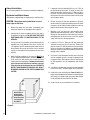
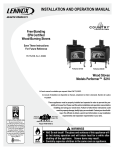
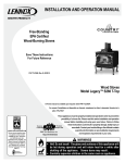
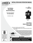
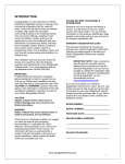
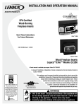
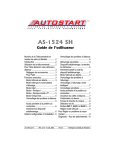
INSTALLATION AND OPERATION MANUAL
Free-Standing
EPA Certified
Wood-Burning Stoves
Save These Instructions
For Future Reference
P/N 775,214M, Rev. C, 05/2008
Striker™ S160
Striker SA160
Wood Stoves
Model Striker™ S160
A French manual is available upon request. Order P/N 775,214CF.
Ce manuel d’installation est disponible en francais, simplement en faire la demande. Numéro de la
pièce 775,214CF.
These appliances must be properly installed and operated in order to prevent the
possibility of a house fire. Please read this entire installation and operation
manual before installing and using your wood stove. Failure to follow
these instructions could result in property damage, bodily injury or
even death. Contact your local building or fire officials to obtain
US
a permit and information on any installation requirements
Report # 050-S-03b-2
and inspection requirements in your area.
WARNINGS
• Hot! Do not touch! The glass and surfaces of this appliance will
be hot during operation and will retain heat for a while after
shutting off the appliance. Severe burns may result.
• Carefully supervise children in the same room as appliance.
General Safety Precautions
1. If this solid-fuel room heater is not properly installed, a house
fire may result. For your safety, follow the installation directions. Contact local building or fire officials about restrictions
and installation inspection requirements in your area.
2. Wear gloves during installation to avoid injury from sharp
edges on the stove and/or its parts.
3. This unit is designed and engineered to burn only dry, wellseasoned wood. Burning wet wood will greatly reduce the
Stove’s efficiency, produce excessive amounts of smoke and
can cause dangerous chimney fires due to creosote buildup.
4. Before opening the door, the draft control must be fully open
to avoid possible combustion flash (ignition of hot volatile
gases as the door is opened).
5. Do not use gasoline, gasoline-type lantern fuel, kerosene,
charcoal lighter fluid, or similar liquids to start or “freshen up”
a fire in this stove. Keep all flammable liquids and combustible
materials 36” from any point of the stove when it is in use.
6. While burning, fuel utilizes oxygen from the air in the room.
Be sure to allow an adequate amount of fresh air into the
room where the stove is burning.
7. The outside surface of the stove will be hot while burning
properly and can set items like clothing and curtains on fire.
Keep furnishings and other combustible materials away from
the stove. Using the heat from the stove to dry wet clothing
can be hazardous if clothes are placed too near the surface
of the stove.
8. Hot while in operation. Keep children, clothing furnishings
and combustible material a considerable distance away. Contact may cause skin burns. Do not allow children to play
near the stove without close supervision. Do not touch the
stove while it is burning. Use extreme caution while the unit
is in use. Surface temperatures become dangerously hot and
can cause serious burns.
9. Do not allow anyone to operate the stove who is not familiar
with the operating instructions.
10. Attempts to achieve heat output rates that exceed stove design
specifications can result in permanent damage to the stove.
Never leave your stove unattended on high burn rates. This
may cause overfiring. Overfiring the stove may cause a house
fire. If the stove glows, you are overfiring.
11. Keep a water hose or hand-operated fire extinguisher close
for safety.
12. Smoke Detectors - Since there are always several potential
sources of fire in any home, we recommend installing smoke
detectors. If possible, install the smoke detector in a hallway
adjacent to the room (to reduce the possibility of occasional
false activation from the heat produced by the stove). If your
local code requires a smoke detector be installed within the
same room, you must follow the requirements of your local
code. Check with your local building department for requirements in your area.
13. Inspect your chimney at least once a month during the burning season to check for soot and creosote accumulations.
Any accumulations over 1/4” thick should be removed by a
professional chimney sweep. Do not attempt to burn out heavy
creosote accumulations with a hot fire. If large accumulations
are occurring, review your burning procedures.
14. If a creosote fire should develop, the fire department should
be called immediately and then attempts should be made to
control the fire until assistance arrives. If a “runaway” fire
should develop causing over-heating of the stove, the door
and draft regulators should be closed immediately. The fire
should die down once deprived of oxygen. After a severe
chimney fire, the complete chimney system should be checked
before further use.
15. Do not operate with a grate or with an elevated fire. Always
build the fire on the surface of the firebrick.
16. Please read this entire manual before you install and use your
new room heater. Failure to follow instructions may result in
property damage, bodily injury, or even death.
17. Check all local building and safety codes before installation.
The installation instructions and appropriate code requirements must be followed exactly and without compromise.
In the absence of local codes the following standards and
codes must be followed.
18. In the U.S.A, install in accordance with the National Fire
Protection Association’s Code, NFPA 211, Standards for
Chimneys, Fireplaces, Vents and Solid-Fuel-Burning Appliances, or similar regulations, may apply to the installation of
a Solid-Fuel-Burning appliance in your area. In Canada, the
guideline is established by the CSA Standard, CAN/CSA-B365M93, Installation Code for Solid-Fuel-Burning Appliances and
Equipment.
19. Do not connect to any air distribution duct or system.
20. WARNING: BURNING IMPROPER FUEL (I.E. CHARCOAL)
CAN RESULT IN CARBON MONOXIDE POISONING, WHICH
MAY LEAD TO DEATH!
21. Carbon Monoxide Poisoning – Early signs of carbon monoxide poisoning resemble the flu with headaches, dizziness, or
nausea. If you have these signs, get fresh air at once! Have
the heater inspected by a qualified service technician. Some
people are more affected by carbon monoxide than others. These include pregnant women, people with heart or lung
disease or anemia, those under the influence of alcohol, and
those at high altitudes.
22. Failure to use manufacturer provided parts, variations in techniques and construction materials or practices other than those
described in this manual may create a fire hazard and void the
limited warranty.
23. Do not make any make-shift compromises during installation.
Any modification or alteration may result in damage to the
appliance or dwelling and will void the warranty, certification
and listings of this unit.
24. These appliances are designed as supplemental heaters.
Therefore, it is advisable to have an alternate heat source
when installed in a dwelling.
Table of Contents
General Safety Precautions..................................................................2
Testing Information............................................................................4
Draft Requirements............................................................................4
Selecting the Proper Venting System.......................................................4
Negative Pressure Warning .................................................................5
Creosote.........................................................................................5
Ash Disposal....................................................................................5
Fuel .............................................................................................5
Burn-In Period..................................................................................5
Paint Curing....................................................................................5
Clearances to Combustibles.................................................................6
Floor Protection................................................................................6
Reduced Clearances..........................................................................6
Alcove Clearances.............................................................................6
Mobile Home Installations...................................................................6
Chimney and Connector......................................................................6
Components Required for Installation......................................................6
Installation Clearances Diagrams...........................................................7
Leg and Heatshield Installation.............................................................8
Outside Air Kit Installation...................................................................8
Stove Installation..............................................................................9
Pedestal Installation..........................................................................10
Post Installation Checks......................................................................11
Brick Installation...............................................................................11
Optional Blower Installation . ...............................................................13
Operating Hints................................................................................13
Starting and Maintaining a Fire.............................................................14
Cleaning Glass.................................................................................15
Operating Techniques and Hints.............................................................15
Getting the Most Out of Your Stove.........................................................15
Maximizing Your Stove’s Overall Efficiency...............................................16
Achieving Clean, Long Burns................................................................16
Maintenance....................................................................................17
Troubleshooting................................................................................18
Do’s and Don’ts................................................................................19
Replacement Parts List.......................................................................20
Accessories.....................................................................................21
Product Reference Information..............................................................22
Testing Information
Selecting the Proper Venting System
This manual describes the installation and operation of the
Striker™ S160 non-catalytic wood heaters. These heaters meet
the U.S. Environmental Protection Agency’s emissions limits for
wood heaters sold on or after July 1, 1990. This heater has been
developed, tested and constructed in accordance with the requirements of UL 1482, ULC S627 and HUD standards and is listed by
OMNI Test Laboratories, Beaverton, OR. It has been approved for
residential, mobile home and alcove installations.
The appliance is merely one component of a larger system. The
other equally important component is the venting system. This is
necessary for achieving the required flow of combustion air to the
fire chamber and for safely removing unwanted combustion byproducts from the appliance. If the venting system’s design does not
promote these ends, the system may not function properly. Poorly
functioning venting systems may create performance problems as
well as be a safety hazard. A draft test should read greater than
.04’ W.C. (inches water column) and less than .08” W.C. As
per NFPA-211 standard (see paragraph below), the installer must
take into account all variables within the installation and install the
appliance in such a manner that satisfies the draft requirements
of the appliance. See Chimney Guidelines below to assist you in
selecting the proper venting system for your installation.
Draft Requirements
Your wood stove is dependent upon a properly functioning chimney
for optimum performance. It is a high efficiency appliance that
loses much less heat up the chimney than older appliances and
fireplaces. For this reason it is important to match the stove to
the chimney. The chimney has two functions: 1.It draws combustion air into the appliance (without air, no fuel
will burn) and
2.It exhausts combustion by-products. Your new Country™ Collection stove is what is known as a “natural draft” appliance.
The appliance depends solely on the natural draft of the chimney
system to draw combustion air into the unit. Draft is the force that
moves air from the appliance up into the chimney. The amount of
draft in your chimney depends on the length of the chimney, local
geography, nearby obstructions and other factors. Too much draft
may cause excessive temperatures in the appliance (overfiring).
Slow or inadequate draft equals poor combustion and possible
smoking problems. The following are some conditions that may
contribute to poor chimney draft: 1.A chimney too large for your appliance.
2.A chimney with not enough height to produce adequate
draft.
3. A chimney with excessive height (this may allow exhaust
to cool too much before exiting, which will stall the rate the
exhaust exits).
4. Offsets in the venting system are too restrictive (see Chimney
Guidelines).
Inadequate draft will cause the appliance to leak smoke into the
room through the stove and the chimney connector joints.
Excessive draft may cause an uncontrollable burn or a glowing
red stove or chimney part.
Overfiring Damage - If the heater or chimney connector glows,
you are overfiring. Other symptoms may include: Cracking,
warping or burning out of components, plated doors may turn
color, stove glass may develop a haze, which will not come off
with cleaning.
Overfiring of a stove is a condition where excessive temperatures
are reached, beyond the design capabilities of the appliance. The
damage that occurs from overfiring is not covered under the
manufacturer’s limited warranty.
Also see Troubleshooting on Page 18.
American National Standards Institute ANSI/NFPA 211, Standard
for Chimneys, Fireplaces, Vents, and Solid Fuel-Burning Appliances - See Draft Section: A chimney or vent shall be so designed
and constructed to develop a flow sufficient to completely remove all
flue and vent gases to the outside atmosphere. The venting system
shall satisfy the draft requirements of the connected appliance in
accordance with the manufacturer’s instructions.
Chimney Guidelines:
• This appliance requires approximately 12 feet minimum of
“effective draw” provided by the venting system. As a rule of
thumb, every 90 degree total direction change in the venting
will result in a loss of approximately 5 feet of “effective draw.” Example: If two 45 degree offsets are used, subtract 5 feet
from the actual vertical vent height to determine your “effective draw.” In this case if you had 14 feet of vertical vent, the
effective draw would only be approximately 9 feet (14 ft. - 5 ft.
= 9 ft.), therefore it may be necessary to add additional height
to the venting system.
• Do not install an offset within the first two feet above the flue
outlet on the appliance.
• In well insulated and weather tight homes, it may be difficult
to establish a good draft up your chimney. The poor draft is
caused by a shortage of air in the house. In this situation an
Outside Air Kit may need to be installed (See Negative Pressure
Warning on Page 5 and Outside Combustion Air on Page 8).
Negative Pressure Warning
This appliance is not designed to be operated in a negative pressure. Very airtight homes with large kitchen exhaust fans, or
homes with furnace cold air returns located in close proximity
to the wood stove or fireplace insert may create negative pressure in the same room as the heating appliance. This can create
dangerous back drafting of the stove and chimney joints, drawing
combustion by-products into the home. Be sure your home has
adequate makeup air to eliminate negative pressures caused by
the above-mentioned sources. Outside air connected to the appliance probably will not resolve such a problem as the stove or
fireplace insert is not the source of negative pressure. Lennox
Hearth Products accepts no liability for damages resulting from
negative pressures described here.
Ventilation Requirements - Provide adequate air for combustion.
The fresh air requirements of this appliance must be met within
the space where it will be installed. Ventilation is essential when
using a Solid-Fuel-Burning heater. In well insulated and weather
tight homes, it may be difficult to establish a good draft up the
chimney (caused by a shortage of air in the home). The lack of air
is caused by many common household appliances which exhaust
air from the home (such as a furnace, heat pump, air conditioner,
clothes dryer, exhaust fans, fireplaces, and other fuel burning appliances). Also, the combustion process of this heater uses oxygen
from inside the dwelling. If the available fresh air delivery in the
dwelling is insufficient to support the demands of these appliances,
problems can result (i.e. excessive negative pressure can develop
in the dwelling which will affect the rate at which this appliance
can draft thus resulting in performance problems. To correct this
problem it may help to open a window (preferably on the windward
side of the house) or install an optional outside air kit.
Creosote
Creosote Formation and Need for Removal - When wood is burned
slowly, it produces tar and other organic vapors, which combine
with expelled moisture to form creosote. The creosote vapors
condense in the relatively cool chimney flue of a slow-burning fire.
As a result, creosote residue accumulates on the flue lining. When
ignited, this creosote makes an extremely hot fire. The chimney
and chimney connector should be inspected at least once every
two months during the heating season to determine if a creosote
build-up has occurred. If creosote has accumulated, it should be
removed to reduce the risk of a chimney fire.
Ash Disposal
Ashes should be scooped out of a cool stove with a small metal
shovel. Ashes should be placed in a metal container with a tight
fitting lid. The closed container of ashes should be placed on
a non-combustible floor or on the ground, well away from all
combustible materials, pending final disposal. If the ashes are
disposed of by burial in soil or otherwise locally dispersed, they
should be retained in the closed container until all the cinders
have thoroughly cooled. Ashes can ignite up to 72 hours after
removal from the stove.
Fuel
This unit is designed and engineered to burn, dry, well-seasoned
wood only.
Dry, seasoned wood is that which has been cut, split and allowed
to dry under a covered area where air is free to flow and circulate
under and around the wood (not under a tarp or plastic). Make
sure wood is not stacked directly on the ground, it may absorb
moisture from the ground. It should be allowed to dry in these
conditions for a minimum of six months, preferably one year
or more. IT MUST BE UNDERSTOOD THAT WOOD CANNOT BE
LEFT IN ANY KIND OF WET OR DAMP AREA OR IT WILL NEVER
BECOME COMPLETELY SEASONED.
Your stove will not operate at the level that it is meant to unless
you use seasoned, dry wood. Do not burn driftwood or wood that
has been in salt water, doing so will void your warranty. Do not
burn treated wood, coal, garbage, cardboard, solvents, or colored
paper. Burning treated wood, garbage, solvents, or colored paper
may result in the release of toxic fumes. This type of burning will
also void your warranty.
Burn-In Period
If your stove has a Gold or Nickel-Plated Door, be sure to clean
it with a household type glass cleaner and a very soft cloth to
remove any fingerprints and residues prior to the first fire and
before any fire if the gold has been handled or soiled. Do not
close the door tightly during the “Burn-In Period.” Also, open
the door frequently (every 5-10 minutes) to keep the gasket
from adhering to the curing paint. Ventilate the house well during these first firings as the paint gives off carbon dioxide and
unpleasant odors. It is recommended that persons sensitive to
an imbalance in the indoor air quality avoid the stove during the
curing process.
Please be patient with the heat output of your stove for the first few
weeks. The steel will go through a curing process that eliminates
moisture, which is deep in the steel and firebrick. This moisture will
reduce initial heat output of your stove and may make it difficult
to start. After you have broken in the paint on the stove it will be
necessary to build hot fires to thoroughly remove the moisture
from the appliance. Running the stove with the draft fully open
for 1 to 1-1/2 hours after starting and adding generous amounts
of fuel during the first week or two should complete the curing
process. We recommend the use of a thermometer attached to
the stovetop or chimney. Temperatures on the connector pipe
should run in the 250-600 degree range. (DO NOT OVERFIRE THE
STOVE DURING THIS PROCESS. IF THE STOVE OR CHIMNEY
BECOMES RED, REDUCE THE AMOUNT OF AIR ENTERING THE
STOVE IMMEDIATELY).
Paint Curing
Your new Striker™ S160 wood stove is painted with a high temperature paint that cures during the first few firings. We recommend that you put your stove through a regimen of three burns.
The first two should last for 20 minutes each at 250 degrees (the
stove should be allowed to cool completely between each burn).
The third should be a burn of at least 450 degrees F. for 45-60
minutes. The paint will become soft, gummy and emit non-toxic
smoke during these burns. After the stove cools down for the third
time, the paint will harden. DO NOT BUILD A LARGE ROARING
FIRE UNTIL THIS CURING EFFECT IS COMPLETE OR YOU MAY
DAMAGE THE FINISH OF YOUR STOVE. Spray can touch-ups
should be done only with a high temperature stove paint (cat. no.
70K99), available from all Lennox Hearth Products dealers.
Clearances to Combustibles
WARNING: BE ABSOLUTELY SURE THE DISTANCE BETWEEN
THE HEATER AND THE SURFACE OF ANY COMBUSTIBLE
CONSTRUCTION IS NOT LESS THAN SHOWN.
Floor Protection
USA - The floor in front and under the heater must be protected
with a minimum of 3/8” (10 mm) thick noncombustible material.
The covering must extend 16” (406 mm) in front of the door
opening of the heater and 8” (203 mm) to either side of the door
opening and 5-1/2” (140 mm) to the rear or to the wall, whichever
is smaller. In all installations a 16” (406 mm) minimum hearth
extension (in front of the stove) is required as measured from the
door opening of the unit.
Canada - The floor in front and under the heater must be protected
with a minimum of 3/8” (10 mm) thick noncombustible material.
The covering must extend 457 mm in front of the door opening of
the heater and 200 mm to either side of the stove body and 200
mm to the rear or to the wall, whichever is smaller. In all installations a 457 mm minimum hearth extension (in front of the stove)
is required as measured from the door opening of the unit.
Reduced Clearances
Clearances to combustible surfaces can be reduced with the use of
listed double wall connector pipe. See the clearances with double
wall pipe on the following page.
Alcove Clearances
Single Wall Pipe - Minimum 48" (1219 mm) width, maximum 48"
(1219 mm) depth. Minimum ceiling height is 84” (2134 m).
Double Wall Pipe - Minimum 44" (1117 mm) width, maximum 48"
(1219 mm) depth. Minimum ceiling height is 72” (1829 mm).
Mobile Home Installations
This appliance is approved for installation into a mobile home
in the USA ONLY!
Installation should be in accordance with the Mobile Home
Construction and Safety Standard, Title 24 CFR, Part 3280 (in
Canada CAN/CSA Z240 MH), or, when such a standard is not
applicable, the Standard for Mobile Home Installations, ANSI
A225.1.
All mobile home installations require an outside air kit (cat. no.
71111 or 71112). The stove must be bolted to the floor and
grounded to the chassis of the mobile home.
WARNING: DO NOT INSTALL IN SLEEPING ROOM OF A
MOBILE HOME.
CAUTION: THE STRUCTURAL INTEGRITY OF THE MOBILE HOME FLOOR, WALL AND CEILING/ROOF MUST BE
MAINTAINED.
Approved Chimney* - Your stove is approved for use with Class
A, UL 103 HT (U.S.) / ULC-S629 (Canada) Listed Residential Type
and Building Heating Appliance Chimney (HT chimney - 2100°
Fahrenheit) and double wall connector pipe from Security™
Chimneys.
Clearances to connector shall be measured from 6" flue collar.
Restrictions apply! Read instructions before installing.
Chimney and Connector
Minimum 6" diameter, minimum 24 MSG black steel connector
pipe with listed factory-built chimney suitable for use with solid
fuels or masonry chimney. Horizontal connection not tested, refer
to local building codes for installation. Restrictions apply! Read
instructions before installing.
Clearance dimensions are to 6” (152 mm) flue collar. If a single
wall connector pipe with shield is used, a 1 inch air space is
needed between pipe and shield. Shield attaches to rear of stove
pipe and must run from stove top to ceiling. Pipe shield shall be
UL listed.
Residential chimney systems must be from the same brands as
listed for mobile homes but connector pipe may be double wall,
single wall or single wall with shield as listed above.
Connector pipe and chimney must be of the same brand.
The chimney connector shall not pass through an attic or roof space,
closet or similar concealed space, or a floor, or ceiling. Where
passage through a wall, or partition of combustible construction
is desired, the installation shall conform to CAN/CSA-B365.
There must be an effective vapor barrier at the location where
the chimney or other component penetrates to the exterior of the
structure. Follow the vent manufacturer's detailed instructions.
IMPORTANT NOTE: See Draft Requirements and Selecting a
Proper Venting System on Page 4 to assist you in choosing the
proper venting system for your installation.
Components Required For Installation
Legs AND Bottom Heat Shield or Pedestal Base.
WARNING: In the event that you remove the blower for any
reason, make sure a cover plate (available from Lennox Hearth
Products) is installed before using the heater. Excessive rear
wall temperatures will result if the stove is burned without the
cover plate. Note: The cover plate is not necessary if a blower
has never been installed because a knock-out will be in place
to act as the cover.
* Other approved chimney brands are Projet, Jakes Evans/GSW,
Dura-vent, Metal Fab, Ameri-Tec, Metalbestos and Industrial
Chimney (ICC).
Installation Clearances - Refer to Diagrams A, B and C
PIPE
INSTALLATION
A
B (1)
C
D (1)
E†
F (1,4)
G (4)
6” Single
Wall
Residential or
Alcove
USA-16”
CAN-483mm
14”
356mm
USA-21”
CAN-610mm
12-1/2”
318mm
8”
200mm
9-3/4”
248mm
USA-18”
CAN-533mm
6” Single w/
Pipe Shield
Residential or
Alcove
USA-10”
CAN-330mm
8”
200mm
USA-18”
CAN-533mm
9-1/2”
241mm
8”
200mm
5-1/2”
140mm
USA-13-1/2”
CAN-419mm
6” Double
Wall
Residential or
Alcove or Mobile
Home*
USA-10”
CAN-330mm
8”
200mm
USA-18”
CAN-533mm
9-1/2”
241mm
8”
200mm
5-1/2”
140mm
USA-13-1/2”
CAN-419mm
H (2)
I (6)
J (2)
K
L (5)
M
Single Wall
PIPE
INSTALLATION
Residential or
Alcove
USA-33-3/4”
CAN-1111mm
USA-47-3/4”
CAN-1340mm
USA-33-1/2”
CAN-1003mm
USA-16”
CAN-450mm
USA 0"
CAN-200mm
84”
2134mm
Single w/
Pipe Shield
Residential or
Alcove
USA-33-3/4”
CAN-1111mm
USA-41-3/4”
CAN-1188mm
USA-33-1/2”
CAN-1003mm
USA-16”
CAN-450mm
USA 0"
CAN-200mm
84”
2134mm
Double Wall Residential or
Air-Cooled
Alcove or Mobile Home*
USA-33-3/4”
CAN-1111mm
USA-41-3/4”
CAN-1188mm
USA-33-1/2”
CAN-1003mm
USA-16”
CAN-450mm
USA 0"
CAN-200mm
72”
1829mm
PIPE
INSTALLATION
Nu
Pu
T (6)
Single Wall
Residential or
Alcove
30"
762mm
36"
914mm
USA-58-1/2”
CAN-1645mm
† USA=8" (200mm) from door opening,
Canada=8" (200mm) from sides and back
of unit
Single w/
Pipe Shield
Residential or
Alcove
30"
762mm
36"
914mm
USA-52”
CAN-1486mm
u Dimensions to Stove Body
Double Wall Residential or
Air-Cooled
Alcove or Mobile Home*
30"
762mm
36"
914mm
USA-52”
CAN-1486mm
Diagram A: Top View-Parallel Installation
A
B
Diagram B: Side View-Alcove & Parallel Installation
48”
Maximum
Depth
E
L
C
N
D
* Mobile Home - USA only
6” Ø
Flue Collar
H
I
72" Min.
P
M
†E
*L
K
Floor Protection
†E
J
Floor Protection
I
F
G
G
F
T
Diagram C: Top View Corner Clearance,
Diagram C: Top
Stove and Flue to Wall
View-Corner
Installation
H
Floor Protection
K
J
Footnotes:
1- These dimensions to the stove body are for reference only. Actual
distances should be measured from the stove’s flue collar.
2- Minimum noncombustible hearth pad dimensions.
3- Shield shall be attached to the rear of the stove pipe with a 1” air
space and must run from the top of the stove to the ceiling.
4- Not applicable to alcove installations.
5- In corner applications, when installed at minimum back wall clearances, the required floor protection is dimensioned off the back
plane of the stove, therefore the floor protection required off the
back corners (at a 45 degree angle) only needs to extend to the
wall. This situation will only occur in CANADA installations.
6- Reference dimension only, to assist in planning the installation.
Clearances to connector pipe shall be measured from the flue
collar of the stove.
Leg and Heatshield Installation
Note: The threaded rods used to bolt the legs to the stove are
packaged with the heatshield, as a heatshield is required when
a stove is installed on legs.
Residential and Mobile Homes
(Bolting down and grounding of stove are required only in
mobile homes).
Open all cartons, if any and remove the contents upon receipt
and check for any damaged or missing parts. If there is hidden
damage, notify your freight company or Lennox Hearth Products
dealer immediately.
CAUTION: Wear gloves during installation in case of
sharp edges on the stove.
Heat Shield
Mounting Holes
Front
Figure 2
Air Channel
Leg Installation
Outside Air Kit Installation
1. Carefully place stove on its back. Be careful not to scratch
the stove, use a piece of cardboard or carpet to protect
the back of the stove.
2. Mount all four legs as shown in Figure 1.
3. First, screw the threaded rods into the holes at the four
corners on the bottom of the stove. Screw the threaded
rods into the firebox three full rotations or 3/16 to 1/4”
(if the rear rods are screwed in too far they will lift the
bricks off the bottom of the stove). Use a washer and nut
to secure the leg. Be sure the legs are mounted squarely
on the firebox bottom. Tighten nuts securely.
4. Use the two bolts and washers provided with the heatshield
kit to mount the heatshield as shown in Figure 2.
5. Do not over tighten the heatshield mounting bolts as it
may bend the heatshield.
To install the “Outside Air Kit,” position the clip so that the nut is
directly above the hole punched in the back of the heatshield (See
Figure 3). Install the outside air adapter box on the stove by sliding it into the air channel located between the bottom heatshield
and the stove bottom until the oblong ring is approximately 1/4”
from the rear edge of the lower heatshield. Make sure the ring is
facing down. Thread the 1/4” bolt up through the nut in the clip
until snug against the adapter box.
Expanded View of Clip
Line up the hole in the clip with the hole in the
rear center of the bottom heatshield
Threaded
Rod
Washer
Nut
Clip
1/4” Bolt
Figure 3
Figure 1
To locate the hole in the hearth for outside air, mark a 4” circle on
the hearth. The circle’s center should be 2-3/4” directly back from
the center of the flue outlet and 5/8” to the left side.
NOTE: DIAGRAMS & ILLUSTRATIONS ARE NOT TO SCALE.
Stove Installation
1. If not previously installed, install floor protection and move
the heater into the desired location.
2. Position the stove on your floor protection in the exact location
where it is to be located, making sure all minimum clearances
are met.
3. If you are installing outside air on your stove, mark a 4” circle
on the floor protection just below the oblong ring. When
cut out, this hole will accommodate the flexible outside air
tube.
4. If the stove is to be fastened to the floor, locate the hold down
brackets inside the leg box and mark the floor protection
below the holes in the brackets.
5. If you are installing outside air on your stove, remove the
stove and cut the floor protection and the floor where the
4” air tube circle had been previously drawn. If the stove is
to be fastened to the floor, drill 1/2” holes through the floor
protection only, at the marks that were for fastening the
stove to the floor if so desired. Slip the flexible outside air
tube through the hole in the floor, leaving 1” of tube above
the floor protector surface, using tape to hold it in place.
6. Place the stove on the floor protection so that the previously
cut or drilled holes line up. Attach the stove to the floor with
the lag bolts if so desired.
7. If you are installing outside air on your stove place the hose
clamp over the flexible air tube and slide the tube up over the
4” ring on the outside air adaptor box and tighten the hose
clamp. Push the outside air adaptor forward 1/4” until full
contact is made with the lower heatshield. Tighten the 1/4”
bolt until the adaptor box is held firmly in place. Use silicone
sealant to create a seal between the flexible air tube and your
floor protection.
8. If it is necessary to level, secure or ground your stove, use
the holes in the bottom of the leg for those applications. To
level the stove on Olympic cast legs, locate the front leg that
is not touching the hearth pad. Insert the allen head screw
through the slotted washer (supplied with the legs) and into
the threaded hole in the bottom of the leg. See the drawing to
the right. Push the slotted washer down until it touches the
hearth pad and then tighten the screw into the leg. Should any
other leg not be resting on the hearth pad, install a washer
and screw in that leg as well.
9. Install bricks and baffle as per instructions on Page 11. It is
highly recommended that the baffle be assembled before the
chimney is installed so that the insulating fiber blankets can
be adjusted into place through the flue collar.
10. If installed into a mobile home, the stove shall be grounded
to the mobile home chassis with a #8 AGW copper wire or
equivalent.
11. For residential installations, install the first section of stove
pipe with the crimped end going down inside the flue collar
on the heater. Continue with your stove pipe, installing each
section-crimped end down. Make the final connection to your
chimney. Your dealer carries the necessary pipe and fittings
to connect to the various listed factory-built chimneys. YOUR
CHIMNEY INSTALLATION MUST COMPLY WITH LOCAL
BUILDING AND FIRE CODES.
12. Be sure to fasten each stove pipe connection with at least 3
sheet metal screws.
13. Install chimney as per manufacturer’s instructions. Some
brands of pipe may require removal of the spacer ring in the
flue collar.
14. All horizontal runs of pipe should be as short as possible and
are required by NFPA No. 211 to have an upward pitch or rise
in the same direction the smoke travels of no less than 1/4”
to the linear foot. The connector pipe must meet minimum
clearances in any direction to walls or other combustible
materials. It must attach to a listed double wall metal chimney
at least 6” in diameter or to a masonry chimney with a flue
passage of at least 48 square
inches.
15. It is required that a chimney
connector pipe not extend
further than the inner wall of
the flue when it is connected
to a masonry chimney and
that it either be cemented to
the masonry or be installed
without cement in a thimble
connected to the masonry
wall. When the connector is
inserted into a thimble, the
joint must be tight enough so
that it will not be dislodged in
Insert the allen
normal use.
head screw
Install connector at no less than through the
slotted washer
the minimum clearances from
the ceiling when using a 90degree elbow to pass through
combustible constructions.
16. Chimney connector pipes
should never pass through a Figure 4
floor, ceiling, fire wall, partition, or combustible construction
of any type unless certain precautions are taken. The best
method is to use a listed thimble and a listed chimney in
accordance with the manufactures directions. NFPA No. 211
gives approved methods for passing a flue pipe through
combustible constructions.
NOTE: DIAGRAMS & ILLUSTRATIONS ARE NOT TO SCALE.
Pedestal Installation
(For ash drawer pedestal see instructions included with pedestal)
Residential and Mobile Homes
(Bolting down and grounding are required only in mobile homes)
CAUTION: Wear gloves during installation in case of
sharp edges on the stove.
1. Remove the heater from the carton, if packaged, upon
receipt and check for any damaged or missing parts.
5. If required, install the Outside Air Kit (cat. no. 71112) as
per the following instructions. To locate the hole in the
hearth for outside air mark and cut a 4” (102 mm) hole in
the hearth. The hole’s center should be 3” (76 mm) directly
forward from the center of the flue outlet or locate as per
the instructions below.
6. Position the stove on your floor protection in the exact
location where it is to be located, making sure all minimum
clearances are met. Mark the floor protection where the
pedestal will be located, then remove the stove.
2. Carefully put the stove on pedestal with the open end of
the pedestal facing the rear. DO NOT LEAVE THE STOVE
UNATTENDED UNTIL IT IS BOLTED SECURELY TO THE
PEDESTAL.
7. Make four 1-1/2” (38 mm) cuts in one end of the corrugated tube and fold the flaps back. Cut a 4” (102 mm) hole
through the floor protection and the floor and insert the
corrugated tube into the hole. Cover it with the supplied
screen and fasten it to the floor protector.
3. Line up the holes in the brackets on the pedestal with the
threaded holes in the bottom of the stove. Use the two
1/2” long bolts and 3/8” standard washers to bolt the stove
to the pedestal. Be sure to see that the stove is mounted
squarely on the pedestal before tightening the two bolts
securely.
8. Locate the 11-1/2” x 14” (292 mm x 356 mm) metal plate
and paint to match the stove if necessary. Position this
piece so that the 14” (356 mm) dimension evenly overlaps
the lips on the back of the pedestal (see drawing below).
Attach this plate to the back of the pedestal with the selftapping screws supplied.
4. When installing a pedestal on this stove you MUST plug
the four leg mounting bolt holes, located on the bottom
of the stove in the four corners, with the bolts that were
used to mount the shipping legs. The two rear bolts should
not be installed more than two full rotations to prevent
lifting the bricks off the bottom of the stove. FAILURE TO
INSTALL THESE FOUR BOLTS PROPERLY WILL RESULT
IN REDUCED CONTROL OF THE STOVE’S COMBUSTION
SYSTEM!
9. If the stove is to be fastened to the floor, attach the stove
with the supplied lag bolts, through the pedestal base
on opposite sides, attaching them into the floor beneath
the floor protection. Seal any irregularities with silicone
sealer.
10. If installed in a mobile home, the heater shall be grounded
to the chassis with a #8 AGW copper wire or equivalent.
11. Install bricks as per instructions on Pages 11 and 12. It is
highly recommended that the baffle be assembled before
the chimney is installed so that the ceramic fiber blankets
can be adjusted into place from the flue outlet.
12. Install chimney as per manufacturer’s instructions.
Block Off Plate is
Required When
Installing Outside
Air Into Unit (Plate
is Included With
Kit # OAK-P)
Figure 5
10
NOTE: DIAGRAMS & ILLUSTRATIONS ARE NOT TO SCALE.
Post Installation Checks
1. Check that all chimney pipe joints are securely fastened.
2. Check that the heater is securely fastened to the floor (if
applicable).
3. Make sure the intake vent has clear access to outside air
(if applicable).
4. Make sure the outside air vent has been sealed properly
to keep rodents out (if applicable).
5. Be sure all roof flashings are watertight.
6. Be sure the stove is properly grounded (if applicable).
FOR YOUR OWN PROTECTION AND INSURANCE
PURPOSES, HAVE YOUR CHIMNEY AND CONNECTOR
PIPE INSTALLATION INSPECTED BY YOUR LOCAL
BUILDING CODE AUTHORITY OR FIRE MARSHAL
BEFORE STARTING A FIRE IN YOUR STOVE. NOTIFY
YOUR INSURANCE COMPANY.
Brick Installation
CAUTION: Wear gloves during brick installation in
case of sharp edges inside the stove.
Note: Installation of the baffle bricks and insulating blanket is
easier when you can still access the flue outlet, (before connecting
the flue pipe). Be sure the insulating blanket is placed flat on
the bricks so as not to block the flue. Use a ruler or a piece of
kindling to reach over the blanket to be sure it is completely flat
on top of the baffle bricks.
Measure bricks before installing, as per list of dimensions on
next page, to be sure the correct bricks are installed in the correct location.
1. Install bricks #1-18 in the numbered sequence shown in
Figure 6 on Page 12.
2. Next, install bricks #19 and 20 into the rear stainless steel
baffle support (see Figures 7 and 8 on Page 12).
11
3. Next, install baffle bricks #21-24 by sliding the back of
each brick over the center tube and support until the front
of the brick clears the front tube and support. Then lift
the front of the brick above the front support and tube
and slide it forward as far as it can go (very important),
it will hit the front of the stainless support when it is fully
forward. The rear of the bricks sit on top of bricks #19-20
(Figures 7 and 8).
17D
4. Carefully slip the ceramic blanket up over the front of
the front stainless support and bricks #21-24. Grasp the
edge of the blanket and slide it back until the front of the
blanket is flush to the front of bricks #21-24 (Figure 7).
Shake the blanket gently from side to side to get it to lay
flat. Be sure the ceramic blanket is directly on top of the
baffle bricks and that it does not hang out past the front
of the baffle as shown in Figure 7, also see note on Page
11.
18B
Brick Sizes
3
D
2
F
1
F
8
A
7
F
11F
12A
15G
9
F
10
F
14F
13F
4
F
5
F
6
D
A = 4-1/4” x 9”
B = 2-1/4” x 8-7/8”
C = 3-1/2” x 9”
D = 2-1/4” x 9”
E = 1-1/2” x 8-7/8”
F = Full Brick (4-1/2” x 9”)
G = 1-1/2” x 9”
H = 3-1/2” x 8-7/8”
16E
Figure 6
Ceramic Fiber
Blanket
Baffle Bricks Top View
19 C
Stainless
Steel Baffle
Supports
21 F
Figure 8
Figure 7
12
NOTE: DIAGRAMS & ILLUSTRATIONS ARE NOT TO SCALE.
20 H
22 A
23 F
24 F
Optional Blower Installation
A blower, catalog number 71000, can be installed on the stove
to improve hot air distribution throughout the room.
To install the blower:
1. Remove all the contents from the blower box. Included
with the blower should be a blower speed control.
2. Remove the screws in the round knock-out plate on the
back of the stove. Bend the knock-out plate back and forth
until it can be removed.
3. Mount the blower as shown below. Make sure the cord is
at the bottom when mounted and that it does not touch the
stove anywhere. Remove the four screws from the back of
the stove. Use one of the four screws with a washer on it
and attach the blower through one of the four mounting
legs on the blower housing. Check to make sure that the
fan blade does not touch the large hole in the rear heatshield. (Spin it to check all directions). Finish attaching
the blower with the other three screws. Tighten the screws
moderately tight but do not over tighten as you may strip
the holes out.
4. Plug in the fan speed control into the nearest outlet, then
plug the blower cord into the speed control. Do not route
the fan power cord under the stove or allow it to come in
contact with any surface of the stove. Read the section
Starting and Maintaining a Fire for proper fan operating
instructions on Page 15.
WARNING: In the event that you remove the blower for
any reason, make sure a cover plate (available from
Lennox Hearth Products) is installed before using the
heater. Excessive rear wall temperatures will result
if the stove is burned without the cover plate. Note:
The cover plate is not necessary if a blower has never
been installed because a knock-out will be in place
to act as the cover.
Operating Hints
1. Burn only dry, well-seasoned wood for maximum heat
output. In some states it is illegal to burn wet wood or
anything other than clean, dry wood products.
2. Your stove is designed to operate with the door closed!
Operate only with the door shut tightly at all times except
when loading wood.
3. DO NOT hit or move the baffle brick while loading wood.
Occasionally check the baffle. Make sure the insulating
blanket is always flush with the front of the baffle brick.
Loading oversized logs may dislodge the baffle bricks.
4. CAUTION: THE DRAFT CONTROL MUST BE FULLY OPEN
BEFORE OPENING THE DOOR TO AVOID POSSIBLE COMBUSTION FLASH!! (Ignition of hot volatile gases as the
door is opened).
5. Feeding excessive amounts of fuel to the stove should be
avoided. It is important to supply it with sufficient draft and
fuel to maintain a moderately hot fire. If, during overnight
burns, heavy creosote deposits develop inside your stove
and on the door, the draft is set too low - review your
burning habits!
Figure 9
WARNINGS
The blower must be plugged directly into a properly
grounded three-prong receptacle, 120 VAC, 60 Hz, single
phase. Do not cut or remove the grounding prong from
this plug. Do not route power cord under or in front of
appliance.
Installation must be in accordance with National Electrical Code, ANSI/NFPA 70 - latest edition. In Canada,
the current CSA C22-1 Canadian Electrical Code - latest
edition.
CAUTION
Be careful not to abuse door assembly by striking or
slamming it. If the door assembly or glass is broken or
damaged, they must be replaced with factory original
parts before heater can be safely operated. Use only
components provided by the manufacturer as replacement parts.
DANGER: Disconnect power before servicing blower.
NOTE: DIAGRAMS & ILLUSTRATIONS ARE NOT TO SCALE.
13
4.
Light the paper and allow sufficient time for the kindling to
become fully engulfed in flames. Close the door. Your door may
or may not need to be left slightly open during this process,
depending on your stove model and chimney draft. Once
the kindling is burning well, larger pieces of wood may be
added, then the door should be closed.
Do not operate the stove with the doors open or ajar, as
this will produce extreme temperatures within the stove.
Damage caused from over-firing is not covered under the
manufacturers limited warranty.
5. For best results, use smaller pieces of wood to get the
stove temperature very high before loading larger wood
for sustained burns. If necessary, crack the door to allow
ignition of the fuel charge. Now you can add larger pieces
of wood and after several minutes of high burn, set the left
control for the desired heat output. Check the exhaust in
about 15 to 20 minutes. Large amounts of smoke indicate
an improper burn setting (either too high or too low). Adjust
and recheck in 5 to 10 minutes.
Figure 10
Starting and Maintaining a Fire
Be sure to clean the Nickel or Gold Plated door with a household
type cleaner and a very soft cloth to remove any fingerprints
and residues prior to the first fire.
6. After your stove has been thoroughly preheated, your
blower can be switched on. When refueling your stove,
turn the blower off for the first 30 minutes. On low and
medium-low burns run the blower on low. These burn rates
would be achieved by operating the stove with the draft rod
fully pushed in to up to 3/4” open (out). To do this, turn
on the blower at the speed control and rotate the control
all the way to the right. On medium-high and high burns
you may run the blower on high. These burn rates would
be achieved by opening the draft rod further than stated
previously. To do this, turn on the blower with the speed
control and do not rotate the switch after it clicks on.
1. NEVER USE FLAMMABLE LIQUIDS TO START OR REKINDLE A SOLID FUEL FIRE!!
2. Fully open the primary draft control by pulling the 1”
plastic knob out on the left side (lower front corner) until
it stops (away from the stove). This control determines
the amount of air entering the stove. Pushing it toward
the stove reduces the burn rate in the firebox. For your
convenience, the rod on this control is marked with
four grooves to assist you in obtaining repeatable burn
rates.
3. Place a small amount of crumpled paper in front of the
firebox and cover it with a few pieces of kindling.
14
NOTE: DIAGRAMS & ILLUSTRATIONS ARE NOT TO SCALE.
Cleaning Glass
SEE MAINTENANCE ON PAGE 17 FOR GLASS CLEANING TIPS
The operator plays an important part in keeping the glass clean and
free of build-ups. The first and most important part the operator
plays is making sure to burn only well-seasoned firewood. Wet
wood = Dirty glass. Keeping your glass door clean is partly accomplished by the air wash system of the stove, which sends clean,
fresh air for combustion, over the window before it enters the fire.
The high temperatures inside the firebox also keep the glass clean.
No stove door stays perfectly clean. The following are methods
for keeping build-up on your glass to a minimum. When properly
installed and operated by a knowledgeable operator, your glass
door should require very little maintenance. Do not expect to get
extremely long burn times and keep the window perfectly clean.
Cool temperatures cause condensation of unburned volatiles on
the glass. If your glass gets very dirty during overnight burning,
try preheating the stove a little longer before damping it down for
an overnight burn. Also, don’t damper your stove down as low
because you’ll get more heat for your money by burning a little
hotter for a slightly shorter time.
The air wash system will perform at its best at medium burn rates.
Some stove models will self clean by burning very hot fires but
be sure not to over-fire the stove. If it glows red it is over-fired.
Over-firing a stove also causes the window to soot up. Extremely
hot fires with fresh wood may cause the flow rate to exceed one
foot per second, which is as fast as a flame can burn. This is why
a candle goes out when you blow on it. Blow on it gently and it
burns brightly. Blow on it hard and it goes out. This will cause
excessive exhaust emissions and your window to soot up, as the
stove is unable to burn the gases emitted from the wood. Try
slowing the stove down a little by closing the damper somewhat
as it warms up.
CAUTION
Cleaning Glass: Ensure appliance is cold prior
to cleaning glass. A commercial glass cleaner
designed for stoves is recommended. Do not use
abrasive cleaners. Do not clean with any materials,
which may scratch or otherwise damage the glass.
Scratches on the glass can develop into cracks or
break. Inspect the glass regularly. If you detect a
crack, extinguish the fire and contact your dealer
for a replacement.
Operating Techniques and Hints
Recent developments in wood-burning technology have made
wood-burning a cleaner and more convenient way to heat your
home. Overall efficiency in a wood-burning appliance is a combination of combustion efficiency and heat transfer efficiency. Whether
heating your entire home, or just a room or two, your understanding
of how to best operate your stove or insert will enhance its overall
efficiency and performance. What this can mean to you is longer,
cleaner burns, less wood use and more heat.
Getting the Most Out of Your Stove
The following sections will outline techniques you can use to “get
the most out of your stove.” Please read them carefully.
Keeping freshly loaded wood away from the window will also help.
Load fresh logs in the rear of the firebox. Build-up tends to occur
first on the right side of the window. This is caused by the swirling motion of the exhaust gases similar to water running down a
drain. Keep fresh logs further back on the right side of the firebox
to help prevent this problem.
Understanding how your Country™ Collection stove works should
help you keep your glass door very clean, but as stated: no glass
door stays perfectly clean. We hope this information is helpful in
keeping your glass door clean so that you may enjoy many hours
viewing your high efficiency stove. For more information, contact
your Lennox Hearth Products dealer.
15
1. Thoroughly preheat your stove before slowing the burn
rate by closing the draft control.
2. Measure the stove temperature at the hottest point on
the stove top or face. Use this information to repeat burn
rates.
3. Once preheated, add wood (if needed) and partially close
the draft control (lower left).
4. Operate your stove as much as possible in the low to
medium burn ranges.
5. Do not lower the draft setting so low as to completely extinguish the flames in the firebox. Check for at least some
small flames 20 minutes after setting the draft control.
6. Do not continually operate your stove in the high (wide
open) setting. This wastes wood by carrying a great deal
of heat up the chimney and can damage your stove and
chimney.
7. Go outside and check your chimney. More than a very
small amount of smoke indicates wasted heat, creosote
build-up and pollution.
Maximizing Your Stove’s Overall Efficiency
It is important to know that for high, combustion efficient, clean
burns, you will need to have sufficient temperatures inside the
firebox for thorough combustion. The best method for determining
if you have sufficient temperatures is to watch the brick lining in
your firebox. When you first light your stove, the bricks will turn a
dark brown or black. After 20 to 30 minutes of a hot fire, most of
the bricks should return to near their original light brown or yellow
color. This means the bricks have reached a high enough temperature for your stove to achieve high combustion efficiency.
Second and just as important, is achieving a high level of heat
transfer efficiency. Slowing the rate of flow through the stove or
insert enhances heat transfer, thus allowing more time for heat to
be transferred into your home. To do this, be sure to thoroughly
preheat your stove and then reduce the amount of primary air
by closing the draft control (lower left) to about 1/2 to 3/4 open.
This will decrease the excess oxygen in your flue, which carries
heat up your chimney, but should still be enough air to allow the
stove to produce its maximum heat output. (More air may produce
a lightly greater amount of heat, but will greatly increase wood
consumption). When the area being heated reaches a comfortable
temperature, slow the burn rate by closing the control to further
improve heat transfer.
To get the most out of your Country™ Collection stove, you will
need to combine good combustion efficiency with good heat
transfer practices. The following are some tips on how to operate
your stove to achieve the highest overall efficiency.
Achieving Clean, Long Burns
To achieve long burn times, after having thoroughly preheated
the stove, let the stove top cool down to 275 to 400 degrees (on
Elites, locate thermometer on the face of the insert just above
the door). Now load the firebox and set the draft control. At this
point, you may need to burn the stove with the draft open for a few
minutes to ignite the wood. All Country Collection stoves are EPA
tested for emissions at low burn with the air control completely
closed. Whether or not you should burn your stove with the air
control completely closed will depend on the following factors.
16
* How you load your wood
* Your chimney type, height and draft
* Your wood type and its moisture content
* The temperature of the stove
* Which model stove or insert you have
Experiment with different loading configurations to achieve
longer burns. Try loading the wood from side to side and nesting
it in the ashes to prevent airflow under and around the wood. Fresh
wood should be loaded to the back of the firebox or to the sides.
Hot coals or half burned wood should be brought towards the front
of the firebox. The way you load your wood can seriously affect
burn times. If the new load does not ignite within a few minutes,
try crisscrossing the load to allow more airflow around the fire,
or try a slightly hotter stove temperature.
Determining the lowest setting for efficient low burns. This
will require some experimentation on your part. Try closing the
air control all the way with the stove temperature at 325 to 350
degrees. If the flames are completely extinguished, open the air
control halfway and then slowly close it until there is only a small
amount of flame. It is important to check the stove about 20
minutes after setting the draft control as it takes this long for the
stove temperature to stabilize. There should still be some small
flames on or above the wood load.
Use 325 degrees as a starting point. You can try starting temperatures 25 degrees higher or lower to achieve desired burn
times, start 25 degrees lower if the stove burns the wood too
quickly or 25 degrees higher if there are no flames in the firebox
for more than a few minutes after loading the wood. You may or
may not need to burn the stove with the air control open for a few
minutes prior to setting the draft for a low burn, this will depend
on the factors mentioned above. Be sure not to smolder a fire
overnight. Check your chimney for large amounts of smoke as
this indicates very poor combustion.
It is important to realize that stove technology has changed.
Stoves have changed a great deal in the last few years. This has
led to substantial changes in the methods of operation in new
stoves as compared to older stoves. In old stoves without full
brick linings and ceramic insulation, the rule was “get the stove
as hot as possible before setting the draft on low for overnight
burns.” On newer, high technology Country™ Collection stoves,
this is not necessary. Although it is still important to have the stove
hot enough to burn efficiently, it will require less preheating. Once
you have determined your optimum operating temperatures for
various burn rates, we believe you will find your stove an extremely
convenient way to achieve your heating needs.
Do not reload the stove for long burns when the stainless
secondary tubes or baffle supports are glowing red, or when
the stove is uncomfortably hot to load. This indicates the stove
is too hot to load for a long burn. Also, do not load wood for a
long burn on a deep bed of hot coals. Try stirring the coals a few
minutes before loading the stove for a low burn to allow some of
the unburned coals time to burn.
Maintenance
Door Hinges: If door hinges need lubricating, use an anti-seize
compound (never use oil) available from your Lennox Hearth
Products dealer.
Door Latch: If your door latch fails to latch tightly and the gasket
is in good condition, place a length of pipe (cheater bar) over the
inside portion of the door handle and bend slightly toward the door
until the proper adjustment is obtained. If the door handle does not
close easily, apply high temperature anti-seize to the striker.
Door Gasket: Periodically check gasket to make sure it is not
over-compressed. If compressed, replace with a special woven
Door Rope. (Don’t try substituting rope, only use special Lennox
Hearth Products Door Rope).
Gold or Nickel Plated Door: Clean only with household
type glass cleaner and a very soft cotton cloth. Other products
may damage brass, paint and gaskets.
INSULATING BLANKETS: Your insulating blanket should be inspected during every chimney cleaning. If the blanket is compressed
or heavily stained, it should be replaced. Heavy creosote stains or
matting is an indication of improper use and your burning habits
should be reviewed.
Glass Cleaning: Only clean glass with products specifically
made to use on wood stoves. Other products could damage gaskets
and paint. Never scrape glass with a razor blade. This can pit the
glass and make it impossible to clean in the future.
WINDOW GASKET: The window gasket can be checked by running the flame of a match near the gasket and around the door.
If the flame is drawn in around the window, the gasket should
be replaced.
DOOR HANDLE: Door handle may become tight as you use the
stove. Free the handle up by using dry graphite supplied with the
stove. The directions are included with the graphite.
WARNING
Inspect and clean chimney and connector frequently.
Under certain conditions of use, creosote buildup
may occur rapidly.
17
Troubleshooting
Problem
Solution
POOR DRAFT:
Extend chimney in length or have the chimney realigned to the proper size flue. Oversized chimneys normally have poor drafts. Remember, the stoves’ draft depend solely on the natural draft of the chimney (See
drafting section on Page 4). If your stove is not drafting properly, your chimney is the problem. All stoves
are thoroughly tested to ensure proper draft with the correct size chimney flue.
EXCESSIVE DRAFT:
With better chimneys being more common, excessive draft can be an issue. Alleviate excessive draft by
slowing the burn rate of the stove once it has reached proper operating temperature (See Maximizing Your
Stoves Overall Efficiency on Page 16).
DIRTY GLASS:
1) Burn smaller, hotter fires and check to make sure you are not setting the draft down too far with the draft
control.
2) Make sure your wood is well-seasoned and dry (not open to rain - see Creosote and Fuel sections on
Page 3).
3) See Poor Draft section (above) and Cleaning Glass on Page 15 .
SMOKES WHEN
DOOR IS OPEN:
1) If smoke is entering the room, check to make sure your baffle bricks are properly installed
and that the insulating blanket is pushed back flush with the front of the baffle brick.
2) Check the chimney for blockage due to creosote (see Chimney and Creosote sections on Pages 3 and 4).
3) Check draft (See POOR DRAFT section above).
WOOD BURNS
TOO FAST:
1) The draft control must be closed further.
2) Add fuel at lower firebox temperatures.
3) Load wood side to side and reduce the flow of air under wood.
4) The door seal may need replacing, check for leakage.
5) See “Excessive Draft.”
POOR HEAT
OUTPUT:
1) Check your wood. Wet, moist, unseasoned wood will not produce heat.
2) Your stove needs to be seasoned (moisture removed from the steel and brick). Continue to burn a fire.
It normally takes from one to three weeks of burning to season your stove (See Burn-In Procedures on
Page 5).
3) See Excessive Draft section above.
PAINT GIVES OFF
ODOR (smoke):
18
Paint is tempering-in. Burn only moderately hot for the first few days until paint is fully cured.
Then burn a very hot fire to cure any paint that may not easily cure. Open windows or door to ventilate (See
Burn-In Procedures on Page 5).
Do’s and Don’ts
DO NOT: Install or operate this stove before reading this manual.
DO NOT: Close the draft beyond the point at which the flames are completely extinguished.
DO NOT: Open the stove door without fully opening the draft first.
DO NOT: Burn driftwood or wood that has been in salt water. This includes some mill ends and scrap lumber that has been floated in
salt water on the way to the mill. (This will void your warranty).
DO NOT: Handle the Nickel or Gold faceplate unnecessarily. Use the door handle only.
DO NOT: Force oversized logs into the firebox as this may dislodge the baffle assembly.
DO NOT: Close the door tightly during Burn-In Period.
DO:
Be sure to clean any fingerprints from the Gold or Nickel faceplate before burning the stove. Clean the Gold or Nickel door
only with a household type glass cleaner and a very soft cloth.
DO:
Consult local building department if other than recommended clearances are desired.
DO:
Read instructions for the brick baffles occasionally to ensure you have not bumped or moved them out of place when loading
wood.
DO:
Check the chimney and baffle a minimum of every 3 months to make sure they are clean.
DO:
Burn seasoned, dry wood only! (RAIN = WET WOOD)
DO:
Complete and return your warranty card.
DO:
Open the door frequently during Burn-In Period to keep gasket from adhering to the curing paint.
DO:
Enjoy the warm feeling of your new Country™ Collection stove.
19
Replacement Parts - Model S160
Contact an Authorized Lennox Hearth Products dealer to obtain
any of these parts. Never use substitute materials. Use of
non-approved parts can result in poor performance and safety
hazards.
BLOWER PARTS
Cat. No.
H5658
Description
Cat. No.
Description
71072
Arch / Plain
71073
Arch / Sailboat
71069
Arch / Cattail
71070
Arch / Evergreen
71071
Arch / Floral
Single Black Cascade Steel Legs (4 per pkg.)
LEG PARTS
Fan Blade (FSB700)
H5657
Fan Cage (FSB700)
70003
H5660
Blower Power Cord (FSB700)
70000
Single Black Olympic Cast Legs (4 per pkg.)
Speed Control (FSB700)
70001
Single Gold Olympic Cast Legs (4 per pkg.)
H5621
Single Nickel Olympic Cast Legs (4 per pkg.)
Single Brushed Gold Olympic Cast Legs (4 per pkg.)
H5656
BRICKS, BLANKET AND GASKETS
H5642
Firebrick (replacement - specify size)
70007
H5576
Firebrick Letter A - 4-1/4” x 9” (3 per stove)
70008
Single Brushed Nickel Olympic Cast Legs (4 per pkg.)
H5649
Heat Shield / Leg Hardware Bolt Kit
H3095
Firebrick Letter B - 2-1/4” x 8-7/8” (1 per stove)
H5614
Firebrick Letter C - 3-1/2” x 9” (1 per stove)
H5607
Firebrick Letter D - 1-3/4” x 9” (4 per stove)
H5579
Door Back and Handle (for Trad door) (door gasket included)
H5597
Firebrick Letter E - 1-1/2” x 8-7/8” (1 per stove)
H5578
Door Back and Handle (for Arch door) (door gasket included)
H5612
Firebrick Letter F - 4-1/2” x 9” (9 per stove)
H5629
Upper Hinge Pin
H5604
Firebrick Letter G - 1-1/2” x 9” (1 per stove)
H5628
Lower Hinge Pin
H5598
Firebrick Letter H - 3-1/2” x 8-7/8” (1 per stove)
H5626
Upper Hinge Pin E-Clip
H5610
Complete Baffle Brick Set
H5577
Set of 6 screws and 6 washers for door assembly
H5609
Complete Cut Brick Set
(Only need 4-1/2” x 9” bricks to finish)
H3103
Complete Stainless Secondary Burn Setup
(includes tubes and all mounting hardware)
H5608
Complete Brick Set
H3104
Front Stainless Secondary Burn Tube with Support Baffle
H5641
Ceramic Blanket (20” x 11” x 1/2”)
H3105
Middle & Rear Stainless Secondary Burn Tube with Support
H5640
Glass Gasket 5 feet needed (per foot)
H5627
Removable Inner Flue Collar Ring
H5639
Door Rope 7/8” 5 feet needed (per foot)
H5573
Gold w/ Rivets
Nickel w/ Rivets
FACEPLATES / TRADITIONAL
METAL COMPONENTS
NAMEPLATES
71057
Traditional / Black
H5572
71058
Traditional / Gold
H5643
71059
Traditional / Nickel
71148
Traditional / Brushed Gold
71145
Traditional / Brushed Nickel
FACEPLATES
Rivets for Nameplates (2 per)
OUTSIDE AIR KIT REPLACEMENT PARTS - LEG
0-0300-0330-0015 , 15” of 4’ Aluminum Flex Tubing (per
foot - 1.25’ needed)”
H5662
Leg Kit Plenum Box
OUTSIDE AIR KIT REPLACEMENT PARTS - PEDESTAL
71060
Arch / Black
71061
Arch / Gold
H5516
15” of 4’ Aluminum Flex Tubing (per foot - 1.25’ needed)
71062
Arch / Nickel
H5565
6” x 6-1/2” Rodent Screen
71147
Arch / Brushed Gold
H5514
Rear Block Off Plate w/ Hole
71144
Arch / Brushed Nickel
PEDESTAL PARTS
H5557
Ash Drawer for Pedestal Small
Traditional / Plain
H5661
Cast Iron Ash Plug
71068
Traditional / Sailboat
H5564
Ash Plug Remover and Rake
71063
Traditional / Cattail
H5582
1/2 Cut Brick for Ash Removal
71065
Traditional / Evergreen
71066
Traditional / Floral
GLASS / TRADITIONAL
71067
HANDLES
20
GLASS / ARCH
H5654
Spring Handle / Nickel
H5653
Spring Handle / Gold
MISC. PARTS
H5650
Draft Rod Knob
71052
Dry Graphite (Apply to door handle and door hinges)
H5633
Anti-Seize 2 gram pouch
Accessories
Model S160
PEDESTALS (REQUIRED)
Cat. No.
Description
71108
Pedestal
71109
Ash Drawer Pedestal
or LEGS (Required)
70000
Olympic Sculptured Black
70001
Olympic Sculptured Gold
70002
Olympic Sculptured Nickel
70007
Olympic Sculptured Brushed Gold
70008
Olympic Sculptured Brushed Nickel
70003
Cascade Steel Black
HEAT SHIELD (REQUIRED WITH LEGS)
71110
Heat Shield
FACEPLATE KITS (INCLUDES FACEPLATE, HANDLE AND NAMEPLATE)
71151
Traditional / Brushed Nickel
71150
Arch / Brushed Nickel
71000
Blower (FSB700)
BLOWER
OUTSIDE AIR KITS
71111
Outside Air Kit / Leg
71112
Outside Air Kit / Pedestal
71053
Paint Gold (1/2 pint)
71054
Paint Nickel (1/2 pint)
H5308
Leg Fastening L-Brackets (4 included) (Tie down kit to
be used in mobile or modular homes)
70K99
Touch-Up Paint, Metallic Black
DECO TRIM
MISC.
21
Warranty
Normally, all parts should be ordered through your Lennox distributor or
dealer. Parts will be shipped at prevailing prices at time of order.
Your wood appliance is covered by a limited warranty (provided with the
appliance). Please read the warranty to be familiar with its coverage.
Retain this manual. File it with your other documents for future reference.
Product reference information
We recommend that you record the following important information
about your appliance. Please contact your Lennox Hearth Products dealer
for any questions or concerns. For the number of your nearest Lennox
Hearth Products dealer, please call 1-800-9-LENNOX.
Replacement parts
See Page 20 for a complete replacement parts list. Use only parts supplied from the manufacturer.
When ordering repair parts, always give the following information:
1. The model number of the appliance.
2. The serial number of the appliance.
3. The catalog number.
4. The description of the part.
5. The quantity required.
6. The installation date of the appliance.
If you encounter any problems or have any questions concerning the
installation or application of this system, please contact your dealer.
LENNOX HEARTH PRODUCTS
1110 West Taft Avenue
Orange, CA 92865
Visit us at www.Lennox.com
Your Appliance’s Model Number_ _______________________________________
Your Appliance’s Serial Number_________________________________________
The Date On Which Your Appliance Was Installed___________________________
Your Dealer's Name__________________________________________________
Lennox Hearth Products reserves the right to make changes at any time, without notice, in
design, materials, specifications, prices and also to discontinue colors, styles and products. Consult your local distributor for fireplace code information.
Printed in U.S.A. © 2007 by Lennox Hearth Products
22
P/N 775,214M REV. C 05/2008
1110 West Taft Avenue • Orange, CA 92865