1
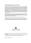
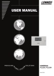
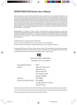
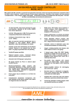
Table of Contents
Certifications……………………………………………………………..
2
Warning and Caution……………………………………………………
3
Installation of Monitor……………………………………………………
4
Using OSD…..…………………………………………………………...
8
Green and P&P………………………………………………………….
10
Trouble shooting…………………………………………………………
10
Appendix A—Specifications…………………………………………….
13
Appendix B—Factory mode……………………………………………
14
Appendix C—Pin assignment………………………………………….
14
Appendix D—Dimension……………………………………………….
14
Notice:
Please read the following words before assembling and using this monitor.
Any reference to an Lenovo product, program or service is not intended to state or
imply that only Lenovo’s product, program, or service may be used. Any functionally
equivalent product, program, or service that does not infringe any of Lenovo’s
intellectual property rights or other legally protectable rights may be used instead of
the Lenovo product, program, or service. Evaluation and verification of operation in
conjunction with other products, programs, or services, except those expressly
designated by Lenovo, are the user’s responsibility.
Lenovo may have patents or pending patent applications covering subject matter in
this document. The furnishing of this document does not give you any license to
these patents.
Information in this document is subject to change without notice.
Without the permission of Lenovo (Beijing) Limited, no part of this manual may be
reproduced or distributed in any form or by any means.
lenovo® is a Lenovo (Beijing) Limited registered trademark.
41CD785-608-4B
1
FCC Class B Radio Frequency Interference Statement
WARNING: (FOR FCC CERTIFIED MODELS)
NOTE: This equipment has been tested and found to comply with the limits for a Class B digital
device, pursuant to Part 15 of the FCC Rules. These limits are designed to provide reasonable
protection against harmful interference in a residential installation. This equipment generates,
uses and can radiate radio frequency energy, and if not installed and used in accordance with
the instructions, may cause harmful interference to radio communications. However, there is no
guarantee that interference will not occur in a particular installation. If this equipment does
cause harmful interference to radio or television reception, which can be determined by turning
the equipment off and on, the user is encouraged to try to correct the interference by one or
more of the following measures:
1. Reorient or relocate the receiving antenna.
2. Increase the separation between the equipment and receiver.
3. Connect the equipment into an outlet on a circuit different from that to which the receiver is
connected.
4. Consult the dealer or an experienced radio/TV technician for help.
2
41CD785-608-4B
Notice:
1.
2.
The changes or modifications not expressly approved by the party responsible for
compliance could void the user's authority to operate the equipment.
The manufacturer is not responsible for any radio or TV interference caused by
unauthorized modification to this equipment. It is the responsibilities of the user to correct
such interference.
WARNING AND CAUTION
1. STOP OPERATING THE MONITOR WHEN YOU SENSE TROUBLE。
Please unplug the monitor immediately if you notice any abnormal phenomena such as
smoke, strange sounds or fumes. Further use may be dangerous and can cause fire or
electric shock.
2. NEVER REMOVE THE CABINET
High voltage inside the monitor, may be electric shocked if removing cabinet.
Non-professor never remove the cabinet.
3. DO NOT PUT ANY OBJECT INTO THE MONITOR。
The ventholes of the monitor is to sink thermal. If blocked or covered, monitor maybe
damage because of overheating. Using the monitor with any object inside may cause fire,
electric shock or damage.
4. DO NOT PLACE THE MONITOR NEAR THE WATER
The monitor maybe damage if water is inside. Do not use the monitor where water may be
splashed or spilt on the monitor as it may cause fire or electric shock.
5. PROTECT YOUR POWER CORD AND SIGNAL CABLE
Do not pull or bend the power cord and signal cable. Do not place the monitor or any other
heavy objects on the cables. If damaged, the cables may cause fire or electric shock.
6. NOTICE THE WEATHER
Do not use monitor immediately if brought it into the warm house from cold environment.
Coagulate bead may cause the monitor short circuit and damage. Before operating the
device, wait until it is absolutely dry.
Unplug the monitor while thunder!
7. PLACE THE MONITOR AT THE RIGHT PLACE
Do not place the monitor near heating source, against a bright background or duct position.
Do not make it near other electronics, such as speaks, TV. There should be more than 50
cm between two monitors. The position should be ventilation, and bright could not reach
the front, side, back of the monitor straight.
41CD785-608-4B
3
8. CLEANING YOUR MONITOR
Do not use alcohol, ammonia based liquid, benzene, or corrosive cleanser to clean the
monitor, they may damage the cabinet or CRT’s surface. You may use soft, clouding cloth
to clean the monitor careful. Notice, you must unplug the monitor before cleaning it.
9. CARING YOUR MONITOR
Unplug the monitor when not use it for a long time. You should take the cables in hands
when lifting the monitor, or you may trip up by them and dropped the monitor.
PACKAGE
There should be the following objects in the package:
1. Monitor
2. Pedestal
3. User Manual
4. Power Cord
INSTALLATION OF MONITOR
PEDESTAL
Unplug the monitor and do like the following steps:
1.
Carefully turn the monitor on its side or upside down.
2.
Locate the cavities at the bottom front of the monitor.
3.
Insert the pegs on the pedestal into these cavities. Push the pedestal forward until the
pedestal locks in place.
4.
To remove the pedestal, hold the bottom of the pedestal, then push it out.
Install
Figure 1.
4
Remove
Installation and Removing of Pedestal
41CD785-608-4B
POWER CORD:
1.
The monitor may work at 100---120VAC or 200---240V AC area. (No user adjustment is
required.)
2.
Connect the power cord into your monitor’s power input socket, and then plug the other
end into a 3-pin AC power outlet.
Connecting the Video Cable: the monitor comes with a built-in video cable. Plug the signal
cable’s 15-pin connector into the computer’s video port and tighten the two screws on the cable
connector. (See figure 2)
Caution: Don’t bend the signal cable, otherwise it will break the inner wire.
Connecting the Power Cord:Plug the power cord into the monitor’s AC power socket. Then
plug the power cord into a grounded AC outlet.
Caution:If the AC outlet is not grounded, install the proper grounding adapter (not supplied).
①
②
Figure 2. Connecting signal cable
1.
Power Cord
2.
Signal Cable
Please keep your user manual, monitor packages on a safety place for further
using.
41CD785-608-4B
5
SETUP
General Instructions
The power switch and other control knobs are located at front panel of the monitor (See Figure
3). Press the power switch to turn the monitor on or off. By changing other control knobs
settings, the picture can be adjusted to your personal preferences.
•
•
•
The power cord should be connected.
Connect the video cable from the monitor to the video card.
To turn the monitor on, press the POWER switch to ON position. The power indicator will
light up.
•
Your monitor features a unique quick switch system which provides a picture within seconds
after the monitor is switched on.
Figure
EXTERNAL CONTROLS
6
1.
Power / Power Indicator
2.
OSD Menu
3.
Contrast
4.
Brightness
5.
Exit
6.
Bright Mode Selection Key
41CD785-608-4B
3
Front Panel Control
•
POWER / Power Indicator: Press this knob to switch ON/OFF of monitor’s power and
display the monitor’s state.
Green
—
Power On mode.
Orange
—
Off mode.
•
MENU : Active OSD menu or function adjust confirm.
•
CONTRAST
•
BRIGHTNESS
•
EXIT : Exit a function or inactive OSD menu, If OSD not shown on the screen, Press this
/
: Adjust contrast or function adjust.
/
: Adjust brightness or function adjust.
knob to display the monitor’s state.
•
BRIGHT MODE SELECTION KEY:Press this key, the menu will be displayed as follows,
OSD bright mode selection menu is shown in Figure 4, and you can select languages in
the LANGUAGE sub-menu to switch between Chinese and English. Under non-OSD,
press bright mode Selection key to set the current brightness mode: the default setting is
Text mode. When this menu is displayed, press bright mode selection key to switch into
Text, Internet and Video modes. In the case of not pressing the MENU, this high bright
mode menu will disappear in 5 seconds automatically.
Text
Internet
Video
Figure 4 English OSD High bright Mode
41CD785-608-4B
7
How to adjust a setting
The
monitor
controls
are
accessed
by
pressing
button
MENU
to
enable
(On-Screen-Display). The main menu will be displayed as follows (see figure 5),
or
1024X768 68K 85Hz
Figure 5 English OSD Message
Adjusting the picture
The description for functional control icons
SIZE & POSITION
:
1.1 HORIZONTAL POSITION
:
Adjust the horizontal position of the picture.
1.2 VERTICAL POSITION
:
Adjust the vertical position of the picture.
1.3 HORIZONTAL SIZE
Adjust the picture’s horizontal size.
:
1.4 VERTICAL SIZE
:
Adjust the picture’s vertical size.
:
1.5 ZOOM
Adjust the picture’s horizontal and vertical size simultaneously.
8
press the
to choose the next window. Choose the English, then press MENU Key for
confirming. OSD window will display in English.
1.
OSD
41CD785-608-4B
2.
GEOMETRY
:
2.1 ROTATION
:
Adjust the picture tilt to horizontal position.
:
2.2 PINCUSHION
Adjust the pincushion and barrel.
:
2.3 BALANCED PINCUSHION
Adjust to compensate the pincushion unbalance.
:
2.4 TRAPEZOID
Adjust the picture’s trapezoid distortion.
:
2.5 PARALLELOGRAM
Adjust the picture to be a rectangle.
:
3.
MOIRE
4.
Moire is the result of interference between the phosphor layout and the video signal.
In some cases, you may find the moire very noticeable. Press the MENU to enter in
the moire reduce setting. Please adjust the level to the optimum condition. Note: Too
high of a setting will cause the picture to shake.
LANGUAGE
:
Select
the language as you like.
5.
OSD TIMER
Choose OSD window display time.
6.
DEGAUSS
If color impurity occurs when moving
degauss to fix the picture condition.
COLOR TEMPERATURE
7.
7.1 6500K/9300K ( COLOR
:
:
or swiveling the monitor, press MENU Key and
:
TEMPERATURE)
The color temperature for 6500K is x=0.313, y=0.329 and 9300K is x=0.283,
y=0.297. It presents two different color sets on the screen. You can select 9300K
or 6500K by pressing MENU Key.
7.2 USER MODE ( Red / Green/ Blue )
If the 9300K normal white or 6500K warmer white do not satisfy your desire,
properly adjust R .G. B GAIN controls to obtain your optimum whiteness level.
8
9.
10.
SUPER BRIGHTNESS QUALITY
Shift the function of Super Brightness Quality
EXIT OSD:
Close OSD window.
:
RESET:
Press RESET to restore the monitor to factory settings.
41CD785-608-4B
9
Green monitor
•
The monitor has a power saving function that conforms to the VESA DPMS standardThis
feature will maximize to decrease power consumption of the monitor.
•
Power saving will be found via indicator:
Mode
On
Off mode
Signal
Attached
Attached
Signal
H-Sync
V-Sync
Yes
Yes
No
No
Video
Active
Blank
Indicator
Green
Orange
Power
Consumption
< 75W
< 2W
PLUG & PLAY
DDC2B feature
This monitor is equipped with VESA DDC2B capabilities according to the VESA DDC
STANDARD. It allows the monitor to inform the host system of its identity and, depending on the
level of DDC used, communicate additional information about its display capabilities.
The DDC2B is a bi-directional data channel based on the I²C protocol. The host can request
EDID information over the DDC2B channel.
TROUBLE SHOOTING
1.No Video / LED Off ( Power Off )
Check monitor is for turning on or turning off.
Check power cord connecting the outlet right.
Check electrical outlet.
Change power cord.
2.No Video / LED On:
If the monitor was on power saving mode and now the indicator(LED) is orange. Please move
mouse and back to normal mode.
Check signal cable connecting the display adapter tightly.
Increase brightness and contrast via OSD.
Check computer is turning on.
The signal cable for bent or broken pins.
10
41CD785-608-4B
3.Poor Focus
Do not place signal cable between monitor and computer.
Verify the current mode is primary mode or not with user manual.
Adjust OSD to decrease the value of item “ moire ”.
Perform degauss.
Decrease brightness and contrast.
Decrease video resolution.
4.Shaky / Jittery Video
Set the computer to primary mode.
Check the signal cable for bent or broken pins.
If connecting UPS, removing UPS and plug monitor to wall outlet.
Away from the speakers, fans, neon lights, fluorescent lights.
5.Color Purity
Perform degauss
Far away from electromagnetic devices. Such as speakers, radios, fans, timers 3 feet away at
least.
Rotate the monitor.
If the color purity spots change position while rotating the monitor, the environment cause the
problem, or the problem is with CRT.
6.Color Convergence
Perform degauss.
Change monitor’s orientation and position.
Active OSD, if it looks like normal. It shows that the monitor need to back to factory and adjust,
or the problem come from video card.
7.Missing Color /Color Flood
It is absence of one of the three basic colors, red, green, blue. The screen is either purple, cyan,
or yellow. If it is absence of two , then the screen is one color last.
Adjust OSD to color temperature 9300K.
Check signal cable for bent or broken pins.
8.Missing Pixels
It shows some dots always dark, bright, or abnormal color what ever the video.
It should be CRT problem / CRT blemish if these dots is on the same position for ever, or
display adapter cause it.
One trio blemish is acceptable for general.
41CD785-608-4B
11
9.Brightness
It indicates too bright or dim.
Adjust brightness.
If OSD has the same problem, it indicates the monitor cause it, or the problem come from
display adapter.
Check signal cable for bent or broken pins.
10.Geometric distortion
Geometric distortion refers to where the shape of the image is distorted in any way, such as
trapezoid, linearity, line straightness, tilt, pincushion, picture size and centering etc.
Check signal cable for bent or broken pins.
Adjust OSD to fix it.
Check the environment, and be far away from the electromagnetic devices.
Rotate monitor.
11.Moire ( Thin Curvy Lines )
Moire is a wavy effect produced by the convergence of lines. A moire pattern is natural optical
effect when converging lines in the picture are
nearly parallel to the scanning lines.
Check signal cable for bent or broken pins.
Increase V_MOIRE value in the OSD.
Adjust picture size to fill the screen to viewing satisfaction.
Note: Some picture could cause moire, and it is difficult to avoid it .
12.Audible Noise
In general, monitor should not make sounds while on. They may make some sounds when
power cycling on or off(degauss cause it).
13.CRT Scratched
Scratched CRT are defined as having the scratch into glass faceplate and where cleaning the
CRT does not remove the scratch.
Power off the monitor you will found them easily.
Note: prevent belt, badges, buttons from scratching the CRT while lifting.
14.Important trouble
If you notice the monitor smoking, sparking, or current leakage, right now unplug the monitor
and take to repair.
12
41CD785-608-4B
APPENDIX A – SPECIFICATIONS
CRT
•
•
Video
Sync.
Synchronization
•
Horizontal
•
Vertical
Max. Resolution
Recommended Res.
Full screen brightness
Small window brightness
Video dot rate
Factory Preset Timings :
User mode Timings :
Power Source
Operating
Humidity
Weight
Signal Cable
Plug & Play
Power management
Power consumption
Preset display area
Regulations
43cm / 17" ( 40cm/16.0” viewing ) High and bright angle of
pure flat surface, 0.25mm dot pitch, non-glare, anti-static,
anti-reflection coating
•
Analog R, G, B 0.7Vpp positive/75 ohm
•
Horizontal sync. : Positive/Negative
•
Vertical sync. : Positive/Negative
30kHz to 69kHz automatically
50Hz to 130Hz automatically
1280 × 1024
1024*768@85Hz
130 cd/m² Max
300 cd/m² Max
110MHz
9
8
Switching mode power supply
AC 100-240V, 50Hz/60Hz full range
0°C to 40°C ambient
10% to 90% relative, non-condensing
15.2kg(Net)
15 pin mini D-Sub
DDC2B
VESA DPMS
Under 75Watts
316mm × 236mm
UL, FCC, MPR II, CCC
41CD785-608-4B
13
APPENDIX B - FACTORY PRESET TIMING TABLE
STANDARD
RESOLUTION
HORIZONTAL
FREQUENCY
VERTICAL
FREQUENCY
Dos-Mode
720 × 400
31.5kHz
70Hz
VGA
640 × 480
31.5kHz
60Hz
VESA/75
640 × 480
37.5kHz
75Hz
VESA/85
640 × 480
43.3kHz
85Hz
VESA/75
800 × 600
46.8kHz
75Hz
VESA/85
800 × 600
53.6kHz
85Hz
VESA/75
1024 × 768
60.0kHz
75Hz
VESA/85
1024 × 768
68.7kHz
85Hz
VESA/60
1280 × 1024
64.0kHz
60Hz
APPENDIX C - Pin Assignment D-SUB
PIN
1
2
3
4
5
6
7
8
INPUT
PIN
RED
GREEN
BLUE
NO CONNECT
GROUND
RED GROUND
GREEN
GROUND
BLUE GROUND
9
10
11
12
13
14
15
APPENDIX D - MONITOR DIMENSION
14
41CD785-608-4B
OUTPUT
NO CONNECT
GROUND
NO CONNECT
DDC SDA
H-SYNC
V-SYNC
DDC CLOCK