1
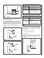
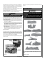
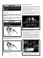
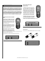
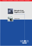
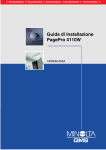
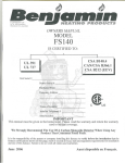
INSTALLATION AND OPERATION INSTRUCTIONS
Vent-Free Millivolt
Dual-Listed Gas Log Sets
Gas Train Models:
LSVFSD-NG
LSVFSD-LP
Log Sets Sold Separately
TM
Log Set Models:
LSVFSD-18 Logs
LSVFSD-24 Logs
LSVFSD-30 Logs
P/N 850051M Rev. C, 03/2011
Installer: Leave This Manual With The Appliance.
Consumer: Retain This Manual For Future Reference.
In the Commonwealth of Massachusetts:
• Installation must be performed by a licensed plumber or gas fitter
• See Table of Contents for location of additional
Commonwealth of Massachusetts requirements
Portland
US
Report No.116-L-49-5
Shadowdance™ Series
WARNINGS
•Hot! Do not touch! This appliance will be hot during operation and will retain heat for a while after
shutting off the appliance. Severe burns may result.
• Carefully supervise children in the same room as appliance.
•Improper installation, adjustment, alteration, service or maintenance can cause injury or property
damage. Refer to this manual. For assistance or additional information consult a qualified installer,
service agency or the gas supplier.
•Do not build a wood fire. Do not burn wood or other material in these appliances.
•Carefully review the instructions supplied with the decorative type unvented room heater for the minimum fireplace size requirement. Do not install the appliance in the fireplace, unless the fireplace meets the minimum
dimensions required for the installations (see Page 3).
•This is an unvented gas log appliance. It uses air (oxygen) from the room in which it is installed. Provisions for adequate
combustion and ventilation air must be provided. Refer to Combustion and Ventilation Air Section on Page 5.
•Important: Read and understand these instructions completely before installing your unvented room heaters.
•This appliance is only for use with the type of gas indicated on the rating plate. This appliance is not convertible
for use with other gases. If the gas supply differs, DO NOT INSTALL the appliance. Contact your dealer to obtain
the correct appliance.
•This appliance may be installed in an aftermarket, permanently located, manufactured (mobile) home, where
not prohibited by local codes.
•Lennox® vent-free gas logs are designed for use as a supplemental heater. They are not intended for continuous use
as a primary heat source.
WARNING: If the information in this manual is not followed exactly, a fire or explosion may result causing property
damage, personal injury or loss of life.
Do not store or use gasoline or other flammable vapors and liquids in the vicinity of this or any other appliance.
WHAT TO DO IF YOU SMELL GAS:
•
•
•
•
Do not light any appliance.
Do not touch any electrical switch; do not use any phone in your building.
Immediately call your gas supplier from a neighbor’s phone. Follow your gas supplier's instructions.
If your gas supplier cannot be reached, call the fire department.
Installation and service must be performed by a qualified installer, service agency or the gas supplier.
IMPORTANT SAFETY AND WARNING
INFORMATION
read THIS MANUAL IN ITS ENTIRETY and understand these Rules to follow for safety.
WARNINGS
If the information in this manual is not followed exactly, a fire or explosion may result
causing property damage, personal injury or
loss of life.
• Children and adults should be alerted to the hazard
of high surface temperature and should stay away to
avoid burns or clothing ignition.
• Do not place clothing or other materials on or near
the heater.
• Young children should be carefully supervised when
they are in the same room with the appliance.
• Due to high temperatures, the appliance should be
located out of traffic and away from furniture and
draperies.
• Any change to this heater or its operating controls can
be dangerous. Improper installation or use of this
appliance can cause serious injury or death from fire,
burns, explosion or carbon monoxide poisoning.
• Carbon Monoxide Poisoning: Early signs of carbon
monoxide poisoning are similar to the flu with headaches, dizziness and/or nausea. If you have these
signs, obtain fresh air immediately. Have the VentFree Gas Heater serviced by a qualified technician
as it may not be operating correctly. Some people
are more affected by carbon monoxide than others.
These include pregnant women, people with heart or
lung disease or anemia, those under the influence of
alcohol, and those at high altitudes.
• Any safety screen or guard removed for servicing an
appliance must be replaced and/or closed prior to
operating the heater.
• Installation and repair should be done by a qualified
service person. The appliance should be inspected
before use and at least annually by a professional service person. More frequent cleaning may be required
due to excessive lint from carpeting, bedding material,
etc. It is important that control compartments, burners
and circulating air passageways of the appliance be
kept clean.
• This appliance is for installation only in a solid-fuel
burning masonry or UL 127 factory-built fireplace or in
a listed ventless firebox enclosure. It has been design
certified for these installations. Exception: DO NOT
install this appliance in a factory-built fireplace that
includes instructions stating it has not been tested
or should not be used with unvented gas logs.
2
WARNINGS
• Allow the appliance to cool before servicing. Always
shut off any electricity or gas to the appliance while
performing service work.
• The appliance and its individual shut-off valve must be
disconnected from the gas supply piping system while
performing any tests of the gas supply piping system at
test pressures equal to or less than 1/2 psig.
• This appliance must not be operated without a fireplace
screen installed. Fireplace screens must not impair
the free flow of combustion air to the appliance.
• Failure to comply with the installation and operation
instructions provided in this document will result in
an improperly installed and operating appliance,
voiding its warranty.
• The appliance must be isolated from the gas supply
piping system by closing its individual manual shut-off
valve during any pressure testing of the gas supply
piping system at test pressures equal to or less than
1/2 psig.
• Keep heater area clear and free from combustible
materials, gasoline and other flammable vapors and
liquids.
• Do not use this room heater if any part has been under
water. Immediately call a qualified service technician
to inspect the room heater and to replace any part of
the control and any gas control which has been under
water.
•Ensure that the appliance is clean when operating.
Excessive dust accumulation on the burner and/or
logs will increase the amount of carbon monoxide
formation and could lead to the formation of soot,
carbon monoxide poisoning and sickness or death.
• Maintain minimum clearances.
• Do not burn solid fuels in any fireplace equipped with
this gas appliance.
• Do not allow fans to blow directly into the fireplace.
Avoid any drafts that alter burner flame patterns.
• Do not install the appliance in a sleeping room or
bathroom.
• The installation must conform with local codes or,
in the absence of local codes, with the National Fuel
gas Code, ANSI Z223.1/NFPA 54-latest edition.
• Input ratings are shown in BTU per hour and are
for elevations up to 4500 feet. When installing any
vent-free appliance at elevations above 4500 feet,
nuisance pilot outages may occur.
• This appliance is intended for supplemental heating.
CONGRATULATIONS!
PACKAGING LIST
When you purchased your new gas log heaters, you joined the
ranks of thousands of individuals whose answer to their home
heating needs reflects their concern for aesthetics, efficiency and
our environment. We extend our continued support to help you
achieve the maximum benefit and enjoyment available from your
new gas log heaters.
Thank you for selecting a Lennox Hearth Products gas log heaters
as the answer to your home heating needs.
The gas train models LSVFSD-NG and LSVFSD-LP are packaged with
the following:
1 -One base/grate assembly
2 -One bag of lava rock
3 - One damper clamp
4 - One literature package, which consists of the installation and
operation manual and warranty
Log sets are sold separately (see Page 15 for ordering information)
INTRODUCTION
These Gas Log Appliances incorporate unitized ceramic fiber logs which
provides some glow realistically when the appliance is operating.
TABLE OF CONTENTS
Important Safety Information..................................................... Page 2
Packaging List............................................................................ Page 3
General Information................................................................... Page 3
Tools Required........................................................................... Page 4
Burn-In Period........................................................................... Page 4
Codes......................................................................................... Page 4
New Your City (MEA) Approval.................................................. Page 5
Requirements for the
Commonwealth of Massachusetts.......................................... Page 5
Combustion and Ventilation Air.................................................. Page 5
Pre installation........................................................................... Page 6
Clearances................................................................................. Page 6
Installation................................................................................. Page 8
Gas Pressure Check................................................................... Page 9
Log Placement Instructions....................................................... Page10
Pilot Flame Appearance.............................................................. Page12
Burner Flame Appearance.......................................................... Page12
Operation and Care.................................................................... Page13
Cleaning and Servicing.............................................................. Page13
Replacement Parts Instructions................................................. Page13
Accessories................................................................................ Page14
Millivolt Wiring Diagram............................................................ Page16
Appliance Specification Chart..................................................... Page16
Operating Instructions – Millivolt............................................... Page17
Troubleshooting Guide............................................................... Page18
Replacement Parts List – Millivolt.............................................. Page19
This installation manual will help you obtain a safe, efficient, dependable installation for your appliance.
PLEASE READ AND UNDERSTAND THESE INSTRUCTIONS
BEFORE BEGINNING YOUR INSTALLATION
The gas log sets covered in this document are heater rated units. These
units are equipped with a millivolt gas valve. The control knob is set to
the desired position, which maintains a continuous gas burning rate.
A spark ignition system (piezo) allows the gas pilot to be lit without the
use of matches or batteries and permits operation of the heater during
a power outage.
GENERAL INFORMATION
These Dual-Listed Gas Log Appliances are equipped with a specially designed
pilot utilizing an oxygen depletion sensor (ODS) which responds to the
amount of oxygen available in the room and shuts the heater off before the
oxygen level drops below 18%. The pilot can be relit only when fresh air is
available. Refer to the Combustion and Ventilation Air section.
These appliances are approved to be installed into an existing masonry
fireplace (built to UBC Chapter 37, Masonry Standards) or factory built
solid fuel, wood burning fireplace (listed to UL 127, Factory Built
Fireplace Standards) or a built-in Vent-Free Firebox (listed to Ventless
Firebox Enclosures for Gas-Fired Unvented Decorative Room Heaters to
ANSI Z21.91). Any outside air ducts and/or ash dumps in the fireplace
shall be permanently closed at time of appliance installation. See
Figure 1 for the minimum size requirements of the existing firebox.
See Figure 1 for the minimum size requirements of the existing firebox
in which the gas logs will be installed.
Log Set
Height
(A)
Depth
(B)
Width Front
(C)
Width Rear
(D)
LSVFSD-18 Logs
19"
14"
30"
20-1/2"
LSVFSD-24 Logs
19"
14"
30"
24-1/2"
LSVFSD-30 Logs
19"
14"
38"
24-1/2"
Top View
Side View
D
B
A
C
Figure 1 - Minimum Fireplace (Firebox) Size
Note: Diagrams AND illustrations ARE not to scale.
3
SEE TABLE 3 ON PAGE 16 FOR BTU INPUT AND GAS PRESSURE
REQUIREMENTS
Do not install these Dual-Listed Gas Log Appliances in a bedroom or
a bathroom as all units exceed maximum allowable BTU/hr input of
10,000.
Tools and Supplies Normally Required
External regulator (Propane models only)
Manual shut-off valve
Sediment trap
Piping complying with local codes
Pipe compound
Pipe wrench
Tee joint
Screwdriver
CODES
Adhere to all local codes or in their absence the latest edition of The
National Fuel Gas Code ANSI Z223.1 or NFPA 54-latest edition which can
be obtained from The American National Standards Institute, Inc. (1430
Broadway, New York, NY, 10018) or National Fire Protection Association,
Inc. (Batterymarch Park, Quincy, MA, 02269).
State or local codes may only allow operation of this appliance in a vented
configuration. Check your state or local codes.
Seller of unvented propane or natural gas-fired supplemental room
heaters shall provide to each purchaser a copy of 527 CMR 30 upon
sale of the unit (This is a standard Unvented Propane or Natural GasFired Space Heaters).
Burn-in Period
Shadowdance™ Gas Log appliances are certified by OMNI-Test Laboratories to ANSI Z21.11.2 unvented room heaters standard. These gas log
appliances may be used as a space heat source for a room in conjunction
with an approved unvented firebox.
During the first few times of operation of this appliance there will be some
odor due to the curing of the paint and burning off of lubricants used
in the manufacturing process. We recommend that you open windows
and ventilate the house during the initial burns. The paint emits non-toxic
odors during this process.
Additionally, these units are design certified by OMNI-Test Laboratories
to ANSI 21.60 / CSA 2.26 Decorative Appliance. For installation in solidfuel burning fireplaces.
Depending on your use, the burn-in period may take a few hours or a few
days. Also if you have a sensitive sense of smell you may notice slight
odors during operating after the burn-in period is over.
KEEP YOUR HOUSE WELL VENTILATED DURING THE BURN-IN PERIOD.
THE ODOR AND HAZE EMITTED DURING THE BURN-IN PERIOD CAN BE
QUITE NOTICEABLE AND MAY SET OFF A SMOKE DETECTOR. MAKE
SURE SMOKE DETECTORS ARE NOT TOO CLOSE TO THE FIREBOX
(CHECK WITH YOUR LOCAL CODE FOR ALLOWABLE DISTANCES).
As such, these units may be used as a vented gas log set in any woodburning fireplace that has been properly constructed to code, and in the
case of factory built fireplaces, installed in compliance with manufacturers
listing and installation instruction.
Use of the log sets covered by this manual in a properly vented woodburning fireplace which has had the damper blocked open as detailed
below, preclude consideration of the combustion and ventilation air and
clearance to combustible restrictions discussed herein.
When local codes require the damper to be fixed open, a damper stop must
be installed to prevent full closure of the fireplace damper and provide a
minimum 29 square inch flue opening at all times.
This appliance is for installation in a solid fuel burning fireplace
(masonry fireplace or manufactured fireplace) with a working flue and
constructed of noncombustible material.
The minimum permanent free opening of the fireplace chimney or
chimney damper must be at least 29 sq. inches based upon a minimum
chimney height of at least 15 feet. Chimney damper must be fixed in
a manner to maintain permanent free opening at all times.
4
New York
Installation of these gas log heaters are approved in the state of New York
and are prohibited in New York City.
Massachusetts Requirements
These fireplaces are approved for installation in the US state of Massachusetts if the following additional requirements are met:
• Unvented Room Heaters shall be installed in accordance with 527
CMR 30.00 and 248 CMR 3.00 through 7.00:
• Installation and repair must be done by a plumber or gas fitter licensed
in the Commonwealth of Massachusetts
• The flexible gas line connector used shall not exceed 36 inches (92
centimeters) in length.
• The individual manual shut-off must be a T-handle type valve.
• Vent-Free appliances may NOT be installed in bedrooms or bathrooms.
• A working smoke detector must be installed in the area where ventfree appliances are installed.
Seller of unvented propane or natural gas-fired supplemental room
heaters shall provide to each purchaser a copy of 527 CMR 30 upon
sale of the unit.
Combustion and Ventilation Air
This heater shall not be installed in a confined space or unusually tight
construction unless provisions are provided for adequate combustion
and ventilation air. The heater may be located in unusually tight construction provided the space is unconfined, or if confined, is provided with two
permanent openings communicating directly with an additional room(s)
of sufficient volume so that the combined volume of all connected spaces
meets the criteria for an unconfined space, (National Fuel Gas Code
NFPA 54 / ANSI Z223.1 (latest edition), Section on Air for Combustion
and Ventilation. Generally 50 ft 3 per 1,000 BTU input of all operating
appliances in the space.
The National Fuel Gas Code, ANSI Z223.1/NFPA 54-latest edition defines
a confined space as a space whose volume is less than 50 cubic feet per
1000 Btu per hour (4.8 m³ per kW) of the aggregate input rating of all
appliances installed in that space and an unconfined space as a space
whose volume is not less than 50 cubic feet per 1000 Btu per hour (4.8
m³ per kW) of the aggregate input rating of all appliances installed in
that space.
Rooms communicating directly with the space in which the appliances
are installed, through openings not furnished with doors, are considered
a part of the unconfined space.
Unusually tight construction is defined as construction where:
a.Wall and ceilings exposed to the outside atmosphere have a continuous water vapor retarder with a rating or one perm (6 x 10-11 kg per
pa-sec-m2) or less with openings gasketed or sealed;
b.Weather stripping has been added on operable windows and doors;
and
c.Caulking or sealants are applied to areas such as joints around window
and door frames, between sole plates and floors, between wall-ceiling
joints, between wall panels, at penetrations for plumbing, electrical,
and gas lines, and at other openings.
Use the following equations to determine if you have a confined or
unconfined space.
1.Determine the volume of space — ft 3.
Length x Width x Height =______ ft 3
(Include adjoining rooms with doorless passageways or ventilation grills
between rooms).
Example: 24' (L) x 16' (W) x 8' (H) = 3072 ft 3
2.Divide the volume of space by 50 ft 3 to determine the maximum BTU/Hr
the space can support.
_(volume of space – ft 3) / 50 ft 3 = (Maximum BTU/Hr the space can
support)
Example: 3072 ft 3 / 50 ft 3 = 61.44
or 61,440 BTU/Hr the space can support.
3.Add the BTU/Hr of all the fuel burning appliances in the space.
Vent-Free Heater
________ BTU/Hr
Gas Appliance #1* ________ BTU/Hr
Gas Appliance #2 +________ BTU/Hr
Total =________ BTU/Hr
Example:
Vent-Free Heater
36,000
Gas Appliance #1
35,000
(water heater)
Total = 71,000
BTU/Hr
BTU/Hr
BTU/Hr
* Do not include Direct-Vent Gas Appliances. Direct-Vent is sealed
combustion and draws combustion air from the outdoors.
5
4.Compare the maximum BTU/Hr the space can support with the actual
amount of BTU/Hr used.
__________ BTU/Hr
(max. the space can support)
__________ BTU/Hr
(actual amount of BTU/Hr used)
Example:
61,440 BTU/Hr
(max. the space can support)
71,000 BTU/Hr
(actual amount of BTU/Hr used)
The space in the above example is a confined space because the actual
BTU/Hr used is more than the maximum BTU/Hr the space can support.
You must provide additional fresh air.
Your options are:
a.Rework equations adding the space of adjoining room(s). If the extra
volume provides an unconfined space, then remove door or add ventilation grills between rooms. Refer to National Fuel Gas Code, ANSI Z223.1
- latest edition, Section on Air for Combustion and Ventilation.
b.Vent room directly to the outdoors. Refer to National Fuel Gas Code,
ANSI Z223.1 - latest edition, Section on Air for Combustion and Ventilation.
c.Install a lower BTU/Hr appliance, such as a 24,000 BTU/Hr, to make
the area an unconfined space.
If the actual BTU/Hr used is less than the maximum BTU/Hr the space
can support, then the space is an unconfined space. You will need no
additional fresh air ventilation for an unconfined space.
WARNING
If the area in which the heater may be operated is smaller
than that defined as an unconfined space or if the building is of unusually tight construction, you must provide
adequate combustion and ventilation air by one of the
methods described in the National Fuel Gas Code, ANSI
Z223.1, Section on Air for Combustion and Ventilation or
applicable local codes.
Preinstallation
WARNING
Before installing in a solid fuel burning fireplace, the
chimney flue and firebox must be cleaned of soot,
creosote, ashes and loose paint by a qualified chimney
cleaner.
CAUTION
Appliances create warm air currents. These currents
move heat to wall surfaces next to appliance. Installing appliance next to vinyl or cloth wall coverings or
operating appliance where impurities in the air (such
as tobacco smoke) exists, may discolor walls.
6
Note: Illustrations shown in this manual reflect “typical” installations
with nominal dimensions and are for reference only. Actual installations
may vary due to individual design preferences. However, always maintain minimum clearances to combustible materials and do not violate
any specific installation requirements. Refer to Figures 2 through 8 for
clearances.
Note: The following steps represent the normal sequence of installation. Each installation is unique, however, and might require a different
sequence.
•
•
•
•
•
•
Turn off gas supply to the fireplace or firebox.
Position appliance in fireplace or firebox.
Connect gas line.
Secure appliance.
Operate the appliance and check operation.
Maintain adequate clearances for accessibility for purposes of servicing
and proper operation.
• Minimum clearances include any projections such as shelves, window
sills, mantels, spacers/standoffs or surfaces to combustible construction etc. above the appliance. Paint or lacquer used to finish the mantel
must be heat resistant in order to avoid discoloration.
Check Gas Type
This appliance can only be connected to the gas type specified on the
appliance rating plate. This appliance can not be modified in the field
for a different gas type. If the gas supply differs, DO NOT INSTALL the
appliance. Contact your dealer to obtain the correct appliance.
Clearances
WARNING
Do not install this gas appliance:
• In sleeping quarters, bathrooms, or a recreational
vehicle.
• Where curtains, furniture, clothing or other flammable
objects are less than 42" from the front of the gas
appliance.
• In high traffic areas.
• In windy or drafty areas.
Vent free applications
WHEN INSTALLED IN A VENT-FREE FIREBOX, IF THE CLEARANCES
SHOWN ON PAGES 7 & 8 OF THIS MANUAL ARE GREATER THAN THE
CLEARANCES FOR THE VENT-FREE FIREBOX, THE LESSER CLEARANCES OF THE VENT-FREE FIREBOX APPLY.
Ensure the minimum clearances shown in Figures 2 through 8 are
maintained. Left and right clearances are determined when facing the
front of the appliance.
Follow these instructions carefully to ensure safe installation. Failure to
follow these requirements may create a fire hazard.
Step 1. Sidewall Clearances: The sides of the fireplace opening must
be at least 16" from any combustible side wall (Figure 2).
Noncombustible Material Requirements with No Mantel Installed
(A) Noncombustible
Material Measurement
42"
Min.
Requirements for Safe Installation
12" or more
Adjustable canopy not required.
8" minimum to 12"
Install adjustable canopy.
Less than 8"
Extend noncombustible material to at least 8" and
install adjustable canopy (Figure 4).
OR
Extend noncombustible material to a height of at
least 12".
16"
Min.
Table 1
Noncombustible Material Heights and Mantel Location
Figure 2 - Clearances
(A) Noncombustible
Material Measurement
Step 2. Ceiling Clearance: The ceiling must be at least 42" from the top
of the appliance opening (Figure 2).
Step 3. Noncombustible materials (minimum requirements): To install
the appliance without wood mantels, shelves or other combustible projections directly above the opening of the fireplace (firebox) refer to Figure
3 and Table 1. Note that at least 8" of noncombustible material must be
installed above the appliances described in this manual.
Noncombustible materials, such as slate and marble, must be at least
1/2" thick.
Noncombustible
Material
Requirements for Safe Installation with Wood
Mantel, Shelf or Other Combustible Projection
12" or more
Adjustable canopy not required. Observe profiles
shown in Figure 5.
8" minimum to 12"
Install adjustable canopy and observe profiles shown
in Figure 4.
or
Extend heat resistant material to at least 12" and
observe profiles shown in Figure 3 and 5.
Table 2
Step 4. Wood mantel, shelf or combustible projection requirements:
To install a wood mantel, shelf or other combustible projection directly
above the fireplace (firebox), refer to Table 2 and to Figures 5 and 6 for
installation profiles.
If your mantel profile is unsafe, you may either:
A
•Raise the mantel to an acceptable height, or
•Remove the mantel.
Appliance in
Fireplace or
Firebox
Example: The bottom of the mantel may project from the wall a maximum
of 2-1/2" at a minimum of 28" above the opening. The top shelf of the
mantel may project a maximum of 6" at a minimum of 34-1/2" above
the opening.
Figure 3
10"
8"
6"
Ceiling
42"
2-1/2"
8" or More of
Noncombustible
Material
38-5/8"
34-1/2"
Adjustable
Canopy
28"
Noncombustible
Material
12"
Appliance in
Fireplace or
Firebox
Figure 4
Figure 5
Note: Diagrams AND illustrations ARE not to scale.
7
Example: The bottom of the mantel may project from the wall a maximum of 2-1/2" at a minimum of 8" above the opening. The top shelf of
the mantel may project a maximum of 6" at a minimum of 14-1/2" above
the opening.
12"
10"
8"
6"
26"
22-1/2"
2-1/2"
18-5/8”
8"
Min.
14-1/2"
Hood (Canopy)
Noncombustible
Material
Installation
WARNINGS
• Do not use a blower insert, heat exchanger
insert or other accessor y not approved
for use with this heater.
• Installed decorative glass door enclosures must be
fully opened when operating this dual-listed gas
appliance.
• Special care is required if you are installing the unit
into a sunken fireplace. You must raise the fireplace
floor to allow access to gas log controls. This will
ensure adequate air flow and guard against sooting. Raise the fireplace floor using noncombustible
materials.
Any outside air ducts and/or ash dumps in the fireplace shall be permanently closed at time of appliance installation.
A qualified gas appliance installer must install this dual-listed appliance.
Figure 6
Step 5. Floor clearance: If combustible flooring materials, such as carpeting or asphalt tile, are to be located within 14" of the fireplace or firebox
opening, the appliance base must be at least 5" above the combustible
flooring material (Figure 7).
Check gas type: The gas supply must be the same as stated on the
appliance’s rating plate. If the gas supply is different, DO NOT INSTALL
the appliance. Contact your dealer for the correct model.
Step 1. Unpack Appliance - Remove appliance from carton. Cut tie-wires
holding ember bed rear log to the base. Unwrap foam packaging from
ember bed rear log.
Step 2. Placement of Appliance – Center the appliance in the fireplace
or firebox. Make certain the grate front feet sit inside the front edge of
the fireplace or firebox, and that there is adequate clearance around the
appliance for access and operation.
Step 3. Connecting Gas Line – A qualified gas appliance installer must
connect the dual-listed gas appliance to the gas supply.
Combustible Flooring
Material
5" Min.
Figure 7
Step 5. Place Logs – See log placement on Page 10.
The appliance base may be lower than 5" above the combustible flooring
materials if the combustible flooring materials are more than 14" from the
fireplace or firebox opening (Figure 8).
Can be less
than 5"
Combustible
Flooring
Material
14" Min.
Figure 8
8
Step 4. Place Ember Bed Rear Log – Place the ember bed rear log with
ember chunks facing the front of the appliance such that the middle grate
bar aligns with the notch in the top of the ember piece. Push the ember
bed rear log toward the front of the unit until it touches the lip on the
base and cannot go any further.
Note: Diagrams AND illustrations ARE not to scale.
Consult all local codes.
Route gas line using techniques and materials prescribed by local
and/or national codes. Only use 1/2" or greater pipe size to allow full gas
volume to the gas fireplace. Undue pressure loss will occur if the pipe
is too small.
An ANSI approved manual shut-off valve and union must be installed upstream
of the appliance within the fireplace cavity when rigid pipe is used.
Important: Hold appliance regulator with a wrench to
prevent movement when connecting to inlet piping
An external regulator must be used on all propane (L.P.G.) appliances,
in addition to the regulator fitted to the appliance, to reduce the supply
tank pressure to 13" W.C. (maximum).
WARNING
Connecting directly to an unregulated propane tank may
cause an explosion.
The appliance gas inlet connection is 3/8" NPT at the regulator/valve,
located on the left side facing the appliance. If a right side connection is
required, the connection pipe may be piped under the rear of the appliance
to end at the left hand side for connection to the inlet.
When tightening up the joint to the regulator hold the regulator securely
with a wrench to prevent the regulator from moving.
Replace the test point plug after pressure measurement ensuring no
gas leaks.
Step 4. PLACING THE LOGS
Checking Gas Connections: Test all gas joints from the gas meter to the
gas appliance regulator for leaks after completing connection.
WARNING
Never use an open flame to check for leaks.
Turn on gas supply and test for gas leaks using a gas leak test solution (also
referred to as bubble leak solution). Note: Using a soapy water solution
(50% dish soap, 50% water) is an effective leak test solution but it is not
recommended, because the soap residue that is left on the pipes/fittings can
result in corrosion over time.
WARNINGS
Do not add extra logs or ornaments such as pine cones,
vermiculite or rock wool. Using these added items can
cause sooting.
Do not place any lava rock on logs or burners. This
may cause sooting. Only place lava rock on floor of
fireplace.
A.Light the appliance (refer to the lighting instructions label attached to the
control valve or see Page 17).
B. Brush all joints and connections with the gas leak test solution to check for
leaks. If bubbles are formed, or gas odor is detected, turn the gas control
knob (off/pilot/on) to the “OFF” position. Either tighten or refasten the
leaking connection, then retest as described above.
C.When the gas lines are tested and leak free be sure to rinse off the
leak testing solution.
D. Turn on burner then observe the individual tongues of flame on the burner.
Make sure all ports are open and producing flame evenly across the burner.
If any ports are blocked, or partially blocked, clean out the ports.
Rear Log
Rear Ember Bed
Gas Pressure Check
The appliance regulator controls the burner pressure which should be
checked at the pressure test point (1/8" NPT plugged tap) located on the
millivolt control valve itself, identified OUT for the manifold side and IN
for inlet pressure (see Figure 9). Ensure operating pressures are within
the limits specified in the technical chart on Page 16.
Left Top Log
The pressure should be checked with the gas appliance burning and the
control set to high.
Right / Front
of Appliance
*
Figure 9
Middle Log
Center Top Log
Left Front Log
Right Front Log
Piezo Igniter
Left / Front
of Appliance
Gas Valve
Left Top Twig
On/Off
Rocker Switch
Pilot/On/Off Knob
Flame Height Knob
Right Top Log
Front Ember Bed
*
The twig indicated is included in the 24" and 30" log sets only.
• The 30" log set also includes 2 ember chunks (shown in Figure
18b)
Figure 10 - Log Set
Note: Diagrams AND illustrations ARE not to scale.
9
Log Placement Instructions
1.Place rear ember bed as shown in Figure 11.
Top Burner
Locating
Pins
Rear Ember Bed
Install
Ember bed
from behind
top burner
4.Place left and right front logs onto front grate locating pins as
shown in Figure 14.
Right Front Log
Left Front Log
Position Ember Bed All the Way
Forward in Gas Train Assembly
Locating Pins Indicated by Arrows
Figure 14 - Install Left and Right Front Logs
Figure 11 - Install Rear Ember Bed
2.Place rear log onto the two rear grate locating pins as shown
in Figure 12 (the locating pins are outlined in Figure 11).
Rear Log
5.Place left top log onto rear log and middle log locating pins as
shown in Figure 15.
Left Top Log
Locating Pins
Rear Locating Pins
On Grate Assembly
Figure 15 - Install Left Top Log
Figure 12 - Install Rear Log
3.Place middle log onto left middle grate locating pin and the rear
ember bed locating pin as shown in Figure 13.
6.Place the center top log onto the rear log locating pin and middle
log locating pin as shown in Figure 16.
Center Top Log
Middle Log
Locating Pins
Locating Pins
Figure 13 - Install Middle Log
10
Figure 16 - Install Top Center Log
Note: Diagrams AND illustrations ARE not to scale.
7.Place the right top log onto rear log locating pin and the right
front log locating pin as shown in Figure 17.
9.Place the front ember bed log as shown in Figures 18A and
18B.
Right Top Log
18" Gas Log Set
Locating Pins
Figure 17 - Install Right Top Log
24" Gas Log Set
8.Place Left Top Twig (24" and 30" models only) onto corresponding
notch on rear log as shown in Figure 18A. The front of the Left
Top Twig should be up against and behind the left top log.
Left Top Twig
Left Top Log
30" Gas Log Set
Front Ember Bed
Figure 18A - Install Left Top Twig
Figure 18B - Completed Installation
Note: Diagrams AND illustrations ARE not to scale.
11
WARNING
Failure to position the parts in accordance with Figure
21 or failure to use only parts specifically approved
with this appliance may result in property damage or
personal injury.
Periodically check the positioning of all logs.
Flame Appearance
Refer to the operating instructions located at the back
of this manual before lighting the appliance to observe
the flames.
Burner And Flame Characteristics
The Shadowdance™ Gas Log Set features a new concept in integrated
burner and log design. The flames from the burner travel horizontally
through the log set and emerge at the knot holes.
The flames are slightly blue off the burner and as they progress through
the log set, they change to a light yellow color. Yellow decorative flames
are visible as the flames exit the log set.
When the log set is first lit, the flame may be entirely blue. Light yellow
flame will form at the top of the logs after several minutes of operation.
The base of the log set and the underside of the top log glows a brilliant
red. For an example of the log set, see Figure 21.
Flames from the pilot burner should be visually checked as soon as the
appliance is installed. In addition a periodic visual check of the flames
should be made. The pilot flame should always be present when the
appliance is in operation (Figure 19).
WARNING
No adjustments are to be made to the ODS
pilot system. Tampering with this system can
be extremely hazardous.
Propane Pilot Shown
Figure 21 - Proper Burner Flame Appearance
Top Burner Air Shutter Adjustment Procedure
Figure 19 - Correct Pilot Flame
An incorrect pilot flame pattern is shown in Figure 20. This pilot flame
will cause the thermocouple to cool. When the thermocouple cools, the
log set will shut off. If pilot flame pattern is incorrect, or if log set shuts
off, contact your service technician.
1.If you have blue flame or the top burner is not carrying over and burning
on all ports, the air shutter may need to be adjusted to 1/8" gap for
both Natural and Propane gas.
2.Check to see if the air shutter is set to 1/8" opening (see Figure 22).
The air shutter is located on the rear left side of the appliance.
3.If the air shutter opening is more than 1/8" please loosen the air shutter
screw and close completely which will set it to the 1/8" opening.
Note: In some instances, propane appliances may need to be adjusted
from the standard factory setting. DO NOT open the air shutter greater
than 1/4".
Propane Pilot Shown
Figure 20 - Incorrect Pilot Flame
In normal operation, at full rate, after 15 minutes the following flame
appearance should be observed:
Using a 1/4" wrench loosen setscrew and adjust air shutter to 1/8" gap
Figure 22 - Top Burner Air Shutter Gap - 1/8" for NG & LP
12
Note: Diagrams AND illustrations ARE not to scale.
Operation and Care of your appliance
1.Appliance operation may be controlled through the ON/OFF unit
rocker switch, located in the bottom front of the appliance or through
an optional remote control.
2. When lit for the first time, the appliance will emit an odor for an hour
or two. This is due to the “burn-in” of the internal paints and lubricants
used in the manufacturing process. For the first few hours, operate the
appliance with doors and windows open to encourage the dissipation
of odor.
Cleaning and Servicing
WARNING
Only limited cleaning will be required under the normal use of the appliance. Dust the front grate, the top of the piezo cover and the control knob
occasionally. Do not use cleaning fluids to clean the logs or any other
part of the appliance.
Remove the log set, gently handling at each end. Use a vacuum cleaner to
remove loose particles from the base and from around the burners. Gloves
are recommended to prevent the fibers from pricking your skin. If the skin
is pricked, wash gently with soap and water. Replace the log set.
If, after a period of use, the flames start to exhibit unusual shapes and
behavior, if there is any evidence of soot formation, blue tipping of the
flames, or any strong odors, or the burners fail to ignite smoothly, then
the burner holes may require some cleaning. If this happens, it is preferable to contact your nearest authorized service technician to get the
appliance serviced.
Turn off the appliance and allow to cool before cleaning.
Verify proper operation after servicing.
WARNING
You must keep control areas, burners and circulating air
passageways of appliance clean. Failure to keep the
primary air opening(s) of the burner(s) clear may result
in sooting and property damage. Inspect these areas of
appliance before each use. Have appliance inspected
yearly by a qualified service person. Appliance may
need more frequent cleaning due to excessive lint form
carpeting, bedding material, etc.
Note: Diagrams AND illustrations ARE not to scale.
13
Deluxe Remote Control System
(Model RC-STAT)
Accessory Components
All options are available in kit form, are easy to install and are packaged complete with all required parts and instructions. Some of the
option kits need to be fitted prior to completing the installation of the
appliance. The following paragraphs detail the kit options available.
The appliances covered in this manual are heater rated and produce a
great deal of heat. Decorative brass trim pieces and hoods may tarnish
because of their proximity to the heater opening and front face. Tarnishing of these pieces is normal, unavoidable and should be expected.
The Model RCL-T (Deluxe) Remote Control System
has all of the features of the standard system
along with an added easy to read LCD screen
which presents access to many enhancements,
including; battery power level indicator, timer,
mode of operation, thermostatic display including
room temperature in either metric of English units,
flame indicator and clock. Fully programmable,
the Model RCL-T allows for virtual command over
nearly all operational and temperature variables,
using the hand held remote control transmitter.
The Model RCL-T (Deluxe) remote control system
is installed in the same manner as the standard
system, may be operated with electronic and millivolt systems with either natural or propane gas.
The RCL-T comes complete with detailed operating instructions.
Standard Remote Control System (Model
RCL)
The Model RCL (Standard) Remote Control
System, features a simplistic on/off control
function for the fireplace. This model includes
a hand-held transmitter, a remote receiver with
wall-mount cover plate and all hardware required
to install the unit. The remote receiver can be
wall or hearth mounted.
Remote Control System - Deluxe
The transmitter has ON and OFF functions that are
activated by pressing either button on the face of
the transmitter. When a button on the transmitter
is pressed, a signal light illuminates briefly to
verify that a signal has been sent.
Cat. No.
Model No.
Description
H0251
RCL-T
Remote Control Kit - Deluxe
(ref form #750129M)
The Model RCL is designed to operate with all
millivolt ignition systems, as well as electronic
ignition systems. It may be installed with use for
either natural or propane gas appliances. The RCL
offers ease of installation and allows you to execute on-off commands to the log
set effortlessly with one simple motion.
Knob Extensions
Knob extensions for both the On/Off and High/Low functions are available.
The Model RCL comes complete with detailed operating instructions.
Remote Control System - Standard
Cat. No.
Model No.
Description
H0249
RCL
Remote Control Kit - Standard
(ref form #750127M)
Knob Extensions
14
Cat. No.
Description
60J74
Knob Extension, Pilot/On/Off
60J95
Knob Extension, Hi/Lo
Note: Diagrams AND illustrations ARE not to scale.
Charred Ember Kit
Accessory Components (continued)
An optional 2-piece Charred Ember Kit is available to enhance the beauty of the
log set.
Gas Log Sets
Left Charred Ember
18" Gas Log Set
Right Charred Ember
Charred Ember Kit*
Cat. No.
Model No.
Description
H6894
LSVFSD-CEK
Charred Ember Kit
(ref form #750252M)
* This kit is standard with the 30" Log Set
24" Gas Log Set
Shadowdance Burner Assemblies
Cat. No.
Model No.
Description
H8304
LSVFSD-NG
Shadowdance NG Burner
H8305
LSVFSD-LP
Shadowdance LP Burner
30" Gas Log Set
Bag of Volcanic Stone
Gas Log Sets*
Cat. No.
Model No.
Description
H5137
LSVFSD-18 Logs
Shadowdance™ 18" Logs
H5138
LSVFSD-24 Logs
Shadowdance 24" Logs
H5139
LSVFSD-30 Logs
Shadowdance 30" Logs
* For use with gas train models LSVFSD-NG and LSVFSD-LP only
Volcanic stone is available for use with
these appliances.
Decorative Volcanic Stone
Cat. No.
Model No.
Description
80L42
FDVS
Bag of Volcanic Stone
(ref form #750010M)
Note: Diagrams AND illustrations ARE not to scale.
15
CAUTION: Label all wires prior to disconnection when servicing controls.
Wiring errors can cause improper and dangerous operation.
THERMOPILE
PILOT (O.D.S.)
ASSEMBLY
If any of the original wire as supplied must be replaced, it must be replaced
with Type AWM 105°C – 18 GA. wire.
MILLIVOLT VALVE
WHITE
RED
OPTIONAL
REMOTE CONTROL
(MILLIVOLT)
IGNITION
WIRE
ON
ON/OFF
SWITCH
OFF
WHITE
WHITE
PILOT PIEZO
IGNITER
Figure 23 - Millivolt Wiring Diagram
Vented/Unvented Gas Log Appliance Technical Chart For Millivolt Log Set
Model No.
BTU/HR
Input
Gas Type
LSVFSD-NG
37,000
24,500
Natural
LSVFSD-LP
37,000
28,000
Propane/
LPG
Table 3
16
Ignition
Regulator
Pressure Setting
Gas Inlet
Pressure*
Valve
Orifice Size Orifice Size
Operation
Top
Bottom
Piezo
1.6 – 3.5" W.C.
Max. 10.5" W.C.
Min. 5.0" W.C.
Millivolt
.094"
.071"
1/8"
Piezo
6.3 – 10.0" W.C.
Max. 13" W.C.
Min. 11" W.C.
Millivolt
.055"
.046"
1/8"
* For the purpose of input adjustment.
Note: Diagrams AND illustrations ARE not to scale.
Air Shutter
Opening
Lighting Instructions – Millivolt
FOR YOUR SAFETY READ BEFORE LIGHTING
WARNING: IF YOU DO NOT FOLLOW THESE INSTRUCTIONS EXACTLY, A FIRE OR EXPLOSION
MAY RESULT CAUSING PROPERTY DAMAGE, PERSONAL INJURY OR LOSS OF LIFE.
A.This appliance has a pilot which must be lighted with a piezo
igniter. When lighting the pilot, follow these instructions
exactly.
WHAT TO DO IF YOU SMELL GAS
• Immediately call your gas supplier from a neighbor’s phone.
Follow the gas supplier's instructions.
• If you cannot reach your gas supplier, call the fire department.
C.Use only your hand to push in or turn the gas control knob.
Never use tools. If the knob will not push in or turn by hand,
don't try to repair it, call a qualified service technician. Force
or attempted repair may result in a fire or explosion.
• Do not try to light any appliance.
• Do not touch any electrical switch; do not use any phone in
your building.
D. Do not use this appliance if any part has been under water.
Immediately call a qualified service technician to inspect the
appliance and to replace any part of the control system and
any gas control which has been under water.
B. BEFORE LIGHTING smell all around the appliance area for gas.
Be sure to smell next to the floor because some gas is heavier
than air and will settle on the floor.
LIGHTING INSTRUCTIONS
1. STOP! Read the safety information above on this page.
2.Access the lower control compartment.
7. Push in gas control knob slightly and turn counterclockwise
to “PILOT.”
3.Turn remote wall switch to “OFF.”
4. Verify main line shut-off valve is open.
5. Push in gas control knob slightly and turn clockwise
to “OFF.”
IN
OUT
TPTH
TP
8. Push in control knob all the way and hold in. Immediately
light the pilot by triggering the spark igniter (pushing the
button) until pilot lights. Continue to hold the control knob
in for about 1-1/2 minutes after the pilot is lit. Release knob
and it will pop back up. Pilot should remain lit. If it goes out,
repeat steps 5 through 8.
•If knob does not pop up when released,
stop and immediately call your service
technician or gas supplier.
O FF
it
P IL O T
TH
ON
•If pilot will not stay lit after several tries,
turn the control knob to “OFF” and call
your service technician or gas supplier.
P IL
OT
6. Wait five (5) minutes to clear out any gas. If you then smell
gas, STOP! Follow “B” in the safety information above on
this page. If you do not smell gas, go to the next step.
Note: Knob cannot be turned from “PILOT” to “OFF”
unless the knob is pushed in slightly. Do not force.
9.Turn gas control knob counterclockwise
to “ON.”
10.Close lower control compartment.
TO TURN OFF GAS TO APPLIANCE
1.Turn remote wall switch “OFF.” The pilot will remain lit for
normal service.
4. Depress gas control knob slightly and turn clockwise
to “OFF.” Do not force.
2. For complete shutdown, turn remote wall switch to “OFF.”
5.Close lower control compartment.
3.Access the lower control compartment.
17
Vented/Unvented Troubleshooting Guide
Observed Problem
Remedy
A.Igniter electrode positioned wrong.
Replace igniter.
B.Igniter electrode broken.
Replace igniter.
C.Igniter electrode not connected to igniter cable.
Reconnect igniter cable.
D.Igniter cable pinched or wet.
Free igniter cable if pinched by any metal or tubing. Keep igniter cable dry.
E. Piezo igniter nut is loose.
Tighten nut.
F. Broken igniter cable.
Replace igniter cable.
G.Bad piezo igniter.
Replace piezo igniter.
2. Heater produces unwanted
odors.
A. Heater burning vapors from paint, hair spray, glues, etc.
Ventilate room. Stop using odor-causing products while fireplace is running.
B.Gas leak. See Warning statement on the front page.
Locate and correct all leaks.
3. Heater shuts off in use (ODS
operates).
A. Not enough fresh air is available.
Open window and/or door for ventilation.
B.Low line pressure.
Contact local gas company.
C.ODS/pilot is partially clogged.
Clean ODS/pilot.
4.Gas odor even when control
knob is in “OFF” position.
A.Gas leak. See Warning statement on the front page.
Locate and correct all leaks (see Checking Gas Connections, Page 9).
B.Control valve defective.
Replace control valve.
5. When igniter button is
pressed, there is spark at
ODS/pilot, but no ignition.
A.Gas supply turned off or manual shut-off valve closed.
Turn on gas supply or open manual shut-off valve.
B.Control knob not in “PILOT” position.
Turn control knob to pilot position.
C.Control knob not pressed in while in “PILOT” position.
Press in control knob while in pilot position.
D.Air in gas lines when installed.
Continue holding down control knob. Repeat igniting operation until air is removed.
E.ODS/pilot is clogged.
Replace ODS/pilot assembly or get it serviced.
1. When igniter button is
pressed, there is no spark
at ODS/pilot.
6.ODS/pilot lights, but flame
goes out when control knob is
released.
F.Gas regulator setting is not correct.
Replace gas regulator.
A.Control knob not fully pressed in.
Press in control knob fully.
B.Control knob not pressed in long enough.
After ODS/pilot lights, keep control knob pressed in 30 seconds.
C.Manual shut-off valve not fully open.
Fully open manual shut-off valve.
D.Thermocouple connection loose at control valve.
Hand tighten until snug, then tighten 1/4 turn more.
E. Pilot flame not touching thermocouple, which allows
thermocouple to cool, causing pilot flame to go out. This
problem could be caused by one or both of the following:
1). Low gas pressure
2). Dirty or partially clogged ODS/pilot
1). Contact local gas company.
2). Replace ODS/pilot assembly or get pilot serviced.
F.Thermocouple damaged.
Replace thermocouple.
G.Control valve damaged.
Replace control valve.
A. Burner orifice is clogged.
Clean burner or replace burner orifice.
B. Burner orifice diameter is too small.
Replace burner orifice.
C.Inlet gas pressure is too low.
Contact local gas company.
A.Manifold pressure is too low.
Contact local gas company.
B. Burner orifice is clogged.
Clean burner or replace burner orifice.
A. Burner orifice is clogged or damaged.
Clean burner or replace burner orifice.
B. Burner damaged.
Replace burner.
C.Gas regulator defective.
Replace gas regulator.
10.Slight smoke or odor during
initial operation.
A. Vapors from paint or curing process of logs.
Problem will stop after a few hours of operation. Superior recommends running the
heater with the excess ventilation for the first few hours.
11. Heater produces a whistling
noise when burner is lit.
A.Turning control knob to “HI” position when burner is
cold.
Turn control knob to “LO” position and let warm up for a minute.
B.Air in gas line.
Operate burner until air is removed from line. Have gas line checked by local gas
company.
C. Dirty or partially clogged burner orifice.
Clean burner or replace burner orifice.
7. Burner does not light after
ODS/pilot is lit.
8. Delayed ignition of burner.
9. Burner backfiring during
combustion.
18
Possible Cause
12. The flame appearance is blue.
A. Improper Air Shutter Adjustment.
Adjust air shutter per instructions on Page 12.
13. When burner lights, flame
does not carry completely
across the top burner.
B. Improper Air Shutter Adjustment.
Adjust air shutter per instructions on Page 12.
Replacement Parts List (Millivolt) - Shadowdance™ series
Replacement Parts List (Millivolt) - Shadowdance™ Series, Models LSVFSD-NG and LSVFSD-LP (18" and 24")
No.
Description
1.
Catalog Number
Valve, Millivolt (Natural)
H1203
Valve, Millivolt (Propane, L.P.G.)
H4278
2.
Ember Bed Front
H3910
3.
Ember Bed Rear
H3911
4.
Bottom Burner
H3912
5.
Top Burner
H3913
6.
Piezo Igniter
10K86
7.
ODS Pilot Assembly, Millivolt (Natural)
H4113
8.
ODS Pilot Assembly, Millivolt (Propane, L.P.G.)
H4170
9.
Knob Extension, Pilot/On/Off
60J74
10.
Knob Extension, Hi/Lo
60J95
11.
On/Off Switch
27K30
12.
Piezo Igniter Cable
H4868
13
18" Log Assembly
H5137
14
24" Log Assembly
H5138
15
30" Log Assembly
H5139
14
13
NG Pilot
Assembly
10
7
18" Gas Log Set
1
24" Gas Log Set
4
5
15
11
6
30" Gas Log Set
6
10
9
WARNING
Failure to position the parts in accordance with these
diagrams or failure to use only parts specifically
approved with this heater may result in property
damage or personal injury.
Top View
Note: Diagrams AND illustrations ARE not to scale.
19
Warranty
Your gas appliance is covered by a limited warranty (provided with
appliance). Please read the warranty to be familiar with its coverage.
Retain this manual. File it with your other documents for future reference.
Product reference information
We recommend that you record the following important information
about your appliance. Please contact your Lennox Hearth Products dealer
for any questions or concerns. For the number of your nearest Lennox
Hearth Products dealer, please call 1-800-9-LENNOX.
Replacement parts
See Page 19 for a complete replacement parts list. Use only parts supplied from the manufacturer.
Normally, all parts should be ordered through your Lennox Hearth
Products distributor or dealer. Parts will be shipped at prevailing prices
at time of order.
When ordering repair parts, always give the following information:
1. The model number of the appliance.
2. The serial number of the appliance.
3. The part number.
4. The description of the part.
5. The quantity required.
6. The installation date of the appliance.
If you encounter any problems or have any questions concerning the
installation or application of this system, please contact your dealer.
LENNOX HEARTH PRODUCTS
1508 Elm Hill Pike, Suite 108
Nashville, TN 37210
Visit us at www.Lennox.com
Your Appliance's Model Number________________________________________
Your Appliance's Serial Number_________________________________________
The Date On Which Your Appliance Was Installed___________________________
The Type of Gas Your Gas Appliance Uses_________________________________
Your Dealer's Name__________________________________________________
Fuel Type (Check one)
c
Natural Gas
c
Propane Gas (LP)
Lennox Hearth Products reserves the right to make changes at any time, without notice, in
design, materials, specifications, prices and also to discontinue colors, styles and products.
Consult your local distributor for fireplace code information.
Printed in U.S.A. © 2007 by Lennox Hearth Products
20
P/N 850051M REV. C 03/2011
1508 Elm Hill Pike, Suite 108 • Nashville, TN 37210