1
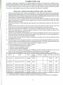
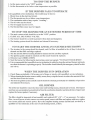
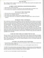
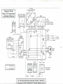
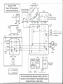
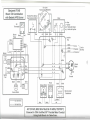
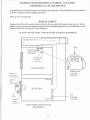
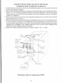
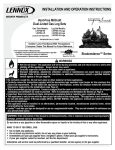
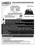
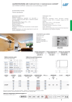
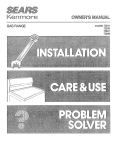
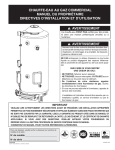
A DIVISION OF
V/.R. BENJAMIN
PRODUCTS LIMITED
HEATING PRODUCTS
OWNERS MANUAL
MODEL
FS140
IS CERTIFIED TO:
1
CSA B140.4
CAN/CSA B366.1
CSA B212 (EEV)
UL391
UL727
Unit Serial #
Burner Serial #
Purchased From
Company Address
Name of Installer
Installer Telephone #
Date Installed
IMPORTANT
This manual must be given to the homeowner. Please read the warranty and return the warranty
card to initiate coverage.
We Strongly Recommend The Use Of A Carbon Monoxide Detector When Using Any
Product That Consumes Fossil Fuels.
It is the responsibility of the person or company installing this furnace to verify before the installation that the
furnace certifications shown on this page, meet or exceed all local, state and regulatory requirements for installation
and use of this furnace. Failure to do so voids all claims and warranties.
June 2006
Aussi disponible en Francais.
KEEP THIS MANUAL FOR FUTURE REFERENCE. Follow all the Instructions carefully for
installation, maintenance & operation of the Benjamin Fuel Saver Combination Hot Air
THE FURNACE IS SHIPPED IN TWO PACKAGES
Note: The consignee is responsible for ensuring that the packages have arrived in good condition.
Examine packages for damages, if found, note the same on carriers' bill of lading and make a
claim to the carrier. Each unit is carefully inspected before leaving our factory.
Package no. 1
Package no. 2
The furnace, blower, blower motor, pulleys, belt (assembled), air filter & cleaning
hoe.
1-oil burner, 1-nozzle, 1-damper motor, 2-thermostats(wood & oil).The primary
harness is prewired to the oil burner and consists of 1-fan limit, 1-blocked flue
sensor, 1-transformer,
1-relay, 1-J box and cover.
INSTALLATION
The installation of this equipment shall be in accordance with: In Canada, CSA Standard B139
"Installation Code for Oil Burning Equipment" and CSA B365 Installation Code for Solid Fuel
Burning Appliances and Equipment. In the United States, UL 391 Solid Fuel and Combination Fuel
Central and supplementary furnaces. Electrical and mechanical installations must conform to all local
and national codes and standards as their jurisdiction may apply. Ensure to have a minimum of 200
sq. inches of return air.
CHIMNEY AND SMOKE PIPE
The specification of the chimney to be used, must comply with the requirement that, other than solidfuel/oil combinations and add-ons, wood burning appliances shall not be connected to a venting system
serving an appliance vented by another type of fuel. Connect the furnace to an approved solid fuel
factory-built chimney: in CANADA-CAN/ULC S629 standard for 650° chimney, in the UNITED
STATES-UL103 Chimneys for Residential Type and Building Heating Appliances, Factory Built or a
safe, clean, sound condition, masonry chimney equipped with an approved liner: in CANADACAN/ULC-S635-M90 Standard for Lining Systems for existing masonry or Factory Built Chimneys and
Vents, in the UNITED STATES-UL1777 Chimney Liners (e.g., stainless steel, clay, etc.). The chimney
must be equivalent to a minimum of 7" round inside diameter or 8" round maximum. The chimney
must be capable of maintaining a negative updraft at all times and in all conditions. Carefully inspect
the chimney for safety and dirt before making connections. Place the furnace as close to the chimney
as possible.
The smoke pipe should be blue or black steel, 24 ga. or heavier. Use as few turns as possible between
the furnace and the chimney, as each 90° elbow adds 10' of restriction and a 45° elbow adds 5' of
restriction. The barometric damper should be 7" diameter and set at -.04 W.C. to open. Install the
barometric damper a minimum of 18" and a maximum of 24" from the furnace breech. Avoid long
horizontal runs of smoke pipe. Maintain a minimum of Yt" rise per foot of pipe from the furnace to the
chimney.
DO NOT run the pipe downhill from the furnace to the chimney. Confirm that the installation
clearances are met or exceeded. All pipe joints should fit relatively gas tight. Secure all smoke pipe
joints with three sheet metal screws in each joint.
DO NOT pass the smoke pipes through a wall, floor or ceiling to reach the chimney. Remove the
smoke pipe from the furnace and clean monthly or as necessary.
CAUTION: USE ONLY METAL DUCTS FOR THIS FURNACE.
-1-
COMBUSTION AIR
To achieve satisfactory combustion, an adequate supply of fresh air is required. In confined areas, a
grilled opening shall be provided. The minimum total area of openings is 2 square feet per gallon (.60m
per 4.5L) of oil burnt per hour. Where fans are used in the fuel storage area, they should be installed
so as not to create negative pressures in the room where the furnace is installed.
INSTALLATION INSTRUCTIONS (OIL SECTION)
1.
2.
3.
4.
5.
6.
7.
8.
9.
10.
11.
12.
13.
Mount the blocked flue sensor "Field Controls WMO-1" on the upper-left of the burner mounting plate
using the nuts provided with the sensor. Be careful that the mounting plate gasket does not block the sensor.
Mount the oil burner in the burner opening by means of three (3) mounting studs located on the lower front
of the furnace. Carefully install the gasket before mounting the burner.
Cut a hole in the warm air plenum to allow insertion of the fan limit control tube (see page 12). Proper
height is maintained by using the bracket supplied. Proper location is maintained by using 2 pre drilled
holes on the top front casing.
Mount the junction box on the right side panel using the 2 pre-drilled holes located near the front of the
furnace.
Install connectors for the blower motor in the hole provided in the right rear panel. Connect wires to the
blower motor as shown in the appropriate enclosed wiring diagram for your burner model.
Install the furnace disconnect switch in a convenient & serviceable location outside the furnace room.
Mount the thermostats in a convenient upstairs location, free from drafts. Connect as shown in the
appropriate wiring diagram page 8, 9 or 10.
Furnace location and duct work installation must conform to installation clearances shown on the front of
the furnace (also see the reprint in this manual on page 3). Place the furnace on a non-combustible floor.
Locate the furnace as close to the chimney as possible.
The fuel supply tank and fuel lines should be installed in accordance with codes and standards having
jurisdiction in your area. .
The oil line may now be connected to the burner. Use only flared connections (NOT FURLS) on the oil line.
Ensure no leaks are present. Bleed the burner in the normal manner. CAUTION: Route the oil lines away
from the fire door. Protect the oil lines from the possibility of dropping wood on it.
Before connecting to power (115VAC, 60Hz, 1 Phase):
a. Check all electrical connections for tightness.
b. Check for proper grounding of furnace.
c. Check for proper electrical operation.
Set the oil burner to obtain a #0 smoke spot. An efficiency test may be taken at this time. Tests are to be
taken with the wood fire door and draft damper closed and the over fire slot plugged.
Proper nozzles and settings for (Use Fuel No. 2 Furnace Oil; Flue Pressure Setting = (-.04" W.C.)
Burner
Nozzle
Input
Pump
Pressure
Aero HF-US2
Danfoss 0.85 x 80° AB
0.85 gph
Aero HF-US2
Danfoss 1.00 x 80° AB
Beckett AFG
Turbulator
BTU/Hour
Insertion
lOOpsi
101,200
4.00"
l.OOgph
100 psi
118,300
4.00"
Delevan 0.75 x 80° B
0.89 gph
140 psi
10/2
106,600
4.00"
Beckett AFG
Delevan 0.85 x 80° B
1.01 gph
140 psi
10/3
118,700
4.00"
Riello 40-F5
Delevan 0.75 x 80° B
0.90 gph
145 psi
1.50
3.50
107,000
4-1/8"
Riello 40-F5
Delevan 0.85 x 80° B
1.02 gph
145 psi
3.25
3.75
120,700
4-1/8"
Initial
Air
14. The blower should be set to give a maximum output temperature rise of 85° F.
15. See the Riello Owner's Manual for further information on setting up the Riello Burner (if equipped).
-2-
MINIMUM INSTALLATION CLEARANCES
FS140 CLEARANCES
18"(46cm)
From
Combustible
Material
24"(61cm) ACCESS CLEARANCE MUST
BE MAINTAINED ON THE RIGHT SIDE
A 1" (2,5cm) minimum air space must be maintained under the
appliance. This can be achieved by using six non-combustible
blocks, a minimum of 1" (2,5cm) thick x 4" (10cm) wide x 8"
(20cm)long. One to be placed on each corner and one 34" (85cm)
the front on each side.
Minimum clearances from combustible materials are as follows:
The furnace must be installed on a non-combustible floor.
Front: 48" Rear: 24" Left Side 6" Right Side 24" Smoke Pipe 18"
Warm Air Plenum and first 6' of duct: 6", then 2"
Return Air Plenum and first 6' of duct: 3", then 1"
CAUTION: Ensure a MINIMUM of 200 Sq. In. of return air back to the Furnace.
ADJUSTMENTS OF DAMPER MOTOR
AND CHAIN:
The damper chain should be adjusted when the damper
door is in the down position. In this position the chain
should be adjusted so there is a small amount of slack.
The amount of lift or opening of the damper door is
adjusted by moving the two pinch nuts on the stove bolt
thread closer or further away from the lift strap. The
damper should be set at 3/4" to 1" opening. After proper
adjustment of the draft chain and damper door the
thermostat and limit controls will keep the fire within safe
limits.
CA UTION: This setting should not be altered for increased
firing, for any reason.
-3-
FURNACE
FRONT
NOTE: Establish a routine for the storage of fuel, care of the appliance and firing techniques. Check
daily for creosote build up until experience shows how often cleaning is necessary. Be aware that the
hotter the fire, the less creosote is deposited. Weekly cleaning may be necessary in mild weather even
though monthly cleaning may be enough in the colder months. Have a clearly understood plan to handle
a chimney fire. Store wood in neat, well supported piles (4* minimum) away from the furnace.
NORMAL OPERATION
When being oil fired, the furnace will cycle on call from the oil thermostat as a normal oil furnace.
When the oil burner starts, the wood draft damper will close automatically. When being wood fired,
the wood thermostat will cause the damper motor to open the damper door on call for heat, closing
when the thermostat is satisfied. Should the warm air plenum reach its high limit of 210 degrees F, or
99 degrees C, the damper motor will close the damper door and the oil burner will not start, the blower
will continue to operate. When the temperature drops to normal levels, normal cycles will start.
NOTE: The furnace must be installed by a qualified technician currently active in the heating trade & meet
or exceed all local or national codes.
IMPORTANT: Use No. 2 furnace oil only. Use of other fuels could damage the unit or present a serious
safety hazard.
IMPORTANT: Know the location of the emergency disconnect switch for the furnace.
IMPORTANT: If remodeling in the area of the furnace call a service technician.
INSTRUCTIONS (WOOD SECTION)
DO NOT connect this unit to an automatic stoker or sawdust burner.
Keep the furnace smoke pipes and chimney clean. It will increase efficiency and reduce the risk of
soot and creosote fires. When using uncured wood, clean and inspect the furnace, smoke pipes and
chimney monthly or as necessary to prevent soot and creosote build up.
Solid fuel requires a sufficient supply of air for combustion and combustion air is required above
the fuel bed.
DO NOT store flammable materials in vicinity of the furnace.
Only Burn untreated natural wood.
Only Burn paper to start a fire.
DO NOT LEAVE PAPER OR RAGS AROUND THE FURNACE
DO NOT fill the firebox above the bottom of the smoke baffle, located at the top portion of the fire door
opening.
Leave 1" of sand or ash on the bottom of the wood firebox.
DO NOT use fluids, gasoline, oils, chemicals, etc., to start a fire.
DO NOTBURN GARBAGE, PAPER( except to start the fire), tar products, gasoline, oils, plastic, drift
wood or materials containing salts or chemicals. This is extremely dangerous and will void the
warranty.
Fuel storage must conform to local ordinances having jurisdiction.
ASH REMOVAL
Remove ashes as necessary, or at least when ash build up reaches lower door frame. Store ashes in a
metal container with a tight fitting lid, placed on a noncombustible floor and move out of doors
immediately. Remember ash cans contain dormant hot coals which can cause fire and severe burns.
Other waste should not be placed in this container.
Keep the fire door closed as much as possible.
If you are primarily using the wood portion, operate the oil burner weekly to ensure that it will function
properly when you need it.
-4-
INSTRUCTIONS FOR OUT OF CONTROL FIRES
(Caused by excessive fueling and/or soot or creosote build up or too much draft.)
1. Close the supply of combustion air by lowering the thermostat to the minimum setting and unhook
the damper motor chain.
2. Reduce the draft by fully opening the barometric damper.
3. Excess heat may damage the safety controls. They should be carefully checked before restarting the
furnace.
POWER FAILURE OPERATION (EXTENDED PERIOD)
NOTE: DO NOT operate your appliance, unless your total heating system has been designed and installed
to operate properly without electricity.
1. Remove the blower door and filter.
2. Maintain the fire at Vi the normal level.
3. Open all the warm air registers and dampers.
4. Open the furnace room door for air circulation.
5. Inspect the fire at frequent intervals to ensure safe operation.
FLUE FIRE
1. Call the Fire Department.
2. Prepare to evacuate the house.
3. Shut off the main power switch to the furnace.
4. Diminish the fire in the furnace by closing all combustion air openings.
5. DO NOT remove the flue pipes until the fire is completely out.
6. Have the chimney inspected and repaired if necessary before using again.
OPERATING INSTRUCTIONS FOR THE OIL SECTION
CA UTION: Use No. 2 furnace oil only.
DO NOT USE GASOLINE, CRANKCASE OIL, OR ANY OIL CONTAINING GASOLINE.
DO NOT press the reset button on the burner relay more than twice. Then call a qualified service
technician. Keep the valve shut off if the oil burner is shut down for an extended period of time.
DO NOT ATTEMPT TO START THE BURNER WHEN EXCESS OIL HAS ACCUMULATED,
WHEN THE FURNACE IS FULL OF VAPOR OR WHEN THE COMBUSTION CHAMBER IS VERY
HOT.
DO NOT
PLACE.
START THE BURNER UNLESS THE BLOWER ACCESS DOOR IS SECURED IN
DO NOT TAMPER WITH THE FURNACE OR CONTROLS. CALL A QUALIFIED SERVICE
TECHNICIAN.
DO NOT BURN GARBAGE OR PAPER in the oil section of the heating unit, and NEVER LEAVE
PAPER, RAGS OR OTHER COMBUSTIBLES around the furnace.
DO NOT let inexperienced people tamper with or service the unit or controls.
TO START THE BURNER
1. DO NOT start the burner when the combustion chamber is hot or when oil vapor is present in the
furnace.
2. See that all valves in the oil lines are open.
3. With the main cutout switch for the oil burner electrical circuit in the "OFF" position, set the
thermostat at a point above room temperature.
4. Set the electric switch to the "ON " position. If the burner fails to start instantly, set the master switch
to the "OFF" position and call a qualified service technician.
5. If the burner starts to operate normally leave the switch "ON" and reset the thermostat to the desired
temperature.
-5-
TO STOP THE BURNER
1. Set the main cutout to the "OFF" position.
2. Set the thermostat as far below room temperature as possible.
IF THE BURNER FAILS TO OPERATE
Call a qualified service technician. The trouble may be due to:
1. Blown fuses in the electrical circuit.
2. The thermostat may be set below room temperature.
3. The combustion control may require "resetting".
4. The oil valve may be closed.
5. The oil supply may be too low.
6. The blocked flue sensor may be tripped.
TO STOP THE BURNER FOR AN EXTENDED PERIOD OF TIME
1. The main cutout switch should be set to the "OFF" position.
2. CLOSE ALL OIL SUPPLY VALVES.
3. The burner should be covered to protect it from dust and dampness.
4. The heating system should be checked and cleaned if necessary.
TO START THE BURNER AFTER AN EXTENDED SHUTDOWN
1. The strainer in the pump should be cleaned, and if a filter is installed in the oil line, it should be
cleaned and the filter cartridge replaced.
2. The fan and the blower housing should be cleaned and the air filter replaced.
3. The ignition points should be checked and the nozzle cleaned & replaced.
4. Oil motor (see LUBRICATION)
5. Start the burner by following the instructions under paragraph "TO START THE BURNER".
6. It is recommended that a qualified service technician be called to clean the unit and burner and make
sure that the burner is operating properly. The installer should identify the emergency shut off switch
and valves.
WHEN THE BURNER IS IN OPERATION
1. Check flame periodically, if it becomes out of shape or smoky, call a qualified service technician.
2. When cleaning the furnace room or utility room, always stop the burner to reduce the amount of dust
and lint drawn into the burner.
3. The electric ignition system and all controls should be checked periodically for reliability of operation
and adjusted if necessary.
OIL BURNER
The oil burner should be removed at least once each heating season, cleaned and serviced. Also inspect
and clean any accumulated soot and debris from the combustion chamber and transfer duct. Inspect and
replace the burner gasket if necessary.
AIR FILTER
The filter should be inspected at least monthly and replaced (20" x 24" x 1") as necessary. To replace
filter, turn off power to unit, remove rear access panel, remove old filter and replace with new, replace
rear access panel and restore power. Have the complete heating system checked and serviced by a
qualified service technician at the start of each heating season, at least.
-6-
OIL FILTER
The cartridge should be replaced at least once a year. The filter body should be thoroughly cleaned
before installing a new cartridge.
LUBRICATION (MOTOR & BLOWER BEARINGS)
1. Only the motor requires lubrication.
2. Only a good grade of detergent free (#10 motor oil) automobile engine oil should be used.
3. Twice each year one teaspoon of oil should be poured slowly into the oil cup.
TO CLEAN THE STRAINER
1. Oil valves between the tank and the burner should be closed.
2. The strainer cover should be removed.
3. The strainer basket should be taken out and washed with kerosene.
4. The strainer basket and covers should be reassembled with gaskets that are clean and in good
condition.
TO RESET THE CONTROLS
The Combustion Control System is designed to insure safe operation of the oil burner. The controls
consist of an electrical relay operating in conjunction with a flame detector mounted on the oil pipe of
the drawer assembly of the burner. When for any reason the burner fails to ignite promptly, the control
will stop the burner. After being shut off in this manner, the burner cannot again be started until the
control is "RESET". The burner mounted relay is attached to the burner housing and is reset by
pressing then releasing. CAUTION: Only try this once and then call a qualified service technician.
The blocked flue sensor is designed to shut off the burner and close the damper door in the event that
the flue has become blocked. When this has happened, the burner cannot be started again and the
damper door will not open until the sensor has been reset. Pushing in the red button, which is accessed
through the hole in the front of the sensor, resets the sensor. CAUTION: Only try this once and then call
a qualified service technician.
CARE OF THE FURNACE WHEN NOT IN USE
When the furnace is out of service for an extended period of time , clean the smoke pipe thoroughly.
Carefully and thoroughly clean the chimney, firebox, and any part which has been in contact with hot
gases. This is extremely important as rusting and corrosion occur when the furnace is idle. In the fall,
before the heating season starts or after any extended shutdown, be sure to seal all joints tightly and
replace gaskets if necessary.
GENERAL MAINTENANCE POINTERS
1. Keep the furnace heat exchanger clean. Soot is a nonconductor of heat. A dirty furnace requires more
oil to heat a house than a clean one.
2. The smoke pipe should be taken off at least once a year and thoroughly cleaned of all soot.
CAUTION: Ensure that the furnace, flue pipe and chimney are cleaned at the end of the heating season
to minimize corrosion during the summer months or during any extended shutdown period. The furnace,
flue pipe, draft inducer (if used) and chimney must be in good condition.
CAUTION: DO NOT EXPERIMENT WITH YOUR BURNER.
-7-
Benjamin FS140
Wood / Oil Combination
with Riello F5 Burner
Fan Limit
Honeywell L4064B2723
Blocked Flue Sensor
Field Controls WMO-1
b = blue
y = yellow
Oil
Thermostat
wb = white with black
wy = white with yellow
< Line
Warning: Do Not
Place Wire On x
S^
Line In
< Neutral
120 VAC
< GroundJ
00
Blower
Motor
Damper Motor Thermostat
120VAC-24VAC
Transformer
24 Volt 60 Hz
All 120 Volt, 60Hz Wire Must Be 16 AWG, TEW 90°C;
Encased In CSA Certified 3/8" Flexible Metal Conduit
Benjamin FS140
Wood / Oil Combination
with Aero HF-US Burner
Fan Limit
Honeywell L4064B2723
Blocked Flue Sensor
Field Controls WMOb = blue
Oil
Thermostat
y = yellow
wb = white with black
wy = white with yellow
Line
< Neutral
< Ground/
Cad
Ce!
LveHow
G
Blower
Motor
Wood
Damper Motor Thermostat
Burner Motor
120VAC-24VAC
Transformer
120 Volt 60 Hz
24 Volt 60 Hz
All 120 Volt, 60Hz Wire Must Be 16 AWG, TEW 90°C;
Encased In CSA Certified 3/8" Flexible Metal Conduit
Using Anti-Shorts In Cable Ends.
Line In
120 VAC
Benjamin FS140
Wood / Oil Combination
with Beckett AFG Burner
FariTlmlt
Honeywell L4064B2723
Blocked Flue Sensor
Field Controls WMO-1
b = blue
y = yellow
wb = white with black
wy = white with yellow
< Line
< Neutral
< Ground /
Blower
Motor
120VAC-24VAC
Transformer
120 Volt 60 Hz
24 Volt 60 Hz
All 120 Volt, 60Hz Wire Must Be 16 AWG, TEW 90°C;
Encased In CSA Certified 3/8" Flexible Metal Conduit
Using Anti-Shorts In Cable Ends.
Line In
120 VAC
INSTRUCTIONS FOR REPLACEMENT, CLEANING
OR REMOVAL OF ASH BAFFLE
From inside the wood firebox remove two stainless steel cotter pins. The ash baffle can now be removed
from the 2 support straps by pulling downward.
REPLACE IF NECESSAR Y
REPLACEMENT
Replace ash baffle with rounded side towards the fire door and the flanges pointed up, over the two
support straps, through the openings provided in the ash baffle. Replace the two stainless steel cotter
pins and spread the two legs to prevent falling out.
CAUTION: DO NOT START A FIRE WITH THE ASH BAFFLE REMOVED!
1
I
1
J.-....J
1
:
™:
Front
Stainless Steel
Support Straps
(order# FS138)
2 Stainless Steel
Cotter Pins
(order# FS139)
SECTION
Stainless Steel
Ash Baffle
Sight Port
Door Gasket
(order# FS136)
(orderf FS105K
Sight Port
Door
tewmmm
\
*
'
(order# FS101
D
OIL SECTION
Oil
Chamber
(order* FS239)
Oil Doory
Casket
(order# FS107)
COMBINATION FURNACE
SIDE PROFILE
-11-
INSTRUCTIONS FOR CLEANING THE FS140
COMBINATION WOOD/OIL FURNACE
1. At least yearly or as necessary remove the oil combustion chamber cover, clean and service the oil
burner and combustion chamber.
2. Remove ashes from the wood firebox as necessary or at least when they are level with the door frame.
'Leave 1" or 1-1/2" of ash in the bottom of the firebox for proper combustion. Also check the smoke
baffle located over the inside flue collar opening to ensure the passages are open for venting the
products of combustion.
3. Remove sheet metal screws from clean out casing (Panel located above the wood fire door). This will
expose the three clean out covers.
4. Remove the three brass nuts located in the center of each clean out cover. Use care in removing covers
to prevent damage to the gaskets. Thoroughly clean out the exposed tubes. It is necessary to remove
the smoke pipe to clean the back cross over tube. These tubes should be checked weekly until a proper
cleaning cycle is established. After cleaning, replace the covers in reverse order, making sure the
gaskets are in good condition (replace if necessary).
5. Inspect the air filter monthly and replace as necessary with 20" x 24" x 1" filter.
Heat
Exchange
Clean Out
Gaskets
set of 3
(order* FS130)
Clean Out
Covers
Draft Door
(order* FS217)
Draft Door Gasket
(order* FS153)
Burner
Drop Shield
Oil Section
Maximum outlet air temperature 200°F
-12-
WOOD FURNACE OPERATING CYCLE
DOWN
START UP
The thermostat
senses the
desired heat level
and signals...
The thermostat
calls for heat..
10
• 20
Activates the
damper motor,
allowing air into
the firebox..
The damper motor
to close the
combustion air
damper,
Resulting in a
hotter fire.
Resulting in a
low fire.
The fan control
senses heat in the
supply plenum...
The fan control
senses low
temperature in
the supply
plenum...
And activates the
blower motor,
forcing warm air
through the
supply ducts.
And shuts off the
blower motor.
-13-